EP1286415B1 - Method for suppressing jammer signals - Google Patents
Method for suppressing jammer signals Download PDFInfo
- Publication number
- EP1286415B1 EP1286415B1 EP02014487A EP02014487A EP1286415B1 EP 1286415 B1 EP1286415 B1 EP 1286415B1 EP 02014487 A EP02014487 A EP 02014487A EP 02014487 A EP02014487 A EP 02014487A EP 1286415 B1 EP1286415 B1 EP 1286415B1
- Authority
- EP
- European Patent Office
- Prior art keywords
- sub
- burst
- sidelobe
- sum
- jammer
- Prior art date
- Legal status (The legal status is an assumption and is not a legal conclusion. Google has not performed a legal analysis and makes no representation as to the accuracy of the status listed.)
- Expired - Lifetime
Links
- 238000000034 method Methods 0.000 title claims description 22
- 230000001629 suppression Effects 0.000 claims description 5
- 230000009466 transformation Effects 0.000 claims description 5
- 238000001228 spectrum Methods 0.000 claims description 3
- 230000008030 elimination Effects 0.000 claims 1
- 238000003379 elimination reaction Methods 0.000 claims 1
- 230000003044 adaptive effect Effects 0.000 description 4
- 108010076504 Protein Sorting Signals Proteins 0.000 description 3
- 230000002123 temporal effect Effects 0.000 description 2
- 230000006978 adaptation Effects 0.000 description 1
- 230000001419 dependent effect Effects 0.000 description 1
- 238000005070 sampling Methods 0.000 description 1
Images

Classifications
-
- G—PHYSICS
- G01—MEASURING; TESTING
- G01S—RADIO DIRECTION-FINDING; RADIO NAVIGATION; DETERMINING DISTANCE OR VELOCITY BY USE OF RADIO WAVES; LOCATING OR PRESENCE-DETECTING BY USE OF THE REFLECTION OR RERADIATION OF RADIO WAVES; ANALOGOUS ARRANGEMENTS USING OTHER WAVES
- G01S7/00—Details of systems according to groups G01S13/00, G01S15/00, G01S17/00
- G01S7/02—Details of systems according to groups G01S13/00, G01S15/00, G01S17/00 of systems according to group G01S13/00
- G01S7/28—Details of pulse systems
- G01S7/2813—Means providing a modification of the radiation pattern for cancelling noise, clutter or interfering signals, e.g. side lobe suppression, side lobe blanking, null-steering arrays
-
- G—PHYSICS
- G01—MEASURING; TESTING
- G01S—RADIO DIRECTION-FINDING; RADIO NAVIGATION; DETERMINING DISTANCE OR VELOCITY BY USE OF RADIO WAVES; LOCATING OR PRESENCE-DETECTING BY USE OF THE REFLECTION OR RERADIATION OF RADIO WAVES; ANALOGOUS ARRANGEMENTS USING OTHER WAVES
- G01S7/00—Details of systems according to groups G01S13/00, G01S15/00, G01S17/00
- G01S7/02—Details of systems according to groups G01S13/00, G01S15/00, G01S17/00 of systems according to group G01S13/00
- G01S7/28—Details of pulse systems
- G01S7/285—Receivers
-
- H—ELECTRICITY
- H01—ELECTRIC ELEMENTS
- H01Q—ANTENNAS, i.e. RADIO AERIALS
- H01Q3/00—Arrangements for changing or varying the orientation or the shape of the directional pattern of the waves radiated from an antenna or antenna system
- H01Q3/26—Arrangements for changing or varying the orientation or the shape of the directional pattern of the waves radiated from an antenna or antenna system varying the relative phase or relative amplitude of energisation between two or more active radiating elements; varying the distribution of energy across a radiating aperture
- H01Q3/2605—Array of radiating elements provided with a feedback control over the element weights, e.g. adaptive arrays
- H01Q3/2611—Means for null steering; Adaptive interference nulling
- H01Q3/2629—Combination of a main antenna unit with an auxiliary antenna unit
- H01Q3/2635—Combination of a main antenna unit with an auxiliary antenna unit the auxiliary unit being composed of a plurality of antennas
-
- G—PHYSICS
- G01—MEASURING; TESTING
- G01S—RADIO DIRECTION-FINDING; RADIO NAVIGATION; DETERMINING DISTANCE OR VELOCITY BY USE OF RADIO WAVES; LOCATING OR PRESENCE-DETECTING BY USE OF THE REFLECTION OR RERADIATION OF RADIO WAVES; ANALOGOUS ARRANGEMENTS USING OTHER WAVES
- G01S7/00—Details of systems according to groups G01S13/00, G01S15/00, G01S17/00
- G01S7/02—Details of systems according to groups G01S13/00, G01S15/00, G01S17/00 of systems according to group G01S13/00
- G01S7/36—Means for anti-jamming, e.g. ECCM, i.e. electronic counter-counter measures
Definitions
- the invention relates to a method for suppression of jammer signals in the received signal from radar antennas of HPRF applications (h igh p r sleeve ePetition f requency, high pulse repetition frequency) according to the preamble of claim 1.
- interference signals are in wanted and unwanted interference signals distinguished.
- Jammer signal This can especially in the military field to protect the goal before Locating and tracking a wanted fault (jammer signal) by an electronic Countermeasure may be desired.
- the target sends noise and deception signals off, which are superimposed on the radar with the payloads, resulting in misinformation on the objective and, as a consequence, on wrong measures in the To lead opponents.
- clutter signals Under unwanted interference signals, also referred to as clutter signals, is understood in the general signals, which by reflection or scattering e.g. from to the earth's surface radiated energy arise.
- the jammer signal is mainly captured by the side lobes, hereinafter referred to as sidelobe, of the radar antenna and is relatively strong due to the 1 / R 2 law.
- sidelobe the side lobe
- An Adaptive Sidelobe Cancellor is used [1]. This Adaptive Sidelobe Cancellor is based on the existence of a sum, difference and auxiliary channel of the radar antenna, wherein the auxiliary channel has an isotropic antenna pattern, in particular 30-40 dB below the maximum of the main lobe of the antenna.
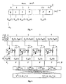
- Fig. 1 shows a known method for suppressing the sidelobe jammer.
- the signal received by the radar antenna is known to be in the time domain.
- the sum S, difference D and auxiliary channel G is supplied to a recursive clutter filter CF, which suppresses the clutter signal.
- CF recursive clutter filter
- SC sidelobe canceller
- the signals of the three channels S, D, G are transformed in a fast Fourier transformation (FFT) from the time domain into the frequency domain.
- FFT fast Fourier transformation
- signal processors with floating-point arithmetic are used to calculate an FFT, allowing a more accurate calculation of the FFT than with fixed-point processors.
- the object of the invention is to provide a method with which one opposite the prior art simpler and faster suppression of the sidelobe jammer is possible.
- the signal received by the radar antenna is first detected in the Sum, difference and auxiliary channel in a Fast Fourier transformation of the time domain transformed into the frequency domain. Subsequently, in the frequency domain the jamming signal, especially the sidelobe jammer, via sidelobe cancellation suppressed.
- the advantage here is that in the frequency domain, the processing of the signals in the sidelobe canceller easier and faster than it is in the time domain according to the prior art is possible.
- Another advantage of the invention Method is that no complicated recursive clutter filters are needed.
- FIG 3 shows, by way of example for the sum channel S n, a frequency spectrum shown in greatly simplified form in an HPRF situation with a clutter-free region M.
- the sum channel S n is shown as a uniqueness range over the sampled Doppler frequency with the pulse repetition frequency PRF.
- the area of the sidelobe clutters and the main club clutter, also referred to as Main Beam Clutter can be seen.
- the advantage here is that after the FFT the signals are in the frequency domain and thus the range of clutter signals without expensive filters, e.g. elliptical Clutter filter can be cut out.
- the radar antenna is known to receive signals in a temporal sequence.
- s k , d k and g k be the signal sequences of samples of the sum, difference and auxiliary channel in the time domain.
- FFT FFT
- N, l and P are a power of 2.
- K s (i) and K d (i) denote the scaling factors for the sum and difference channel of the sub-burst i.
- the coefficients K s and K d are stationary only for a very specific time range. Due to the repeated scanning of the radar antenna, however, the conditions for the coefficients K s and K d change . Thus, the coefficients must be constantly adapted. Such an adaptation may also be required during the FFT.
- the individual sub-bursts i with i 1... 1, where l sub-bursts give a burst, are subject to a temporal sequence (FIG. 4), as already mentioned above, whereas the samples within the sub-bursts are in the frequency domain available.
- the calculation of the scaling factors for the sub-bursts i + 1 with i 1...
- G n * (i) denotes the conjugate complex samples of the corresponding sub-channel G n (i).
- the length P 1 of this initialization phase is advantageously smaller than the length P of the individual sub-bursts i.
- the scaling factors K s (1) and K d (1) are calculated according to the following rule:
- the scaling factors K s (1) and K d (1) are calculated directly after switching on the receiver R x .
- the data of the initialization phase are not needed.
- the scaling factors determined in an initialization phase, l P K s, d (1) used in the first sub-burst l 1 to calculate Y n S (1) and Y n D (1).
- the subsequent method in the second sub-burst essentially corresponds to the method already described in the first sub-burst.
- the individual data Y n S, D (1) to Y n S, D (4) of the sum and difference channel calculated in the four sub-bursts are advantageously combined into a final value Y n S and Y n D for the corresponding burst.
- the individual data of the individual sub-bursts is summarized by means of appropriate twiddle factors [2].
Landscapes
- Engineering & Computer Science (AREA)
- Radar, Positioning & Navigation (AREA)
- Remote Sensing (AREA)
- Computer Networks & Wireless Communication (AREA)
- Physics & Mathematics (AREA)
- General Physics & Mathematics (AREA)
- Radar Systems Or Details Thereof (AREA)
Description
Die Erfindung betrifft ein Verfahren zur Unterdrückung von Jammer-Signalen, im
Empfangssignal von Radarantennen von HPRF-Anwendungen (high pulse repetition
frequency, hohe Pulsrepetitionsfrequenz) gemäß dem Oberbegriff des Patentanspruchs
1.The invention relates to a method for suppression of jammer signals in the received signal from radar antennas of HPRF applications (h igh p r sleeve ePetition f requency, high pulse repetition frequency) according to the preamble of
In der Radartechnik auftretende Störsignale werden in gewollte und ungewollte Störsignale unterschieden. Unter gewollten Störsignalen versteht man das Jammer-Signal. Hierbei kann insbesondere im militärischen Bereich zum Schutz des Ziels vor Ortung und Verfolgung eine gewollte Störung (Jammer-Signal) durch eine elektronische Gegenmaßnahme erwünscht sein. Dazu sendet das Ziel Stör- und Täuschsignale aus, die sich am Radargerät mit den Nutzsignalen überlagern, was zu Fehlinformationen über das Ziel und als Folge davon zu verkehrten Maßnahmen beim Gegner führen soll.In the radar technology occurring interference signals are in wanted and unwanted interference signals distinguished. Under intended interference signals one understands the Jammer signal. This can especially in the military field to protect the goal before Locating and tracking a wanted fault (jammer signal) by an electronic Countermeasure may be desired. For this purpose, the target sends noise and deception signals off, which are superimposed on the radar with the payloads, resulting in misinformation on the objective and, as a consequence, on wrong measures in the To lead opponents.
Unter ungewollten Störsignalen, auch als Clutter-Signale bezeichnet, versteht man im allgemeinen Signale, welche durch Reflexion bzw. Streuung z.B. von auf die Erdoberfläche eingestrahlter Energie entstehen.Under unwanted interference signals, also referred to as clutter signals, is understood in the general signals, which by reflection or scattering e.g. from to the earth's surface radiated energy arise.
Das Jammer-Signal wird hauptsächlich über die Nebenkeulen, im weiteren als Sidelobe bezeichnet, der Radarantenne eingefangen und ist aufgrund der 1/R2-Gesetzmäßigkeit relativ stark. Um dieses, auch als Sidelobe-Jammer bezeichnete Signal zu unterdrücken; wird ein Adaptive Sidelobe Cancellor verwendet [1]. Dieser Adaptive Sidelobe Cancellor basiert auf der Existenz eines Summen-, Differenz- und Hilfskanals der Radarantenne, wobei der Hilfskanal ein isotropes Antennendiagramm, insbesondere 30-40 dB unter dem Maximum der Hauptkeule der Antenne, besitzt.The jammer signal is mainly captured by the side lobes, hereinafter referred to as sidelobe, of the radar antenna and is relatively strong due to the 1 / R 2 law. To suppress this signal, also called sidelobe jammer; An Adaptive Sidelobe Cancellor is used [1]. This Adaptive Sidelobe Cancellor is based on the existence of a sum, difference and auxiliary channel of the radar antenna, wherein the auxiliary channel has an isotropic antenna pattern, in particular 30-40 dB below the maximum of the main lobe of the antenna.
Fig. 1 zeigt ein bekanntes Verfahren zur Unterdrückung des Sidelobe-Jammers. Das
von der Radarantenne empfangene Signal liegt bekanntermaßen im Zeitbereich vor.
In der weiteren Signalverarbeitung wird der Summen- S, Differenz- D und Hilfskanal
G einem rekursiven Clutter-Filter CF zugeführt, welches das Clutter-Signal unterdrückt.
Anschließend wird für die drei Kanäle S, D, G eine Sidelobe Cancellation
mittels eines Sidelobe Cancellers SC durchgeführt. Abschließend wird in dem bekannten
Verfahren die Signale der drei Kanäle S, D, G in einer Fast Fourier Transformation
(FFT) vom Zeitbereich in den Frequenzbereich transformiert.
Zur Berechnung einer FFT werden üblicherweise Signal-Prozessoren mit einer Floating-Point-Arithmetik
verwendet, wodurch eine genauere Berechnung der FFT möglich
ist, als mit Fix-Point-Prozessoren.Fig. 1 shows a known method for suppressing the sidelobe jammer. The signal received by the radar antenna is known to be in the time domain. In the further signal processing, the sum S, difference D and auxiliary channel G is supplied to a recursive clutter filter CF, which suppresses the clutter signal. Subsequently, for the three channels S, D, G, a sidelobe cancellation is performed by means of a sidelobe canceller SC. Finally, in the known method, the signals of the three channels S, D, G are transformed in a fast Fourier transformation (FFT) from the time domain into the frequency domain.
Typically, signal processors with floating-point arithmetic are used to calculate an FFT, allowing a more accurate calculation of the FFT than with fixed-point processors.
Als nachteilig erweist sich allerdings die Verwendung eines aufwendigen rekursiven Clutter-Filters bei anschließender FFT. Außerdem ist dieses Verfahren sehr träge und kann nur langsam auf Änderungen des Sidelobe-Jammers reagieren.However, the use of a complex recursive proves to be disadvantageous Clutter filter with subsequent FFT. In addition, this procedure is very slow and can only react slowly to changes in the Sidelobe Jammer.
Aufgabe der Erfindung ist es, ein Verfahren anzugeben, mit dem eine gegenüber dem Stand der Technik einfachere und schnellere Unterdrückung des Sidelobe-Jammers möglich ist.The object of the invention is to provide a method with which one opposite the prior art simpler and faster suppression of the sidelobe jammer is possible.
Diese Aufgabe wird mit dem Verfahren gemäß Patentanspruch 1 gelöst. Vorteilhafte
Ausführungen der Erfindung sind Gegenstand von Unteransprüchen.This object is achieved by the method according to
Erfindungsgemäß wird das von der Radarantenne empfangene Signal zunächst im Summen-, Differenz- und Hilfskanal in einer Fast Fourier Transformation vom Zeitbereich in den Frequenzbereich transformiert. Anschließend wird im Frequenzbereich das Jammer-Signal, insbesondere das Sidelobe-Jammer, mittels Sidelobe Cancellation unterdrückt.According to the invention, the signal received by the radar antenna is first detected in the Sum, difference and auxiliary channel in a Fast Fourier transformation of the time domain transformed into the frequency domain. Subsequently, in the frequency domain the jamming signal, especially the sidelobe jammer, via sidelobe cancellation suppressed.
Der Vorteil hierbei ist, dass im Frequenzbereich die Verarbeitung der Signale im Sidelobe-Canceller einfacher und schneller erfolgen kann, als es im Zeitbereich gemäß dem Stand der Technik möglich ist. Ein weiterer Vorteil des erfindungsgemäßen Verfahrens ist, dass keine komplizierten rekursiven Clutter-Filter benötigt werden.The advantage here is that in the frequency domain, the processing of the signals in the sidelobe canceller easier and faster than it is in the time domain according to the prior art is possible. Another advantage of the invention Method is that no complicated recursive clutter filters are needed.
Die Erfindung wird im weiteren unter Hinzunahme von Zeichnungen näher erläutert. Es zeigen:
- Fig. 1
- ein Verfahren zur Unterdrückung des Sidelobe-Jammers mittels Sidelobe Cancellation gemäß dem Stand der Technik,
- Fig. 2
- das erfindungsgemäße Verfahren zur Unterdrückung des Sidelobe-Jammers mittels Sidelobe Cancellation, wobei die FFT vor der Sidelobe-Cancellation durchgeführt wird,
- Fig. 3
- beispielhaft für den Summenkanal Sn ein stark vereinfacht dargestelltes Frequenzspektrum in einer HPRF-Situation mit einem clutterfreien Bereich,
- Fig. 4
- einen für die FFT in Sub-Bursts unterteilten Burst mit einer, das erfindungsgemäße Verfahren einleitenden Initialisierungsphase,
- Fig. 5
- eine beispielhafte Darstellung zur Veranschaulichung der Zusammenfassung der einzelnen Sub-Bursts.
- Fig. 1
- a method for suppressing the sidelobe jamming by sidelobe cancellation according to the prior art,
- Fig. 2
- the method according to the invention for suppressing the sidelobe jammer by means of sidelobe cancellation, wherein the FFT is performed before the sidelobe cancellation,
- Fig. 3
- by way of example for the sum channel S n, a frequency spectrum shown in greatly simplified form in an HPRF situation with a clutter-free region,
- Fig. 4
- a burst subdivided into sub-bursts for the FFT with an initialization phase which initiates the method according to the invention,
- Fig. 5
- an exemplary representation to illustrate the summary of the individual sub-bursts.
Fig. 3 zeigt beispielhaft für den Summenkanal Sn ein stark vereinfacht dargestelltes Frequenzspektrum in einer HPRF-Situation mit einem clutterfreien Bereich M. Der Summenkanal Sn ist dabei über die abgetastete Dopplerfrequenz mit der Pulsrepetitionsfrequenz PRF als Eindeutigkeitsbereich dargestellt. Außerdem ist der Bereich des Sidelobe-Clutters und des Hauptkeulenclutters, auch als Main Beam Clutter bezeichnet, zu erkennen.3 shows, by way of example for the sum channel S n, a frequency spectrum shown in greatly simplified form in an HPRF situation with a clutter-free region M. The sum channel S n is shown as a uniqueness range over the sampled Doppler frequency with the pulse repetition frequency PRF. In addition, the area of the sidelobe clutters and the main club clutter, also referred to as Main Beam Clutter, can be seen.
Der Vorteil hierbei ist, dass nach der FFT die Signale im Frequenzbereich vorliegen und somit der Bereich der Clutter-Signale ohne aufwendige Filter, z.B. elliptische Clutter-Filter herausgeschnitten werden kann.The advantage here is that after the FFT the signals are in the frequency domain and thus the range of clutter signals without expensive filters, e.g. elliptical Clutter filter can be cut out.
Die Radarantenne empfängt Signale bekanntlich in einer zeitlichen Abfolge. Somit
seien sk, dk und gk die Signalfolgen von Abtastwerten des Summen-, Differenz- und
Hilfskanals im Zeitbereich. Mittels FFT können diese Signalfolgen aus dem Zeitbereich
in den Frequenzbereich transformiert werden, wobei Sn, Dn und Gn die Abtastwerte
des Summen-, Differenz- und Hilfskanals im Frequenzbereich seien, mit
n=0, 1, 2, 3....N-1. Diese FFT wird auch als N-Punkte-FFT bezeichnet, wobei gilt:
Die FFT wird vorteilhaft in einem sogenannten Burst durchgeführt (Fig. 4). Ein Burst umfaßt dabei N Abtastwerte mit N = 2L und L ∈ |N. Der Burst wird dabei vorteilhaft in ℓ Sub-Bursts unterteilt mit ℓ = 2m und m ∈ {0,1, 2, 3, 4} der Länge P unterteilt. Die Länge P der einzelnen Sub-Bursts berechnet sich aus P:= N/ℓ=2L-m. Dabei sind N, ℓ und P insbesondere eine Potenz von 2.The FFT is advantageously carried out in a so-called burst (FIG. 4). A burst comprises N samples with N = 2 L and L ∈ | N. The burst is advantageously subdivided into ℓ sub-bursts with ℓ = 2 m and m ∈ {0,1, 2, 3, 4} of length P. The length P of the individual sub-bursts is calculated from P: = N / ℓ = 2 Lm . In particular, N, ℓ and P are a power of 2.
Es ist damit möglich, die im Zeitbereich vorliegenden Signalfolgen im Summen-, Differenz- und Hilfskanal in einem einfachen und schnellen FFT-Verfahren in den Frequenzbereich zu transformieren. Dies läßt sich insbesondere dadurch verwirklichen, dass pro Burst insgesamt ℓ FFTs der Länge P durchgeführt werden. Diese Vorgehensweise wird auch als "Decimation in Time FFT" bezeichnet. It is thus possible to use the signal sequences present in the time domain in the sum, difference and and auxiliary channel in a simple and fast FFT method in the frequency domain to transform. This can be achieved in particular by a total of ℓ FFTs of length P are carried out per burst. This approach is also called "Decimation in Time FFT".
Dies bedeutet also, innerhalb der einzelnen Sub-Bursts liegen die Abtastwerte im Frequenzbereich vor. Die Sub-Bursts unterliegen allerdings ihrerseits innerhalb des übergeordneten Bursts einer zeitlichen Abfolge.This means that within the individual sub-bursts the samples are in Frequency range before. The sub-bursts are subject, however, within the higher-level bursts of a time sequence.
In einer vorteilhaften Ausführung der Erfindung erfolgt die Unterdrückung des Sidelobe-Jammers
in den einzelnen Sub-Bursts i mit i=1...ℓ mittels Sidelobe-Cancellation,
wobei in jedem Sub-Burst i folgende Berechnungen durchgeführt werden:
Dabei sind, wie oben bereits beschrieben, Sn(i), Dn(i), Gn(i) die Abtastwerte n = 0, 1, 2, .... N-1 des Summen-, Differenz- und Hilfskanals im Frequenzbereich und i=1...P die Sub-Bursts. Mit Ks(i) und Kd(i) sind die Skalierungsfaktoren für den Summen- und Differenzkanal des Sub-Bursts i bezeichnet.In this case, as already described above, S n (i), D n (i), G n (i) are the sampling values n = 0, 1, 2, .... N-1 of the sum, difference and auxiliary channel in the frequency domain and i = 1 ... P the sub-bursts. K s (i) and K d (i) denote the scaling factors for the sum and difference channel of the sub-burst i.
Die Koeffizienten Ks und Kd sind nur für einen ganz bestimmten Zeitbereich stationär. Aufgrund des wiederholten Scannens der Radarantenne, ändern sich allerdings die Gegebenheiten für die Koeffizienten Ks und Kd. Somit müssen die Koeffizienten ständig angepaßt werden. Eine derartige Anpassung kann auch während der FFT erforderlich sein.The coefficients K s and K d are stationary only for a very specific time range. Due to the repeated scanning of the radar antenna, however, the conditions for the coefficients K s and K d change . Thus, the coefficients must be constantly adapted. Such an adaptation may also be required during the FFT.
Die einzelnen Sub-Bursts i mit i=1...ℓ, wobei ℓ Sub-Bursts einen Burst ergeben, unterliegen,
wie bereits oben erwähnt, einer zeitlichen Abfolge (Fig. 4), wohingegen die
Abtastwerte innerhalb der Sub-Bursts im Frequenzbereich vorliegen. Die Skalierungsfaktoren
Ks(i+1) und Kd(i+1) werden vorteilhaft in einem Sub-Burst i mit i=1...ℓ-1
bestimmt und für die Unterdrückung des Sidelobe-Jammers im zeitlich direkt darauffolgenden
Sub-Burst i+1 mit i=1...ℓ-1 angewendet (Fig. 5). Die Berechnung der Skalierungsfaktoren
für die Sub-Bursts i+1 mit i=1...ℓ-1 erfolgt vorteilhaft gemäß folgender
Vorschrift:


M bezeichnet dabei die Menge der Doppler-Bins, die nicht mit Clutter belegt sind.
Gn *(i) bezeichnet die konjugiert komplexen Abtastwerte des entsprechenden Hilfskanals
Gn(i).The individual sub-bursts i with i = 1... 1, where ℓ sub-bursts give a burst, are subject to a temporal sequence (FIG. 4), as already mentioned above, whereas the samples within the sub-bursts are in the frequency domain available. The scaling factors K s (i + 1) and K d (i + 1) are advantageously determined in a sub-burst i with i = 1... 1-1 and for the suppression of the sidelobe jammer in the directly following sub-burst i. Burst i + 1 with i = 1 ... l-1 applied (Figure 5). The calculation of the scaling factors for the sub-bursts i + 1 with i = 1... 1-1 advantageously takes place according to the following rule:
M refers to the amount of Doppler bins that are not occupied with clutter.
G n * (i) denotes the conjugate complex samples of the corresponding sub-channel G n (i).
Zur Bestimmung der Skalierungsfaktoren Ks(1) und Kd(1), welche zur Unterdrückung
des Sidelobe-Jammers im ersten Sub-Burst i=1 verwendet werden, wird vorteilhaft
eine Initialisierungsphase durchgeführt. Die Länge Pl dieser Initialisierungsphase ist
vorteilhaft kleiner als die Länge P der einzelnen Sub-Bursts i. Vorteilhaft berechnen
sich die Skalierungsfaktoren Ks(1) und Kd(1) gemäß folgender Vorschrift:


Bevorzugt werden die Skalierungsfaktoren Ks(1) und Kd(1) direkt nach Einschalten des Empfängers Rx berechnet. In der weiteren Signalverarbeitung werden die Daten der Initialisierungsphase nicht benötigt.Preferably, the scaling factors K s (1) and K d (1) are calculated directly after switching on the receiver R x . In the further signal processing, the data of the initialization phase are not needed.
Fig. 5 zeigt beispielhaft für einen in 4 Sub-Bursts unterteilten Burst, also ℓ=4, den
Ablauf eines sogenannten adaptiven Processings. Die in einer Initialisierungsphase
Pl ermittelten Skalierungsfaktoren Ks,d(1) werden im ersten Sub-Burst ℓ=1 zur Berechnung
von Yn S(1) und Yn D(1) verwendet. Die Berechnung von Yn S(1) und Yn D(1) für
den Summen- und Differenzkanal erfolgt wie oben bereits beschrieben gemäß folgender
Vorschrift:
Anschließend erfolgt im ersten Sub-Burst die Bestimmung der Skalierungsfaktoren Ks,d(2), also die Skalierungsfaktoren für den zeitlich direkt darauffolgenden zweiten Sub-Burst mit ℓ=2. Das sich darin anschließende Verfahren im zweiten Sub-Burst entspricht im wesentlichen dem bereits beschriebenen Verfahren im ersten Sub-Burst.Subsequently, in the first sub-burst, the determination of the scaling factors K s, d (2), ie the scaling factors for the temporally directly following second sub-burst with ℓ = 2, takes place. The subsequent method in the second sub-burst essentially corresponds to the method already described in the first sub-burst.
Die in den vier Sub-Bursts berechneten Einzeldaten Yn S,D(1) bis Yn S,D(4) des Summen- und Differenzkanals werden vorteilhaft zu einem Endwert Yn S und Yn D für den entsprechenden Burst zusammengefaßt. Die Zusammenfassung der Einzeldaten der einzelnen Sub-Bursts erfolgt mittels entsprechender Twiddle-Faktoren [2]. The individual data Y n S, D (1) to Y n S, D (4) of the sum and difference channel calculated in the four sub-bursts are advantageously combined into a final value Y n S and Y n D for the corresponding burst. The individual data of the individual sub-bursts is summarized by means of appropriate twiddle factors [2].
Claims (7)
- Method for suppression of jammer signals in the received signal from radar antennas in HPRF applications, in particular pulse-Doppler radar systems, by means of Fast Fourier Transformation (FFT) and sidelobe cancellation, with the radar antenna having a sum (S), difference (D) and auxiliary channel (G), characterized in that the received signal is first of all transformed from the time domain to the frequency domain in a Fast Fourier Transformation (FFT) in the sum (S), difference (D) and auxiliary channel (G), and the jammer signal, in particular the sidelobe jammer, is then suppressed by means of sidelobe cancellation (SC) in the frequency domain.
- Method according to Claim 1, characterized in that, after the FFT, the frequency range ±2Vr/λ; where Vr is the speed of the HPRF application and λ is the wavelength of the received signal, is cut out of the frequency spectrum of the received signal in order to eliminate clutter signals.
- Method according to one of the preceding claims, characterized in that the Fast Fourier Transformation is carried out in a burst comprising N sample values where N=2L and LE|N, with the burst being subdivided into ℓ sub-bursts where ℓ=2m and mE{0,1,2,3,4} of length P.
- Method according to Claim 3, characterized in that, in order to suppress the sidelobe jammer by means of sidelobe cancellation in the individual sub-bursts i
where i=1...ℓ, the calculation
Yn s (i)=Sn(i)-Ks(i)*Gn(i) is carried out for the sum channel (S), and
Yn D (i)=Dn(i)-Kd(i)*Gn(i) is carried out for the difference channel (D),
where
Sn(i),Dn(i),Gn(i): sample values of the sum (S), difference (D) and auxiliary channel (G) in the frequency domain of the sub-burst i,
n=0,1,2,...N-1,
Ks(i),Kd(i): scaling factors for the sub-burst i+1. - Method according to Claim 4, characterized in that the corresponding scaling factors Ks(i) and Kd(i) are determined in a sub-burst i where i=1...ℓ-1, with the calculated scaling factors being used for the elimination of the sidelobe jammer in the directly successive sub-burst i+1 where i=1...ℓ-1 and with the calculation of the scaling factors for the sub-bursts i where i=1...ℓ-1 being carried out as follows:and
 where i = 1,...,ℓ-1,
M: clutter-free signal range - Method according to Claim 5, characterized in that an initialization phase is carried out in order to determine the scaling factors Ks(1) and Kd(1) for the sub-burst i=1, the length Pi of which initialization phase is shorter than P, and with the scaling factors Ks(1) and Kd(1) being calculated as follows in the initialization phase:


- Method according to one of the preceding claims, characterized in that the individual data items Yn S (i) and Yn D (i), which are calculated in the individual sub-bursts i, for the sum (S) and difference channel (D) are combined to form a final value Yn S and Yn D for the sum (S) and difference channel (D) for the corresponding burst.
Applications Claiming Priority (2)
| Application Number | Priority Date | Filing Date | Title |
|---|---|---|---|
| DE10140498A DE10140498C1 (en) | 2001-08-17 | 2001-08-17 | Method for the suppression of jammer signals |
| DE10140498 | 2001-08-17 |
Publications (3)
| Publication Number | Publication Date |
|---|---|
| EP1286415A2 EP1286415A2 (en) | 2003-02-26 |
| EP1286415A3 EP1286415A3 (en) | 2004-01-07 |
| EP1286415B1 true EP1286415B1 (en) | 2005-08-10 |
Family
ID=7695828
Family Applications (1)
| Application Number | Title | Priority Date | Filing Date |
|---|---|---|---|
| EP02014487A Expired - Lifetime EP1286415B1 (en) | 2001-08-17 | 2002-06-29 | Method for suppressing jammer signals |
Country Status (3)
| Country | Link |
|---|---|
| US (1) | US6731233B2 (en) |
| EP (1) | EP1286415B1 (en) |
| DE (2) | DE10140498C1 (en) |
Families Citing this family (9)
| Publication number | Priority date | Publication date | Assignee | Title |
|---|---|---|---|---|
| US7876256B2 (en) * | 2004-11-26 | 2011-01-25 | Saab Ab | Antenna back-lobe rejection |
| US7492329B2 (en) | 2006-10-12 | 2009-02-17 | Hewlett-Packard Development Company, L.P. | Composite material with chirped resonant cells |
| US9674781B2 (en) | 2014-09-05 | 2017-06-06 | Google Inc. | Systems and methods for waking up devices of a fabric network |
| US9801129B2 (en) * | 2014-09-05 | 2017-10-24 | Google Inc. | Systems and methods for disseminating messages among a fabric network |
| CN109655795B (en) * | 2019-01-24 | 2020-06-30 | 南京莱斯电子设备有限公司 | Meter-wave radar co-frequency narrow pulse interference suppression method and system based on waveform entropy |
| CN111105509B (en) * | 2019-12-26 | 2022-03-08 | 成都纳雷科技有限公司 | ETC vehicle detection method and system based on millimeter wave radar and storage medium |
| CN111948614B (en) * | 2020-08-20 | 2023-01-10 | 电子科技大学 | Phased array radar broadband self-interference radio frequency domain sectional cancellation system and method |
| CN114428228B (en) * | 2022-01-24 | 2024-06-07 | 西安电子科技大学 | Clutter suppression method for high-repetition-frequency sum-difference antenna radar seeker |
| CN117784026B (en) * | 2024-02-26 | 2024-05-03 | 中国人民解放军空军预警学院 | Space-time-frequency domain combined active anti-composite interference method and device |
Family Cites Families (6)
| Publication number | Priority date | Publication date | Assignee | Title |
|---|---|---|---|---|
| US6268821B1 (en) * | 1977-10-21 | 2001-07-31 | Raytheon Company | Multiple band sidelobe canceller |
| US4246585A (en) * | 1979-09-07 | 1981-01-20 | The United States Of America As Represented By The Secretary Of The Air Force | Subarray pattern control and null steering for subarray antenna systems |
| US5245347A (en) * | 1980-12-29 | 1993-09-14 | Raytheon Company | All weather tactical strike system (AWTSS) and method of operation |
| FR2527785A1 (en) * | 1982-05-27 | 1983-12-02 | Thomson Csf | METHOD AND DEVICE FOR REDUCING THE POWER OF THE INTERFERENCE SIGNALS RECEIVED BY THE LATERAL LOBES OF A RADAR ANTENNA |
| US4720712A (en) * | 1985-08-12 | 1988-01-19 | Raytheon Company | Adaptive beam forming apparatus |
| US5841395A (en) * | 1997-09-12 | 1998-11-24 | Raytheon Corporation | Localized interference nulling preprocessor |
-
2001
- 2001-08-17 DE DE10140498A patent/DE10140498C1/en not_active Withdrawn - After Issue
-
2002
- 2002-06-29 EP EP02014487A patent/EP1286415B1/en not_active Expired - Lifetime
- 2002-06-29 DE DE50203864T patent/DE50203864D1/en not_active Expired - Lifetime
- 2002-08-16 US US10/219,813 patent/US6731233B2/en not_active Expired - Fee Related
Also Published As
| Publication number | Publication date |
|---|---|
| US6731233B2 (en) | 2004-05-04 |
| DE50203864D1 (en) | 2005-09-15 |
| DE10140498C1 (en) | 2003-05-15 |
| EP1286415A2 (en) | 2003-02-26 |
| US20040051658A1 (en) | 2004-03-18 |
| EP1286415A3 (en) | 2004-01-07 |
Similar Documents
| Publication | Publication Date | Title |
|---|---|---|
| DE102018132745B4 (en) | FMCW RADAR WITH INTERFERENCE REJECTION IN THE TIME DOMAIN | |
| DE69713837T2 (en) | ADAPTIVE FILTERING OF SIGNAL-ADJUSTED DATA | |
| US5539412A (en) | Radar system with adaptive clutter suppression | |
| DE102019106529A1 (en) | FMCW RADAR WITH INTERFERENCE SUPPRESSION USING AN ARTIFICIAL NEURAL NETWORK | |
| DE102005063417B4 (en) | Antenna for a high resolution synthetic aperture radar device | |
| DE60309006T2 (en) | NOISE REDUCTION DEVICE AND METHOD FOR PHASE-CONTROLLED SYSTEMS | |
| DE68924846T2 (en) | RADAR WITH ADJUSTABLE WAVE SHAPE. | |
| EP0795762B1 (en) | Method for azimuth scaling for SAR-data and high precision processor for two-dimensional processing of scan-SAR data | |
| DE69214257T2 (en) | Improved ISAR imaging radar system | |
| DE3787015T2 (en) | IMPULSE RADIATION RADAR DEVICE IN THE FREQUENCY RANGE FOR ELIMINATION OF INTERFERENCE. | |
| DE69906305T2 (en) | HIGH GAIN NON-COHERENT SIGNAL PROCESSING FOR IMPROVED DETECTION ESTIMATION | |
| EP1296157B1 (en) | Method for calibrating radar signals from the sub-apertures of the antenna of a two-channel SAR/MTI radar system | |
| EP0533220A1 (en) | Target distinction method, especially for HPRF Doppler radar | |
| DE19615353C2 (en) | Method for the cost-effective determination of an impulse response of a high-resolution band-limited radar channel | |
| EP1286415B1 (en) | Method for suppressing jammer signals | |
| DE69120169T2 (en) | Acceleration compensation using an adaptive filter | |
| EP4196818B1 (en) | Method and device for determining frequency disturbances in a received signal of an active multi-channel sar system | |
| DE3120490A1 (en) | METHOD AND DEVICE FOR REAL-TIME RADAR SIGNAL PROCESSING | |
| DE69110646T2 (en) | Digitally encoded pulse signal processing. | |
| EP0487940B1 (en) | Pulse doppler radar | |
| DE3301625C1 (en) | Method and device for reducing the power of interfering signals received from the side lobes of the antenna of a frequency agile radar device | |
| DE3835343A1 (en) | METHOD AND DEVICE FOR COMPENSATING THE INTERFERENCE SPEED IN A COHERENT DOPPLER RADAR WITH VARIABLE AMBIENT SPEED | |
| DE3909874C2 (en) | Method for digitizing and signal processing of received signals of a phased array receiving system and device for carrying out the method | |
| DE4117849C2 (en) | Method for generating a reference function for pulse compression of frequency, phase and / or amplitude modulated signals | |
| EP0789252B1 (en) | Method of suppression of inteference signals in a puls doppler radar |
Legal Events
| Date | Code | Title | Description |
|---|---|---|---|
| PUAI | Public reference made under article 153(3) epc to a published international application that has entered the european phase |
Free format text: ORIGINAL CODE: 0009012 |
|
| AK | Designated contracting states |
Kind code of ref document: A2 Designated state(s): AT BE CH CY DE DK ES FI FR GB GR IE IT LI LU MC NL PT SE TR |
|
| AX | Request for extension of the european patent |
Extension state: AL LT LV MK RO SI |
|
| PUAL | Search report despatched |
Free format text: ORIGINAL CODE: 0009013 |
|
| AK | Designated contracting states |
Kind code of ref document: A3 Designated state(s): AT BE CH CY DE DK ES FI FR GB GR IE IT LI LU MC NL PT SE TR |
|
| AX | Request for extension of the european patent |
Extension state: AL LT LV MK RO SI |
|
| RIC1 | Information provided on ipc code assigned before grant |
Ipc: 7G 01S 7/285 A Ipc: 7H 01Q 3/26 B |
|
| 17P | Request for examination filed |
Effective date: 20040506 |
|
| AKX | Designation fees paid |
Designated state(s): DE FR GB SE |
|
| GRAP | Despatch of communication of intention to grant a patent |
Free format text: ORIGINAL CODE: EPIDOSNIGR1 |
|
| GRAS | Grant fee paid |
Free format text: ORIGINAL CODE: EPIDOSNIGR3 |
|
| GRAA | (expected) grant |
Free format text: ORIGINAL CODE: 0009210 |
|
| AK | Designated contracting states |
Kind code of ref document: B1 Designated state(s): DE FR GB SE |
|
| REG | Reference to a national code |
Ref country code: GB Ref legal event code: FG4D Free format text: NOT ENGLISH |
|
| REF | Corresponds to: |
Ref document number: 50203864 Country of ref document: DE Date of ref document: 20050915 Kind code of ref document: P |
|
| GBT | Gb: translation of ep patent filed (gb section 77(6)(a)/1977) |
Effective date: 20050917 |
|
| REG | Reference to a national code |
Ref country code: SE Ref legal event code: TRGR |
|
| ET | Fr: translation filed | ||
| PLBE | No opposition filed within time limit |
Free format text: ORIGINAL CODE: 0009261 |
|
| STAA | Information on the status of an ep patent application or granted ep patent |
Free format text: STATUS: NO OPPOSITION FILED WITHIN TIME LIMIT |
|
| 26N | No opposition filed |
Effective date: 20060511 |
|
| PGFP | Annual fee paid to national office [announced via postgrant information from national office to epo] |
Ref country code: SE Payment date: 20130619 Year of fee payment: 12 Ref country code: GB Payment date: 20130619 Year of fee payment: 12 Ref country code: DE Payment date: 20130620 Year of fee payment: 12 |
|
| PGFP | Annual fee paid to national office [announced via postgrant information from national office to epo] |
Ref country code: FR Payment date: 20130703 Year of fee payment: 12 |
|
| REG | Reference to a national code |
Ref country code: DE Ref legal event code: R119 Ref document number: 50203864 Country of ref document: DE |
|
| PG25 | Lapsed in a contracting state [announced via postgrant information from national office to epo] |
Ref country code: SE Free format text: LAPSE BECAUSE OF NON-PAYMENT OF DUE FEES Effective date: 20140630 |
|
| REG | Reference to a national code |
Ref country code: SE Ref legal event code: EUG |
|
| GBPC | Gb: european patent ceased through non-payment of renewal fee |
Effective date: 20140629 |
|
| REG | Reference to a national code |
Ref country code: DE Ref legal event code: R119 Ref document number: 50203864 Country of ref document: DE Effective date: 20150101 |
|
| REG | Reference to a national code |
Ref country code: FR Ref legal event code: ST Effective date: 20150227 |
|
| PG25 | Lapsed in a contracting state [announced via postgrant information from national office to epo] |
Ref country code: DE Free format text: LAPSE BECAUSE OF NON-PAYMENT OF DUE FEES Effective date: 20150101 |
|
| PG25 | Lapsed in a contracting state [announced via postgrant information from national office to epo] |
Ref country code: GB Free format text: LAPSE BECAUSE OF NON-PAYMENT OF DUE FEES Effective date: 20140629 Ref country code: FR Free format text: LAPSE BECAUSE OF NON-PAYMENT OF DUE FEES Effective date: 20140630 |