EP1295845B1 - Sicherheitsvorrichtung für Kegarmatur - Google Patents
Sicherheitsvorrichtung für Kegarmatur Download PDFInfo
- Publication number
- EP1295845B1 EP1295845B1 EP02020598A EP02020598A EP1295845B1 EP 1295845 B1 EP1295845 B1 EP 1295845B1 EP 02020598 A EP02020598 A EP 02020598A EP 02020598 A EP02020598 A EP 02020598A EP 1295845 B1 EP1295845 B1 EP 1295845B1
- Authority
- EP
- European Patent Office
- Prior art keywords
- housing
- down pipe
- locking member
- safety device
- valve
- Prior art date
- Legal status (The legal status is an assumption and is not a legal conclusion. Google has not performed a legal analysis and makes no representation as to the accuracy of the status listed.)
- Expired - Lifetime
Links
- 235000013405 beer Nutrition 0.000 title claims abstract description 29
- 238000005452 bending Methods 0.000 claims abstract description 39
- 239000007788 liquid Substances 0.000 claims abstract description 11
- 229920001971 elastomer Polymers 0.000 claims description 9
- 239000000806 elastomer Substances 0.000 claims description 9
- 230000002093 peripheral effect Effects 0.000 claims 1
- CURLTUGMZLYLDI-UHFFFAOYSA-N Carbon dioxide Chemical compound O=C=O CURLTUGMZLYLDI-UHFFFAOYSA-N 0.000 description 6
- 230000006378 damage Effects 0.000 description 4
- 208000027418 Wounds and injury Diseases 0.000 description 3
- 229910002092 carbon dioxide Inorganic materials 0.000 description 3
- 239000001569 carbon dioxide Substances 0.000 description 3
- 208000014674 injury Diseases 0.000 description 3
- 235000013361 beverage Nutrition 0.000 description 2
- 230000035622 drinking Effects 0.000 description 2
- 238000000034 method Methods 0.000 description 2
- 241000238631 Hexapoda Species 0.000 description 1
- 230000004308 accommodation Effects 0.000 description 1
- 230000015572 biosynthetic process Effects 0.000 description 1
- 238000004140 cleaning Methods 0.000 description 1
- 230000008878 coupling Effects 0.000 description 1
- 238000010168 coupling process Methods 0.000 description 1
- 238000005859 coupling reaction Methods 0.000 description 1
- 230000009977 dual effect Effects 0.000 description 1
- 239000011521 glass Substances 0.000 description 1
- 238000009434 installation Methods 0.000 description 1
- 230000001788 irregular Effects 0.000 description 1
- 230000002265 prevention Effects 0.000 description 1
- 238000004064 recycling Methods 0.000 description 1
Images


Classifications
-
- B—PERFORMING OPERATIONS; TRANSPORTING
- B67—OPENING, CLOSING OR CLEANING BOTTLES, JARS OR SIMILAR CONTAINERS; LIQUID HANDLING
- B67D—DISPENSING, DELIVERING OR TRANSFERRING LIQUIDS, NOT OTHERWISE PROVIDED FOR
- B67D1/00—Apparatus or devices for dispensing beverages on draught
- B67D1/08—Details
- B67D1/0829—Keg connection means
- B67D1/0831—Keg connection means combined with valves
- B67D1/0838—Keg connection means combined with valves comprising means for preventing blow-out on disassembly of the spear valve
-
- Y—GENERAL TAGGING OF NEW TECHNOLOGICAL DEVELOPMENTS; GENERAL TAGGING OF CROSS-SECTIONAL TECHNOLOGIES SPANNING OVER SEVERAL SECTIONS OF THE IPC; TECHNICAL SUBJECTS COVERED BY FORMER USPC CROSS-REFERENCE ART COLLECTIONS [XRACs] AND DIGESTS
- Y10—TECHNICAL SUBJECTS COVERED BY FORMER USPC
- Y10T—TECHNICAL SUBJECTS COVERED BY FORMER US CLASSIFICATION
- Y10T137/00—Fluid handling
- Y10T137/2931—Diverse fluid containing pressure systems
- Y10T137/3115—Gas pressure storage over or displacement of liquid
- Y10T137/3127—With gas maintenance or application
- Y10T137/314—Unitary mounting for gas pressure inlet and liquid outlet
-
- Y—GENERAL TAGGING OF NEW TECHNOLOGICAL DEVELOPMENTS; GENERAL TAGGING OF CROSS-SECTIONAL TECHNOLOGIES SPANNING OVER SEVERAL SECTIONS OF THE IPC; TECHNICAL SUBJECTS COVERED BY FORMER USPC CROSS-REFERENCE ART COLLECTIONS [XRACs] AND DIGESTS
- Y10—TECHNICAL SUBJECTS COVERED BY FORMER USPC
- Y10T—TECHNICAL SUBJECTS COVERED BY FORMER US CLASSIFICATION
- Y10T137/00—Fluid handling
- Y10T137/598—With repair, tapping, assembly, or disassembly means
- Y10T137/612—Tapping a pipe, keg, or apertured tank under pressure
- Y10T137/613—With valved closure or bung
- Y10T137/6137—Longitudinal movement of valve
Definitions
- This invention relates to a double valve arrangement used for a pressurized beer keg, said arrangement comprises a safety device in order to prevent a valve body popped out of the keg under pressure causing unintended personal injury, or when the dismount is handled by somebody who is unauthorized to do so.
- kegs are commonly used.
- the keg is highly pressurized with carbon dioxide gas inside.
- carbon dioxide gas When serving beer out of the keg into a drinking glass, more carbon dioxide gas is pressed into the keg through a gas valve, making it possible to dispense the beer out through a liquid valve.
- a double valve arrangement installed in the insect part of the keg, serves dual purposes, one for gas passage, and the other for liquid passage.
- the keg is empty, it is returned to a beverage manufacturer for recycling and refill. The keg has to be cleaned prior to the procedure of refilling it with beer.
- valve body when being dismounted from the keg, could pop out suddenly due to the possible gas pressure that remains within the container, causing serious personal injury to the one who bends working on it.
- keg is handled by somebody who is either unauthorized to do so, or unaware of the potential danger, same serious result could also ensure.
- a valve body is formed with a projection having radical extent and axial location that the valve body can be moved down through the keg neck ring when separate from the valve housing. But the valve housing and the valve body can be coupled together only after the valve body with its projection has been moved down through the neck ring. Since the device cannot be inserted into the keg dispensing aperture in a fully assembled condition, it is often considered inconvenient and time-consuming for operation and handling.
- a recent US patent (5,833,098) has been proposed with an idea of a stopper to prevent the popping out of the spear tube by hooking the stopper portion to the keg neck interface. But it is only possible to completely detach the spear tube from the beer keg with the aid of both a tool and a jig, in that the tool is rotated on the axial center of the spear tube and the jig is employed to pull the stopper portion into an inside of the body before a complete detachment can possibly be achieved.
- the safety device under the present invention as defined by claim 1, can be inserted into the beer keg dispensing aperture as a wholly assembled piece by being pushed down into it axially and screwed tight, and it can be pulled out as a whole piece by a special tap.
- a double valve body is formed with a locking member disposed between a down pipe and a housing. Extended from the locking member there are two bendings in opposite directions, one of which inwardly in contact with the down pipe, and the other outwardly secured to the housing.
- the flaps of the locking member normally protrude out to prevent the detachment of the valve body out of the beer keg neck ring.
- the down pipe moves downward, and the direction of the inward bending of the locking member changes accordingly, along from a lower portion of the down pipe to an enlarged portion of the down pipe, which results in the movement of the locking member, retrieving the flaps to the inside of the housing in order that the valve body could be moved out without any difficulty.
- the special tap is only available to the authorized personnel at the manufacturers.
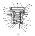
- a double valve body 1 is disposed in a neck ring 3 of a beer keg 2.
- This double valve body 1 comprises a housing 1c and a down pipe 8, both arranged in a way by an external coil spring 9 and a base disc 10. The details shall be provided below.
- the housing 1c is formed in a cylindrical shape.
- the top portion of the housing 1c is disposed in the neck ring 3 of the keg 2.
- ratchets 1a Inside the top portion of the housing 1c there are two ratchets 1a formed toward the center axis, with equal and predetermined intervals between them. These two ratchets 1a are to serve the purpose of engaging a dispense head for liquid, or the special tap (not shown) for installation and dismantlement.
- the inside cylindrical shape abruptly becomes smaller, forming an inside shoulder portion 1e. Below this inside shoulder portion 1e, the inside cylindrical shape again becomes abruptly smaller, forming an inside collar 1f which defines the extent of the housing 1c opening.
- the down pipe 8 which is installed within the housing 1c, is a long tube, extending down to the bottom of the keg 2.
- the top of the down pipe 8 is formed in a flange portion 18.
- the flange portion 18 is such that the down pipe 8 can pass through the housing 1c by the insider collar 1f.
- valve ring 4 As shown in FIG. 2A through FIG. 2E, within the upper portion 16 of the down pipe 8, there is an internal coil spring 7, which sits on the shoulder portion 17 of the down pipe 8. Between the flange portion 18 of the down pipe 8 and the underside of the inside collar 1f of the housing 1c, there is a valve ring 4 and a valve plug 6. The valve ring 4, except its surface, is wrapped with elastomer 5. The valve ring 4 with the elastomer 5 as one piece is larger in diameter than the opening of the housing 1c, as defined by the inside collar 1f. This design enables the valve ring 4 to be positioned, supported by the valve plug 6, directly under the inside collar 1f of the housing 1c.
- the valve plug 6 is a piece of round shape, with its surface smaller than the bottom. It is formed with five square pieces 6a, all of the same size and dimension under its bottom for support and stability, with equal and predetermined intervals between these square pieces 6a. For support, the valve plug 6 itself is pushed upward by the top of the internal coil spring 7.
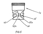
- windows 1d formed in circumferential direction.
- two predetermined, rectangular openings 25 formed in a vertical way. These two openings 25 are narrow and parallel to each other. The low ends of the openings 25 are formed in grooves 25a.
- a predetermined incision 26 positioned in the center below the two openings 25.
- FIG. 1 and FIG. 3 there is a base disc 10 in the housing 1c to support the external coil spring 9.
- the base disc 10 is in a ring shape, the inside circular size of which allows the passage of the down pipe 8, except the flange portion 18 at the top.
- the base disc 10 is in a ring shape, the inside circular size of which allows the passage of the down pipe 8, except the flange portion 18 at the top.
- the base disc 10 is in a ring shape, the inside circular size of which allows the passage of the down pipe 8, except the flange portion 18 at the top.
- the base disc 10 is in a ring shape, the inside circular size of which allows the passage of the down pipe 8, except the flange portion 18 at the top.
- the base disc 10 is in a ring shape, the inside circular size of which allows the passage of the down pipe 8, except the flange portion 18 at the top.
- the base disc 10 is in a ring shape, the inside circular size of which allows the passage of the down pipe 8, except the flange
- flanges 10a formed between the recesses 10b and 10c. These flanges 10a form an irregular outside circular shape of the base disc 10 in that the two recesses 10b and the extended recess 10c are different in size. As a result, there are unequal intervals between these three recesses.
- the outside circular shape of the base disc 10 is formed such that it is possible to place the base disc 10 in the housing 1c.
- FIG. 1 there is a locking member 12 disposed between the external coil spring 9 and the inside wall of the housing 1c.
- the main part of the locking member 12 is a body piece 24.
- On each side of the body piece 24 is a flap 20.
- the body piece 24 and the two flaps 20 are formed in a 90 degree shape.
- the low end portion of each flap 20 is formed in a hook 21 so that there is a hook 21 on each side of the body piece 24.
- the upper portion of the flaps 20 is bigger than the lower portion of the flaps 20.
- the distance between the top and bottom of the flaps 20 enables the flaps 20 to be readily inserted into the two openings 25 of the housing 1c outwardly.
- the hooks 21 are secured into the grooves 25a at the bottom of the openings 25.
- the hooks 21 are positioned in this way, the upper portions of the flaps 20 are in a free position as the flaps 20 can protrude out of the housing 1c to serve a locking purpose, or they can also be retrieved inside the wall of the housing 1c, depending upon the different positions of the body piece 24 of the locking member 12.
- Another bending 14 is formed in the middle of the projection 22.
- This bending 14 extends outwardly and is smaller in size than the inward bending 13 in that the projection 22 is larger than the outward bending 14.
- the direction of the outward bending 14 is opposite to that of the inward bending 13, but is the same as that of the flaps 20.
- the formation of the outward bending 14 leaves an opening cut 23 in the projection 22.
- This opening cut 23 in the projection 22 is the same in size as the outward bending 14, and does not extend to the inward bending 13.
- the whole locking member 12 is formed from one piece.
- the locking member 12 can also be formed from two pieces.
- the outward bending 14 is formed in a way that when two hooks 21 are secured in the grooves 25a of the openings 25 of the housing 1c, the tip of the outward bending 14 is settled in the area left by the incision 26 of the housing 1c.
- valve for liquid passage is formed between the valve plug 6 and the valve ring 4 with elastomer 5.
- This liquid valve is closed in that the internal coil spring 7 disposed in the upper portion 16 of the down pipe 8 always pushes upward against the valve plug 6.
- the valve plug 6 With the support of five square pieces 6a, the valve plug 6 is secured between the internal coil spring 7 and the valve ring 4 wrapped with the elastomer 5.
- the second valve designed for gas passage is formed between the inside collar 1f of the housing 1c and the valve ring 4 wrapped with the elastomer 5.
- the external coil spring 9 disposed between the down pipe 8 and the housing 1c pushes upward under the flange portion 18 of the down pipe 8.
- the gas valve is closed under the force of the external coil spring 9 unless the valve ring 4 is pushed down by a force outside, like a dispense head or a tap.
- the inside circular shape of the base disc 10 allows the down pipe 8, both the upper portion 16 and the lower portion 15, to pass through until the flange portion 18.
- To properly assemble the down pipe 8 and the base disc 10 in the housing 1c place the lower portion 15 of the down pipe 8 through the base disc 10 with the upper portion 16 of the down pipe 8 in the housing 1c.
- the base disc 10 When the base disc 10 is installed, it can only come into the housing 1c when the three recesses 10b and 10c aim at the bayonet pieces 11 of the housing 1c, as the recesses 10b and 10c give room for the bayonet pieces 11.
- the base disc 10 After the base disc 10 comes past the bayonet pieces 11, it is both possible and necessary to rotate the base disc 10 to the right so that the bayonet pieces 11 are properly placed in the grooves 10d of the base disc 10, with the extended recess 10c positioned where the incision 26 and the two openings 25 of the housing 1c are located.
- the base disc 10 disposed in this way supports the external coil spring 9 from below.
- the external coil spring 9 pushes upward under the flange portion 18 of the down pipe 8.
- both the liquid valve and the gas valve are closed in that the internal coil spring 7 pushes upward against the valve plug 6 which is in contact with the valve ring 4, and the external coil spring 9 pushes under the flange portion 18 of the down pipe 8 and the top of the flange portion 18 is in contact with the valve ring 4 wrapped with the elastomer 5.
- the end of the inward bending 13 of the locking member 12 is in contact with the lower portion 15 of the down pipe 8.
- the locking member 12 is disposed between the external coil spring 9 and the inside wall of the housing 1c, with the hooks 21 secured in the grooves 25a of the opening 25 and the tip of the outward bending 14 settled in the position of the incision 26.
- the upper part of the flaps 20 protrudes outside the wall of the housing 1c, serving to prevent the valve body from being pulled upward out of the neck ring 3 of the keg 2 by a person not authorized to do so, as the protruding part of the flaps 20 works against the under surface of the beer keg 2.
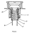
- valve body 1 in the fully assembled state could only be pulled upward out of the neck ring 3 of the keg 2 by an authorized person with the aid of the special tap.
- the tap is first inserted into the top portion of the double valve body 1 above the inside collar 1f and is engaged to the ratchets 1a by operation of rotation.
- the valve ring 4 is also pushed down, creating a clearance for gas passage 28 between the valve ring 4 wrapped with the elastomer part 5 and the inside collar 1f of the housing 1c.
- the remains of the gas in the beer keg 2 is reduced and finally released.
- the double valve body 1 can not be completely detached away from the keg 2 due to the work of the locking member 12 with the upper portion of the flaps 20 protruding out of the housing 1c unless the tap is further pushed down.
- the down pipe 8 against force of the external coil spring 9, is pushed down accordingly.
- the contact position of the lower portion 15 with the end of the inward bending 13 of the locking member 12 changes to a new position of the upper portion 16.
- the safety device of the invention provides a highly reliable, yet simplified means to protect the double valve body 1 from any unauthorized persons, causing unintended injury or damage.
- the projection 22 of the locking member 12 can be extended in accordance with the changed position of the shoulder portion 17 of the down pipe 18 to achieve a new result for the safety purpose.
Landscapes
- Devices For Dispensing Beverages (AREA)
- Medicines Containing Material From Animals Or Micro-Organisms (AREA)
Claims (10)
- Eine Sicherheitsvorrichtung für Kegarmatur(2) besteht aus:ein Doppelventil(1), das am Halsring(3) der Kegarmatur(2) montiert wird, d.h. das Doppelventil, das ein zylindrisches Gehäuse(1c) hat,ein unteres Rohr(8), das einen Flanschteil(18) obenauf im Kontakt mit einem Ventilring(4), und einen niederen Teil(15), der sich nach unten durch das Gehäuse ausdehnt,ein Gasventil, das zwischen einem inneren Kragen(1f) des Gehäuses(1c) und des Ventilrings(4) gebildet wird,ein Flüssigkeitsventil, das zwischen dem Ventilring(4) und einem Ventilpfropfen(6), der von inneren Spiralfeder(7) im unteren Rohr(8) getützt wird, gebildet wird,eine äußere Spiralfeder(9), die zwischen dem Gehäuse(1c) und dem unteren Rohr(8) angeordnet wird. Die äußere Spiralfeder stützt die Bodenseite des Flanschteils(18) vom unteren Rohr,eine Scheibe(10), die im Gehäuse angeordnet wird. Die Scheibe stützt die äußere Spiralfeder(9),ein Sperrglied(12), das zwischen dem Gehäuse(1c) und dem unteren Rohr(8) angeordnet wird. Das Sperrglied hat zwei Flügel(20), jeder davon hat einen Haken(21) am unteren Ende. Die Haken(21) werden fest an zwei parallelen Öffnungen(25) verschlossen, die an der Wand des Gehäuses gebildet wird. Das Sperrglied(12) hat einen nach außen gerichteten Biegeteil(14), der am Einschnitt(26) des Gehäuses festgesetzt wird, und einen nach innen gerichteten Biegeteil, der im Kontakt mit dem niederen Teil des unteren Rohres. Das Sperrglied(12) wird so angeordnet wird, dass Flügel(20) aus dem Gehäuse(1c) durch Öffnungen(25) herausgestreckt warden. Hiermit dient das Sperrglied zum sicheren Zweck, um den Knall der Doppelventilanordnung aus Kegarmatur zu verhindern, wenn die Sicherheitsvorrichtung am Halsring der Kegarmatur montiert wird. Es wird so bezeichnet, dass das Sperrglied(12) außerdem einen nach innen gerichteten Biegeteil(13), der im Kontakt mit dem niederen Teil(15) des unteren Rohres steht.
- Das Gehäuse, das von der Sicherheitsvorrichtung der Forderung 1 erwähnt wird, hat Kreisesfenster(ld) an der Wand. Das Gehäuse hat einen äußerlich eingefädelten Spitzenteil(1b), der den Halsring unterbringt, der innerlich eingefädelt wird.
- Die Öffungen(25) an der Wand des Gehäuses(1c), die von der Sicherheitsvorrichtung der Forderung 1 erwähnt werden, sind rechteckig und senkrecht vorherbetimmt. Jede hat eine Rinne(25a) am peripherischen Boden für Haken(21) des Sperrgliedes.
- Der Einschnitt(26), der von der Sicherheitsvorrichtung der Forderung 1 erwähnt wird, wird an der Bodenseite des Gehäuses gebildet. Unten in der Mitte positionierte Öffnungen(25) für den nach außen gerichteten Biegeteil(14) des Sperrgliedes.
- Der Ventilring(4), der von der Sicherheitsvorrichtung der Forderung 1 erwähnt wird, wird mit einem Elastomerenteil(5) verpackt, um den Ventilpfropfen(6) un unterbringen.
- Der Ventilpfropfen(6), der von der Sicherheitsvorrichtung der Forderung 1 erwähnt wird, stützt sich auf fünf gleichen Quadratstücken(6a). Die Quadratstücke stehen im Kontakt mit der inneren Spiralfeder(7), die im unteren Rohr angeordnet wird.
- Das untere Rohr(8), das von der Sicherheitsvorrichtung der Forderung 1 erwähnt wird, nämlich der Flanschteil(18) wie folgendes, hat einen höheren Teil(16), der größer als der niedere Teil(15) im Durchmesser ist. Es gibt einen Schulterteil(17) zwischen dem höheren Teil und dem niederen Teil. Der Schulterteil(17) wird so gebildet, dass die innere Spiralfeder(7) im höheren Teil(16) des unteren Rohres angeordnet wird.
- Das Sperrglied(12), das von der Sicherheitsvorrichtung der Forderung 1 erwähnt wird, hat jeweils ein Stück(24) Flügel(20) an den beiden Seiten. Der Flügel ist ein Vorsprung(22) aus der Mitte, wo der nach außen gerichtete Biegeteil(14) gebildet wird. Eine Öffnung(23) wird am Vorsprung übrigbehalten. Der nach außen gerichtete Biegeteil hat eine Spitze am Ende. Die Spitze wird am Einschnitt(26) des Gehäuses angeordnet. Der nach innen gerichtete Biegeteil(13) wird am Ende des Vorsprungs(22) gebildet. Der nach innen gerichtete Biegeteil hat ein Ende, das im Kontakt mit dem niederen Teil(15) des unteren Rohres steht, wenn sich die Sicherheitsvorrichtung in der vollen Situation befindet. Diese zwei Biegeteile(13, 14) reichen in gegenüberstehender Richtung.
- Die Basisscheibe(10), die von der Sicherheitsvorrichtung der Forderung 1 erwähnt wird, wird in eine Ringform gebildet und hat drei Flansche(10a) und drei Rinnen(10d) am äußeren Umfang. Die Rinnen passen sich drei Bajonetttücken(11) des Gehäuses am Boden an, wenn sich die Sicherheitsvorrichtung(12) in der vollen Situation befindet. Zwischen den Flanschen gibt es drei Aussparungen(10b, 10c). Jede davon dehnt sich aus(10c). Die Aussparungen (10b, 10c) unterbringen die Bajonettstücke(11) des Gehäuses.
- Es ist von der Sicherheitsvorrichtung der Forderung 1 zu erwähnen, wenn die Sicherheitsvorrichtung(12) am Halsring(3) der Kegarmatur(2) montiert wird, wird das Sperrglied mit den Flügeln(20) aus der Wand des Gehäuses(1c) gegen die untere Seite der Kegarmatur herausgestreckt, nämlich wenn das Doppelventil und das untere Rohr(8) nach unten geschoben werden. Das nach innen gerichtete Biegeteil(13), der im Kontakt mit dem unteren Rohr steht, bewegt sich entsprechend von dem niederen Teil(15) zu dem höheren Teil(16). Es wird so sein, dass sich die Richtung des Sperrgliedes(12) ändert. Es führt zu einem Herausholen der Flügel zum inneren des Gehäuses.
Applications Claiming Priority (2)
| Application Number | Priority Date | Filing Date | Title |
|---|---|---|---|
| US09/957,378 US6367660B1 (en) | 2001-09-20 | 2001-09-20 | Safety device for a double valve arrangement for beer keg |
| US957378 | 2001-09-20 |
Publications (2)
| Publication Number | Publication Date |
|---|---|
| EP1295845A1 EP1295845A1 (de) | 2003-03-26 |
| EP1295845B1 true EP1295845B1 (de) | 2005-04-13 |
Family
ID=25499494
Family Applications (1)
| Application Number | Title | Priority Date | Filing Date |
|---|---|---|---|
| EP02020598A Expired - Lifetime EP1295845B1 (de) | 2001-09-20 | 2002-09-18 | Sicherheitsvorrichtung für Kegarmatur |
Country Status (4)
| Country | Link |
|---|---|
| US (1) | US6367660B1 (de) |
| EP (1) | EP1295845B1 (de) |
| AT (1) | ATE293085T1 (de) |
| DE (1) | DE60203674D1 (de) |
Families Citing this family (16)
| Publication number | Priority date | Publication date | Assignee | Title |
|---|---|---|---|---|
| GB0210039D0 (en) * | 2002-05-02 | 2002-06-12 | Cypherco Ltd | Improved valve assembly |
| WO2005012158A1 (en) * | 2003-08-01 | 2005-02-10 | Micro Matic A/S | A spear valve with a blow-out preventing device |
| GB0418800D0 (en) * | 2004-08-24 | 2004-09-22 | Spears Ltd | Valve fitting for a keg |
| GB0504156D0 (en) * | 2005-03-01 | 2005-04-06 | Cypherco Ltd | Valve |
| US8655732B1 (en) * | 2009-10-28 | 2014-02-18 | Mark Edward Wilinski | Liquid dispensation |
| GB201005994D0 (en) * | 2010-04-09 | 2010-05-26 | Petainer Lidkoeping Ab | Keg closure with safety mechanism |
| US9045325B2 (en) * | 2010-11-09 | 2015-06-02 | Rehrig Pacific Company | Plastic beer keg |
| GB2485528B (en) * | 2010-11-09 | 2013-03-06 | Petainer Lidkoeping Ab | Keg closure with safety mechanism |
| NL2009732C2 (en) | 2012-10-30 | 2014-05-06 | Heineken Supply Chain Bv | Beverage container and valve for a beverage container. |
| NL2009731C2 (en) * | 2012-10-30 | 2014-05-06 | Heineken Supply Chain Bv | Container and valve for a container. |
| EP2845836A1 (de) * | 2013-09-10 | 2015-03-11 | Micro Matic A/S | Extraktorrohrelement |
| DE102015103716A1 (de) | 2015-03-13 | 2016-09-15 | Lisega SE | Federträger |
| US20170190557A1 (en) * | 2015-12-16 | 2017-07-06 | Aric Randal Dean | Auto release safety spear for preassurized beverage containers |
| GB2559394B (en) * | 2017-02-03 | 2020-04-15 | Petainer Large Container Ip Ltd | Closure with venting system |
| JP7411571B2 (ja) * | 2018-04-27 | 2024-01-11 | コビ、エマヌエラ | 飲料容器の弁アセンブリ |
| AU2021274385A1 (en) * | 2020-05-19 | 2023-01-05 | Heineken Supply Chain B.V. | Valve for a beverage container |
Family Cites Families (18)
| Publication number | Priority date | Publication date | Assignee | Title |
|---|---|---|---|---|
| GB623550A (en) * | 1945-04-04 | 1949-05-19 | Leathem Daley Smith | Container ship |
| GB645342A (en) * | 1946-12-23 | 1950-11-01 | Normalair Ltd | Improvements in or relating to apparatus for humidifying, disinfecting or deodorising or the like |
| IE44796B1 (en) * | 1976-03-27 | 1982-04-07 | Gkn Sankey Ltd | Container closure units |
| US4458833A (en) * | 1980-02-12 | 1984-07-10 | Grundy (Teddington) Limited | Casks and like containers |
| US4406301A (en) * | 1981-04-07 | 1983-09-27 | Vending Components, Inc. | Keg-tapping structure |
| US4363336A (en) * | 1981-04-07 | 1982-12-14 | Vending Components, Inc. | Keg-tapping structure |
| US4488572A (en) * | 1983-07-18 | 1984-12-18 | Grundy Dispense Systems, Inc. | Apparatus for retaining a valve body in engagement with the valve neck of a pressurized container |
| DK153780C (da) | 1986-03-18 | 1989-01-09 | Micro Matic As | Ventil, isaer til en trykbeholder, samt fremgangsmaade til montering af ventilen i trykbeholderen |
| DK418289A (da) * | 1989-08-24 | 1991-02-25 | Micro Matic As | Sikringssystem for anstikker |
| US5203477A (en) * | 1990-06-30 | 1993-04-20 | Yin Seng Lim | Closure unit for kegs |
| EP0493976A1 (de) * | 1990-12-27 | 1992-07-08 | Universal Equipment Co (London) Ltd | Sicherheitsvorrichtung für eine Ventilanordnung eines Bierfasses |
| DE4114604C2 (de) * | 1991-05-04 | 1994-10-13 | Breitwisch Josef & Co | Sicherheitsvorrichtung für Getränkefaß |
| ATE139512T1 (de) * | 1993-01-25 | 1996-07-15 | Dsi Getraenkearmaturen Gmbh | Sicherheitsvorrichtung für einen ventileinsatz an einem getränkefass |
| IT1272413B (it) * | 1993-05-06 | 1997-06-23 | Odl Srl | Dispositivo valvolare per contenitori trasportabili per liquidi in pressione |
| ATE161003T1 (de) * | 1994-02-07 | 1997-12-15 | Micro Matic As | Dichtung für behälter |
| ES2106626T3 (es) * | 1995-03-31 | 1997-11-01 | Micro Matic As | Dispositivo de seguridad para acoplamiento de cubeta |
| JP3725242B2 (ja) * | 1996-04-12 | 2005-12-07 | サントリー株式会社 | ビール用樽のスピアチューブ |
| NL1008828C1 (nl) * | 1998-04-07 | 1999-10-08 | Dispense Systems International | Afsluiter voor een drukhouder. |
-
2001
- 2001-09-20 US US09/957,378 patent/US6367660B1/en not_active Expired - Fee Related
-
2002
- 2002-09-18 EP EP02020598A patent/EP1295845B1/de not_active Expired - Lifetime
- 2002-09-18 DE DE60203674T patent/DE60203674D1/de not_active Expired - Lifetime
- 2002-09-18 AT AT02020598T patent/ATE293085T1/de not_active IP Right Cessation
Also Published As
| Publication number | Publication date |
|---|---|
| DE60203674D1 (de) | 2005-05-19 |
| US6367660B1 (en) | 2002-04-09 |
| EP1295845A1 (de) | 2003-03-26 |
| ATE293085T1 (de) | 2005-04-15 |
Similar Documents
| Publication | Publication Date | Title |
|---|---|---|
| EP1295845B1 (de) | Sicherheitsvorrichtung für Kegarmatur | |
| EP0857688B1 (de) | Bierzapfanlage mit Kühlvorrichtung | |
| US4727900A (en) | Tamper-proof hydrant cover | |
| EP1499559B1 (de) | Abgabeventilanordnung eines bierfasses | |
| US4538746A (en) | Keg-tapping assembly | |
| EP1230512B1 (de) | Sockelpatronenanordnung für brenngasverteiler | |
| EP1003687B1 (de) | Fassarmatur zum Abgeben von unter Druck stehenden Flüssigkeiten | |
| US4813575A (en) | Non-refillable valve for pressurized containers | |
| US4573611A (en) | Non-refillable valve | |
| US20030141321A1 (en) | Bottle containment cap | |
| US5833098A (en) | Spear tube for beer keg | |
| US5653253A (en) | Safety arrangement | |
| EP0493976A1 (de) | Sicherheitsvorrichtung für eine Ventilanordnung eines Bierfasses | |
| US6478056B1 (en) | Integrated fluid nozzle and tank cap removal apparatus | |
| US20080061258A1 (en) | Anti-Tamper Ring For Beer Keg | |
| US12575587B2 (en) | Secure, easily manipulated, manually operatable pressure relief valve for use with a pressurized food dispensing system | |
| WO2005012158A1 (en) | A spear valve with a blow-out preventing device | |
| JP3026204U (ja) | ディスペンスヘッドのロッキングシステム | |
| HK1068126B (en) | Dispensing valve assembly for a beer keg | |
| KR100508383B1 (ko) | 엘피지 용기의 안전밸브 장치 | |
| CA2441019C (en) | Valve for liquid dispensing system | |
| WO2003059767A1 (en) | Bottle containment cap | |
| JPH08143100A (ja) | ビール樽用フィッティング機構 | |
| US20060124884A1 (en) | Valve for liquid dispensing system | |
| JPH0729372U (ja) | ガス放出防止弁 |
Legal Events
| Date | Code | Title | Description |
|---|---|---|---|
| PUAI | Public reference made under article 153(3) epc to a published international application that has entered the european phase |
Free format text: ORIGINAL CODE: 0009012 |
|
| AK | Designated contracting states |
Kind code of ref document: A1 Designated state(s): AT BE BG CH CY CZ DE DK EE ES FI FR GB GR IE IT LI LU MC NL PT SE SK TR |
|
| AX | Request for extension of the european patent |
Extension state: AL LT LV MK RO SI |
|
| 17P | Request for examination filed |
Effective date: 20030526 |
|
| AKX | Designation fees paid |
Designated state(s): AT BE BG CH CY CZ DE DK EE ES FI FR GB GR IE IT LI LU MC NL PT SE SK TR |
|
| GRAP | Despatch of communication of intention to grant a patent |
Free format text: ORIGINAL CODE: EPIDOSNIGR1 |
|
| GRAP | Despatch of communication of intention to grant a patent |
Free format text: ORIGINAL CODE: EPIDOSNIGR1 |
|
| GRAP | Despatch of communication of intention to grant a patent |
Free format text: ORIGINAL CODE: EPIDOSNIGR1 |
|
| GRAS | Grant fee paid |
Free format text: ORIGINAL CODE: EPIDOSNIGR3 |
|
| GRAA | (expected) grant |
Free format text: ORIGINAL CODE: 0009210 |
|
| AK | Designated contracting states |
Kind code of ref document: B1 Designated state(s): AT BE BG CH CY CZ DE DK EE ES FI FR GB GR IE IT LI LU MC NL PT SE SK TR |
|
| PG25 | Lapsed in a contracting state [announced via postgrant information from national office to epo] |
Ref country code: IT Free format text: LAPSE BECAUSE OF FAILURE TO SUBMIT A TRANSLATION OF THE DESCRIPTION OR TO PAY THE FEE WITHIN THE PRESCRIBED TIME-LIMIT;WARNING: LAPSES OF ITALIAN PATENTS WITH EFFECTIVE DATE BEFORE 2007 MAY HAVE OCCURRED AT ANY TIME BEFORE 2007. THE CORRECT EFFECTIVE DATE MAY BE DIFFERENT FROM THE ONE RECORDED. Effective date: 20050413 Ref country code: FI Free format text: LAPSE BECAUSE OF FAILURE TO SUBMIT A TRANSLATION OF THE DESCRIPTION OR TO PAY THE FEE WITHIN THE PRESCRIBED TIME-LIMIT Effective date: 20050413 Ref country code: NL Free format text: LAPSE BECAUSE OF FAILURE TO SUBMIT A TRANSLATION OF THE DESCRIPTION OR TO PAY THE FEE WITHIN THE PRESCRIBED TIME-LIMIT Effective date: 20050413 Ref country code: EE Free format text: LAPSE BECAUSE OF FAILURE TO SUBMIT A TRANSLATION OF THE DESCRIPTION OR TO PAY THE FEE WITHIN THE PRESCRIBED TIME-LIMIT Effective date: 20050413 Ref country code: BE Free format text: LAPSE BECAUSE OF FAILURE TO SUBMIT A TRANSLATION OF THE DESCRIPTION OR TO PAY THE FEE WITHIN THE PRESCRIBED TIME-LIMIT Effective date: 20050413 Ref country code: CZ Free format text: LAPSE BECAUSE OF FAILURE TO SUBMIT A TRANSLATION OF THE DESCRIPTION OR TO PAY THE FEE WITHIN THE PRESCRIBED TIME-LIMIT Effective date: 20050413 Ref country code: TR Free format text: LAPSE BECAUSE OF FAILURE TO SUBMIT A TRANSLATION OF THE DESCRIPTION OR TO PAY THE FEE WITHIN THE PRESCRIBED TIME-LIMIT Effective date: 20050413 Ref country code: CH Free format text: LAPSE BECAUSE OF FAILURE TO SUBMIT A TRANSLATION OF THE DESCRIPTION OR TO PAY THE FEE WITHIN THE PRESCRIBED TIME-LIMIT Effective date: 20050413 Ref country code: LI Free format text: LAPSE BECAUSE OF FAILURE TO SUBMIT A TRANSLATION OF THE DESCRIPTION OR TO PAY THE FEE WITHIN THE PRESCRIBED TIME-LIMIT Effective date: 20050413 Ref country code: SK Free format text: LAPSE BECAUSE OF FAILURE TO SUBMIT A TRANSLATION OF THE DESCRIPTION OR TO PAY THE FEE WITHIN THE PRESCRIBED TIME-LIMIT Effective date: 20050413 Ref country code: AT Free format text: LAPSE BECAUSE OF FAILURE TO SUBMIT A TRANSLATION OF THE DESCRIPTION OR TO PAY THE FEE WITHIN THE PRESCRIBED TIME-LIMIT Effective date: 20050413 |
|
| REG | Reference to a national code |
Ref country code: GB Ref legal event code: FG4D |
|
| REG | Reference to a national code |
Ref country code: CH Ref legal event code: EP |
|
| REG | Reference to a national code |
Ref country code: IE Ref legal event code: FG4D |
|
| REF | Corresponds to: |
Ref document number: 60203674 Country of ref document: DE Date of ref document: 20050519 Kind code of ref document: P |
|
| PG25 | Lapsed in a contracting state [announced via postgrant information from national office to epo] |
Ref country code: SE Free format text: LAPSE BECAUSE OF FAILURE TO SUBMIT A TRANSLATION OF THE DESCRIPTION OR TO PAY THE FEE WITHIN THE PRESCRIBED TIME-LIMIT Effective date: 20050713 Ref country code: GR Free format text: LAPSE BECAUSE OF FAILURE TO SUBMIT A TRANSLATION OF THE DESCRIPTION OR TO PAY THE FEE WITHIN THE PRESCRIBED TIME-LIMIT Effective date: 20050713 Ref country code: DK Free format text: LAPSE BECAUSE OF FAILURE TO SUBMIT A TRANSLATION OF THE DESCRIPTION OR TO PAY THE FEE WITHIN THE PRESCRIBED TIME-LIMIT Effective date: 20050713 Ref country code: BG Free format text: LAPSE BECAUSE OF FAILURE TO SUBMIT A TRANSLATION OF THE DESCRIPTION OR TO PAY THE FEE WITHIN THE PRESCRIBED TIME-LIMIT Effective date: 20050713 |
|
| PG25 | Lapsed in a contracting state [announced via postgrant information from national office to epo] |
Ref country code: DE Free format text: LAPSE BECAUSE OF FAILURE TO SUBMIT A TRANSLATION OF THE DESCRIPTION OR TO PAY THE FEE WITHIN THE PRESCRIBED TIME-LIMIT Effective date: 20050714 |
|
| PG25 | Lapsed in a contracting state [announced via postgrant information from national office to epo] |
Ref country code: ES Free format text: LAPSE BECAUSE OF FAILURE TO SUBMIT A TRANSLATION OF THE DESCRIPTION OR TO PAY THE FEE WITHIN THE PRESCRIBED TIME-LIMIT Effective date: 20050724 |
|
| PG25 | Lapsed in a contracting state [announced via postgrant information from national office to epo] |
Ref country code: PT Free format text: LAPSE BECAUSE OF FAILURE TO SUBMIT A TRANSLATION OF THE DESCRIPTION OR TO PAY THE FEE WITHIN THE PRESCRIBED TIME-LIMIT Effective date: 20050913 |
|
| PG25 | Lapsed in a contracting state [announced via postgrant information from national office to epo] |
Ref country code: CY Free format text: LAPSE BECAUSE OF FAILURE TO SUBMIT A TRANSLATION OF THE DESCRIPTION OR TO PAY THE FEE WITHIN THE PRESCRIBED TIME-LIMIT Effective date: 20050918 |
|
| PG25 | Lapsed in a contracting state [announced via postgrant information from national office to epo] |
Ref country code: MC Free format text: LAPSE BECAUSE OF NON-PAYMENT OF DUE FEES Effective date: 20050930 Ref country code: LU Free format text: LAPSE BECAUSE OF NON-PAYMENT OF DUE FEES Effective date: 20050930 |
|
| NLV1 | Nl: lapsed or annulled due to failure to fulfill the requirements of art. 29p and 29m of the patents act | ||
| REG | Reference to a national code |
Ref country code: CH Ref legal event code: PL |
|
| PLBE | No opposition filed within time limit |
Free format text: ORIGINAL CODE: 0009261 |
|
| STAA | Information on the status of an ep patent application or granted ep patent |
Free format text: STATUS: NO OPPOSITION FILED WITHIN TIME LIMIT |
|
| 26N | No opposition filed |
Effective date: 20060116 |
|
| EN | Fr: translation not filed | ||
| GBPC | Gb: european patent ceased through non-payment of renewal fee |
Effective date: 20060918 |
|
| PGFP | Annual fee paid to national office [announced via postgrant information from national office to epo] |
Ref country code: IE Payment date: 20070805 Year of fee payment: 6 |
|
| PG25 | Lapsed in a contracting state [announced via postgrant information from national office to epo] |
Ref country code: GB Free format text: LAPSE BECAUSE OF NON-PAYMENT OF DUE FEES Effective date: 20060918 |
|
| PG25 | Lapsed in a contracting state [announced via postgrant information from national office to epo] |
Ref country code: FR Free format text: LAPSE BECAUSE OF NON-PAYMENT OF DUE FEES Effective date: 20050930 |
|
| PG25 | Lapsed in a contracting state [announced via postgrant information from national office to epo] |
Ref country code: FR Free format text: LAPSE BECAUSE OF NON-PAYMENT OF DUE FEES Effective date: 20050413 |
|
| REG | Reference to a national code |
Ref country code: IE Ref legal event code: MM4A |
|
| PG25 | Lapsed in a contracting state [announced via postgrant information from national office to epo] |
Ref country code: IE Free format text: LAPSE BECAUSE OF NON-PAYMENT OF DUE FEES Effective date: 20080918 |