EP1295736A2 - Compas et compas-cutter avec mécanisme à encliquetage - Google Patents
Compas et compas-cutter avec mécanisme à encliquetage Download PDFInfo
- Publication number
- EP1295736A2 EP1295736A2 EP02256597A EP02256597A EP1295736A2 EP 1295736 A2 EP1295736 A2 EP 1295736A2 EP 02256597 A EP02256597 A EP 02256597A EP 02256597 A EP02256597 A EP 02256597A EP 1295736 A2 EP1295736 A2 EP 1295736A2
- Authority
- EP
- European Patent Office
- Prior art keywords
- compass
- leg
- cutter
- manipulate
- manipulate portion
- Prior art date
- Legal status (The legal status is an assumption and is not a legal conclusion. Google has not performed a legal analysis and makes no representation as to the accuracy of the status listed.)
- Granted
Links
Images


Classifications
-
- B—PERFORMING OPERATIONS; TRANSPORTING
- B43—WRITING OR DRAWING IMPLEMENTS; BUREAU ACCESSORIES
- B43L—ARTICLES FOR WRITING OR DRAWING UPON; WRITING OR DRAWING AIDS; ACCESSORIES FOR WRITING OR DRAWING
- B43L9/00—Circular curve-drawing or like instruments
- B43L9/02—Compasses
- B43L9/04—Beam compasses
-
- B—PERFORMING OPERATIONS; TRANSPORTING
- B43—WRITING OR DRAWING IMPLEMENTS; BUREAU ACCESSORIES
- B43L—ARTICLES FOR WRITING OR DRAWING UPON; WRITING OR DRAWING AIDS; ACCESSORIES FOR WRITING OR DRAWING
- B43L9/00—Circular curve-drawing or like instruments
- B43L9/16—Features common to compasses, dividers, and callipers
- B43L9/20—Pivots
Definitions
- the present invention relates to a compass provided with a ratchet mechanism.
- the present invention also relates to, not only a compass for drawing a circle, but also a compass-cutter for cutting a cloth in circular configuration, the compass-cutter being provided with a ratchet mechanism.
- Fig. 1 shows an ordinary compass 10, which is used for drawing a circle on, for example, a drawing paper.
- the compass 10 comprises a pair of legs 11, 15 the open angle therebetween can be adjusted, and a manipulate portion 19 which is provided on a location where the legs 11 and 15 are interconnected.
- the leg 11 is provided with a needle 12 on its distal end, and the other leg 15 carries a pencil 16 on its distal end.
- an object of the present invention is to provide a compass and a compass-cutter, which can be smoothly manipulated with simple manipulating actions.
- the present invention was completed in order to effectively solve the problems, and provide a compass and a compass-cutter as described below.
- the feature of the present invention lies in that a manipulate portion of a compass comprises a ratchet mechanism.
- This feature can be applied not only to a compass for drawing a circle, but also to a compass-cutter for cutting an object in circular configuration.
- an expression "drawing a circle” covers not only the fact to draw a circle with a pencil carried on one leg of a compass, but also the fact to draw a circle with a needle on metal surface.
- the manipulate portion is intended for manipulated with fingers. But, when the compass is large sized, or when the object to be cut is hard, it may be preferable to manipulate the compass with a tool. In such the case, it is preferable that at least a part of the manipulate portion has a configuration adopted to be engaged with a tool.
- the manipulate portion comprising the ratchet mechanism can be constituted as a separated component from a body of the compass.
- a commercially available tool for example, a ratchet handle for socket wrench, and so on
- a ratchet handle for socket wrench, and so on can be used as the manipulate portion comprising the ratchet mechanism.
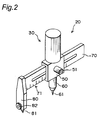
- Figs, 2 to 4 show a compass-cutter 20 according to an embodiment of the present invention.
- Fig. 2 shows a whole perspective view
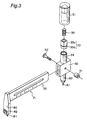
- Fig. 3 shows an exploded perspective view
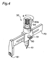
- Fig. 4 shows a partially ruptured perspective view.
- the compass-cutter 20 is used for cutting a paper or a cloth in circular configuration.
- a user sticks the needle 61 at the center of a circle, and pinches a manipulate portion 30 with fingers so as to move a blade 81 along a circular path.
- the manipulate portion 30 is provided with a ratchet mechanism (one-way clutch) therein.
- the ratchet mechanism means what transmits a rotational driving force only in one direction, and the ratchet mechanism itself is known.
- the specific construction of the ratchet mechanism a variety ones are known, and therefore, in the present invention, the specific construction of the ratchet mechanism is not limited to particular one.
- Figs. 3 and 4 are intended to show an example of the ratchet mechanism.
- the first cylindrical member 34 is fixed, so that the compass body 50 and the first cylindrical member 34 can not be relatively rotated.
- the first cylindrical member 34 is provided with teeth at its upper end.
- a member 33 located at upper side of the first cylindrical member 34 comprises an upper square column 33a and a lower second cylindrical member 33b, the column 33a and the member 33b being integrally formed.
- the member 33 is inserted in the body 31 of the manipulate portion with a spring 32 located therebetween.
- Fig. 4 showing an assembled condition, the member 33 is forced downwardly toward the first cylindrical member 34. In this condition, teeth formed at lower end of the second cylindrical member 33b are just fitted with the teeth formed at upper end of the first cylindrical member 34 (refer to Fig. 4).
- the member 33 is connected to the body 31 of the manipulate portion, at its square column 33a, and therefore, the member 33 can not be rotated relatively to the body 31 of the manipulate portion. But, in axial direction, the member 33 can slide relatively to the body 31 of the manipulate portion.
- the spring 32 can be omitted. In Fig. 3, force of the spring 32 pushes the member 33 downwardly toward the first cylindrical member 34. But, if the member 33 itself is relatively heavy, the member 33 would be pressed against the first cylindrical member 34 with self-respect.
- the ratchet mechanism is constituted as above.
- both of the teeth formed on the first cylindrical member 34 and on the second cylindrical member 33b are engaged, so that the blade also rotates in the same direction.
- the manipulate portion 30 is rotated in the direction of "B” in Fig. 4
- the teeth are not engaged and the members 34 and 33b are skidding to each other.
- the blade 81 keeps a constant location.
- the blade 81 is mounted at one end of a horizontal bar 70 via a mount plate 80.
- a screw member 82 is intended for exchanging the blade 81 with another blade.
- the horizontal bar 70 is carried on the compass body 50 so as to slide in horizontal direction.
- the interval between the needle 61 and the blade 81 (namely, the radius of circle) can be adjusted with a bolt 52 and screw member 51.
- the horizontal bar 70 bears a scale 71 for indicating the interval.
- the needle 61 is located co-axially with the manipulate portion 30, and is fix to lower side of the compass body 50 via a shaft member 60.
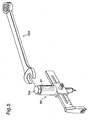
- Fig. 5 there is shown a modification of the compass-cutter 20 described before.
- the head 31a of the body 31 of the manipulate portion is formed in hexagonal configuration.
- the modification has the same ones as those of the compass-cutter 20, and a ratchet mechanism is enclosed in the manipulate portion 30.
- the hexagonal head 31a of the body 31 is to be engaged with a spanner 100. That is, the compass-cutter in Fig. 5 is not intended for using with directly pinching the manipulate portion with fingers, but is intended for using with the spanner 100. Such the modification is effective, when the object to be cut is hard, or the radius of circle is large.
- the head 31a is made hexagonal so as to be engaged with the spanner 100.
- the configuration of the head does not need to be hexagonal, and any suitable configurations (for example, rectangular) can be employed as long as the configurations match with a tool to be used (spanner, monkey wrench, wrench, and so on).
- the configuration can be provided at other location than the head of the body 31.
- the circumferential wall of the body 31 can be partially cut out, so as to be engaged with a tool.
- This compass-cutter 120 comprises a compass body 150 carrying a blade, and a manipulate portion 130 provided with a ratchet mechanism.
- the manipulate portion 130 is detachably connected to the compass body 150.
- the cylindrical member 151 fixed at upper side of the compass body 150 is not provided with a ratchet mechanism, and alternatively, a square recess 152 is formed at the center of the cylindrical member 151.
- a ratchet mechanism is enclosed in the end portion 131 of the manipulate portion 130. From the end portion 131, a square protrusion extends downwardly to be engaged in the square recess 152, though the protrusion does not appear in Fig. 6. With the protrusion (not shown) being engaged in the square recess 152, a user manipulates the handle 132 to cut an object in circular configuration.
- a commercially available tool such as a ratchet handle for socket wrench, can be employed as the manipulate portion 130, and can advantageously lower the manufacturing cost.
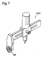
- Figs 7 and 8 show other embodiments of the present invention.
- the blade 81 of the compass-cutter 20 in Fig. 2 is substituted with a rotary blade 85.
- the rotary blade 85 is suitable for thin objects to be cut, such as a cloth.
- a ratchet mechanism is provided to a compass for drawing a circle, and therefore, the blade 81 of the compass-cutter 20 in Fig. 2 is substituted with a pencil 88, which is carried on a horizontal bar.
- a needle (not shown) can be carried on the horizontal bar, and then a circle can be drawn on a metal surface.
- Both of the compass-cutter 220 in Fig. 7 and the compass 320 in Fig.8 are provided with a ratchet mechanism like that employed in the compass-cutter 20 in Fig. 2. Therefore, as a modification of the compass-cutter 220 or the compass 320, the configuration of the manipulate portion thereof can be one adopted to be engaged with a tool. Further, the compass body and the manipulate portion provided with the ratchet mechanism can be separated, like in the above-mentioned.
- ratchet mechanism in the present invention means what transmits a rotational driving force only in one direction, and the specific construction of the ratchet mechanism is not limited to particular one.
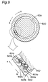
- the mechanism shown in Fig. 9 is so-called a one-way clutch, and this also belongs to the "ratchet mechanism" in the present invention, because the one-way clutch transmits a rotational driving force only in one direction. Note that, the construction of this one-way clutch itself is also known.
- Fig. 9 is a cross sectional view explaining the mechanism of the one-way clutch diagrammatically.
- a center shaft 500 and an outer sheath 600 are arranged co-axially.
- the outer sheath 600 corresponds to the body 31 of the manipulate portion in Fig. 3, and the center shaft 500 is fixed to the compass body 50 (refer to Fig. 3).
- the rotating driving force is transmitted to the center shaft 500 so as to rotate the compass.
- the rotating driving force is not transmitted to the center shaft 500, and thus the outer sheath 600 rotates with skidding. That is, the compass does not rotate and keeps a constant location.
- the principle thereof is as follows.
- the outer sheath 600 carries a plurality of circular columns on its inner surface by means of a holding mechanism (not shown). Although three columns 501, 502, and 503 of them are only shown in Fig. 9, actually a lot of circular columns are arranged along the whole inner surface of the outer sheath 600. Each of the circular columns is held in the gap between the center shaft 500 and the outer sheath 600, with its longitudinal axis being parallel to the axes of the center shaft 500 and the outer sheath 600.
- each of the recesses comprises a gentle first slope 601a, 602a, 603a and a steep second slope 601b, 602b, 603b.
- Each of the circular columns 501, 502, 503 is forced in the direction "A" by a spring (not shown and held at the outer sheath 600).
- each of the circular columns 501, 502, 503 follows the gentle first slope 601a, 602a, 603a under the urging force of the spring.
- each of the circular columns 501, 502, 503 is pressed against the gentle first slope 601a, 602a, 603a under the urging force of the spring.
- the diameter of individual circular column is set larger than the gap between the center shaft 500 and the outer sheath 600, each of the circular columns 501, 502, 503 bites into the wedged-space between the gentle first slope and the outer surface of the center shaft 500, so that the rotational torque applied to the outer sheath 600 is transmitted, via the circular columns, to the center shaft 500, and therefore, the compass rotates.
- Fig. 10 shows a compass-cutter according to another embodiment of the present invention.
- the manipulate portion 960 of this compass-cutter is provided with the same ratchet mechanism as that employed in the compass shown in Figs. 2 to 4, and is fixed to a compass body 950.
- a needle 701 defining the rotation center of the compass is not fixed to the compass body 950, but is fixed to an distal end of a shaft member (first leg) 700.
- the shaft member extends downwardly from a slide member 750 which is separated from the compass body 950.
- both of the compass body 950 and the slide member 750 can slide along a horizontal bar (lateral bar) 900, and fixed at any position as desired.
- the mechanism therefor is the same as that employed in the embodiment in Fig. 3.
- the manipulate portion 960 can be always located at intermediate position between the rotation center (the position of the needle 701) and the blade 801, regardless of the interval length between the rotation center (the position of the needle 701) and the blade 801. Further, sliding in parallel the slide member 750 along the horizontal bar 900, the rotation radius of the blade 801 fixed to the mount plate (second leg) 800 can be adjusted, and the rotating plane of the blade 801 is always kept in parallel to the center axis of the needle 701.
- Such the construction is particularly advantageous in a compass-cutter wherein a blade is utilized for cutting an object in circular configuration. This is explained below.
- a blade is set to one leg of a compass as shown in Fig. 1, in which the rotation radius is adjusted with an open angle between two legs 11 and 15.
- the angle between the rotating plane of the blade and the axis of the needle 12 also changes.
- the relative angle of the rotating plane of the blade to the surface of the object to be cut changes, and means that depending on the relative angle value (in other words, depending on the rotation radius), smooth cutting operation just along a desired cutting line may be prevented.
- the rotating plane of the blade 801 can be always kept in parallel to the axis of the needle 701, regardless of the interval length between the rotation center (the position of the needle 701) and the blade 801. As a result, the rotating plane of the blade 801 can be always kept in a nearly right angle to the object to be cut, regardless of the rotation radius.
- the manipulate portion 960 can be always located at intermediate position between the rotation center (the position of the needle 701) and the blade 801, it is possible to deliver the pushing force transmitted from user's hand almost equally to the needle 701 and to the blade 801. This is true when the rotary blade 801 in Fig. 10 is substituted with the stationary blade 81 in Fig. 2.
- a rod 981 is stationary fixed to the compass-body 950.
- a treaded end portion 982 of the rod 981 passes through an opening 991 formed on an upper wall of a sheath 990, and a nut 983 is engaged with the treaded end portion 982.
- the sheath 990 is attached to the rod 981 so as to freely rotate in both directions.
- the cutting operation with the rotary blade 801 is to be conducted by revolving use's hand holding the sheath 990 around the needle 701.
- the cutting operation can be conducted in both of left and right directions; the cutting operation can be easily conducted regardless of a left-handed user or a right-handed user; and the manipulate portion can be simplified compared as the embodiment employing the ratchet mechanism.
- the manipulate portion comprises one rod 955, which is stationary fixed to the compass body 950.
- This construction is inferior to the construction in Fig. 13 in view of the easy operation, but brings a merit that the construction is further simplified.
- the rotary blade 801 can be substituted with the blade 81 such as shown in Fig. 2, or with the pencil 88 such as shown in Fig. 8.
- Figs. 10 and 11 modifications to the compass-cutter in Fig. 10 are shown. Both of the modifications are provided with a mechanism, with which a user can easily locate the manipulate portion at intermediate position between the rotation center and the blade (center-positioning).
- the center-positioning of the manipulate portion 960 can be done with utilizing springs 965 and 966.
- the springs 965 and 966 are accommodated in an elongated opening 901 which is formed along the longitudinal direction of a horizontal bar 900.
- One end 965a of the spring 965 (second spring) is fixed to the left end 901a (in Fig. 11) of the elongated opening, and the other end 965b is fixed to a fix pin 955 arranged on the compass body 950.
- one end 966a of the spring 966 (first spring) is fixed to the fix pin 955, and the other end 966b is fixed to a fix pin 755 arranged on the slide member 750.
- Two springs 965 and 966 have the equal spring-rate.
- the mount plate (first leg) 800 is directly attached to the horizontal bar 900, and one end 965a of the spring 965 is connected directly to the horizontal bar itself.
- the manipulate portion 960 and the mount plate 800 are connected via the spring 965.
- the mount plate 800 may be made to be able to freely slide relative to the horizontal bar 900, and one end 965a of the spring 965 may be attached to such the mount plate 800, like in the embodiment in Fig. 12.
- a screw member 970 is utilized to conduct the center-positioning of the manipulate portion 960.
- the screw member 970 comprises a center-located dial portion 971, a left screw 972 and a right screw 973, the screws 972 and 973 projecting opposite from the dial portion 971 co-axially.
- the screw member 970 is located in an elongated opening 902 formed along the longitudinal direction of the horizontal bar 900, and the dial portion 971 is exposed to outward through a slit formed on the compass body 950a.
- the mount plate 800 carrying the blade 801 is fixed to a slide member 800a, and engaged with the left screw 972 via the slide member 800a. That is, the slide member 800a is provided with a threaded portion (not shown) therein, and this threaded portion is engaged with the left screw 972. On the other hand, the slide member 750a carrying the needle 701 is provided with a threaded portion (not shown) therein, and this threaded portion is engaged with the right screw 973.
- the manipulate portion 960 can be positioned at the intermediate position between the rotation center and the blade can be secured, easily and securely.
Landscapes
- Knives (AREA)
Priority Applications (1)
| Application Number | Priority Date | Filing Date | Title |
|---|---|---|---|
| EP07121557A EP1892119A1 (fr) | 2001-09-25 | 2002-09-23 | Compas de coupe |
Applications Claiming Priority (6)
| Application Number | Priority Date | Filing Date | Title |
|---|---|---|---|
| JP2001291444 | 2001-09-25 | ||
| JP2001291444 | 2001-09-25 | ||
| JP2002103759 | 2002-04-05 | ||
| JP2002103759 | 2002-04-05 | ||
| JP2002187806 | 2002-06-27 | ||
| JP2002187806A JP3716232B2 (ja) | 2001-09-25 | 2002-06-27 | ラチェット機構付きのコンパスおよびコンパスカッター |
Related Child Applications (2)
| Application Number | Title | Priority Date | Filing Date |
|---|---|---|---|
| EP07121557A Division EP1892119A1 (fr) | 2001-09-25 | 2002-09-23 | Compas de coupe |
| EP07121557A Division-Into EP1892119A1 (fr) | 2001-09-25 | 2002-09-23 | Compas de coupe |
Publications (3)
| Publication Number | Publication Date |
|---|---|
| EP1295736A2 true EP1295736A2 (fr) | 2003-03-26 |
| EP1295736A3 EP1295736A3 (fr) | 2003-07-16 |
| EP1295736B1 EP1295736B1 (fr) | 2015-04-22 |
Family
ID=27347568
Family Applications (2)
| Application Number | Title | Priority Date | Filing Date |
|---|---|---|---|
| EP07121557A Withdrawn EP1892119A1 (fr) | 2001-09-25 | 2002-09-23 | Compas de coupe |
| EP20020256597 Expired - Lifetime EP1295736B1 (fr) | 2001-09-25 | 2002-09-23 | Compas-cutter avec mécanisme à encliquetage |
Family Applications Before (1)
| Application Number | Title | Priority Date | Filing Date |
|---|---|---|---|
| EP07121557A Withdrawn EP1892119A1 (fr) | 2001-09-25 | 2002-09-23 | Compas de coupe |
Country Status (4)
| Country | Link |
|---|---|
| US (2) | US6889440B2 (fr) |
| EP (2) | EP1892119A1 (fr) |
| JP (1) | JP3716232B2 (fr) |
| CA (1) | CA2404640C (fr) |
Cited By (3)
| Publication number | Priority date | Publication date | Assignee | Title |
|---|---|---|---|---|
| CN103950324A (zh) * | 2014-04-30 | 2014-07-30 | 电子科技大学 | 便携式四自由度教学圆规 |
| FR3077029A1 (fr) * | 2018-01-24 | 2019-07-26 | Maped | Compas de dessin |
| CN113524819A (zh) * | 2021-06-01 | 2021-10-22 | 江苏斯凯氟复合材料有限公司 | 一种多功能玻璃纤维硅胶布 |
Families Citing this family (26)
| Publication number | Priority date | Publication date | Assignee | Title |
|---|---|---|---|---|
| US6941605B2 (en) * | 2003-08-12 | 2005-09-13 | Derry Industries, Llc | Multi-purpose hand tool and scribing apparatus utilizing multi-purpose hand tool |
| WO2006014192A2 (fr) * | 2004-04-15 | 2006-02-09 | Nomis, Llc | Rail de guidage reglable pour outils a main |
| US20100018062A1 (en) * | 2004-10-15 | 2010-01-28 | Stravitz David M | Fashioning Devices |
| US7591072B2 (en) * | 2004-10-15 | 2009-09-22 | Stravitz David M | Cutting devices |
| US7281803B2 (en) * | 2004-11-12 | 2007-10-16 | Infocus Corporation | Polarization conversion assembly to complement angular transmission distribution of polarizing light modulator |
| US20060207114A1 (en) * | 2005-03-16 | 2006-09-21 | Stoner Arthur G | Drafting compass |
| WO2010048643A2 (fr) * | 2008-10-24 | 2010-04-29 | Regina Yoder | Dispositif de coupe circulaire et outil comprenant une équerre en t |
| US20100263556A1 (en) * | 2009-04-16 | 2010-10-21 | Grigore Axinte | Rolling Cookie, Pastry, Pizza, and Pasta Tool |
| US8302274B1 (en) * | 2010-03-01 | 2012-11-06 | Dominique Depaz | Blade removal assistance tool system |
| FR2959156B1 (fr) * | 2010-04-21 | 2012-09-21 | Benoit Mallet | Guide de decoupe d'un panneau de carton-platre, kit et procede de mise en oeuvre |
| TWI498231B (zh) * | 2012-10-11 | 2015-09-01 | Surbright Entpr Co Ltd | 可替換刀件之圓規刀 |
| US9592622B2 (en) * | 2013-10-25 | 2017-03-14 | Gracewood Management, Inc. | Circle cutter for fabric |
| CN203696993U (zh) * | 2013-11-26 | 2014-07-09 | 河南省水利科学研究院 | 一种划线器 |
| USD792516S1 (en) * | 2015-10-01 | 2017-07-18 | Maped | Compass head |
| CN105904887A (zh) * | 2016-04-27 | 2016-08-31 | 张海燕 | 多功能木工圆规尺 |
| USD823389S1 (en) * | 2016-10-27 | 2018-07-17 | Beifa Group Co., Ltd. | Compass |
| CN106494135A (zh) * | 2016-11-05 | 2017-03-15 | 刘志明 | 一种新型圆规 |
| KR200487383Y1 (ko) * | 2016-11-10 | 2018-10-22 | 김영진 | 컴퍼스 |
| CN107089081B (zh) * | 2017-04-28 | 2018-06-22 | 郑州航空工业管理学院 | 数学绘图仪 |
| CN107139613B (zh) * | 2017-04-28 | 2018-05-08 | 郑州航空工业管理学院 | 一种数学教学辅助用装置 |
| TWI619587B (zh) * | 2017-05-26 | 2018-04-01 | 羅士硯 | 切割裝置 |
| TWI628708B (zh) * | 2017-07-03 | 2018-07-01 | 國立臺灣師範大學 | 切割圓形的切割裝置 |
| JP6622439B1 (ja) * | 2019-03-06 | 2019-12-18 | 住友化学株式会社 | 切削加工された積層フィルムの製造方法 |
| CN110877131A (zh) * | 2019-10-29 | 2020-03-13 | 沪东中华造船(集团)有限公司 | 一种圆孔手工割制方法 |
| CN111301032A (zh) * | 2020-03-27 | 2020-06-19 | 西安石油大学 | 一种圆规装置 |
| US11953319B2 (en) * | 2021-01-22 | 2024-04-09 | Macario A. Sanchez | Sliding adjustable compass having a support |
Citations (2)
| Publication number | Priority date | Publication date | Assignee | Title |
|---|---|---|---|---|
| US4822284A (en) | 1988-07-25 | 1989-04-18 | Cohen Martha G | Educational appliance for teaching handwriting skills |
| GB2285594A (en) | 1994-01-14 | 1995-07-19 | Arwell Williams | Bevel cutter |
Family Cites Families (25)
| Publication number | Priority date | Publication date | Assignee | Title |
|---|---|---|---|---|
| US677339A (en) * | 1900-11-01 | 1901-07-02 | Edwin M Comstock | Center punch and gage. |
| US800257A (en) * | 1904-12-05 | 1905-09-26 | Adolph E Abetz | Compass leg and point. |
| US1628426A (en) | 1925-02-12 | 1927-05-10 | Antoine E M Prenveille | Beam compass |
| US2309809A (en) * | 1941-05-26 | 1943-02-02 | Vane Howard Hollis | Geometrical instrument |
| FR933784A (fr) | 1946-09-21 | 1948-04-30 | Système de compas à allonge | |
| US2499673A (en) * | 1948-04-05 | 1950-03-07 | Stephen J Olejniczak | Rule compass |
| US2534440A (en) * | 1948-07-30 | 1950-12-19 | Joseph Blasig | Beam compass |
| US2768443A (en) * | 1955-09-28 | 1956-10-30 | Chiaravalloti Nicola | Beam compass for marking and cutting |
| US3292262A (en) | 1965-08-18 | 1966-12-20 | Worth J Moll | Beam compass |
| GB1375155A (fr) | 1973-02-19 | 1974-11-27 | ||
| US3925898A (en) * | 1974-07-29 | 1975-12-16 | George Melnik | Ruler-beam |
| US4656744A (en) * | 1985-01-29 | 1987-04-14 | Decker Henry P | Scribing tool for wall panels and the like |
| US4662073A (en) * | 1986-03-13 | 1987-05-05 | David Prusman | Infinitely variable drawing instrument |
| US4976037A (en) * | 1988-03-21 | 1990-12-11 | Hines Burl D | Marking and cutting device |
| US4923407A (en) * | 1989-10-02 | 1990-05-08 | Tektronix, Inc. | Adjustable low inductance probe |
| DE8912735U1 (fr) * | 1989-10-27 | 1991-03-14 | Schifferdecker, Mathias, 6967 Buchen, De | |
| US5233715A (en) * | 1992-11-24 | 1993-08-10 | Huang Ming Tzung | Combination tool assembly for graphic art |
| US5542185A (en) * | 1994-04-15 | 1996-08-06 | Fiskars Inc. | Device for describing arcs |
| US5596809A (en) * | 1995-12-27 | 1997-01-28 | Beard; Jay T. | Circle cutter for drywall with measure guide |
| US5895183A (en) * | 1997-03-25 | 1999-04-20 | Mcdaniel; Jamie | Circular hole cutter |
| DE29706392U1 (de) | 1997-04-10 | 1997-06-05 | Schuffenhauer Joerg Dipl Ing | Stangenzirkel mit auswechselbaren Schreib- und Anreißeinsätzen |
| US6167628B1 (en) * | 1998-08-27 | 2001-01-02 | Lee Valley Tools, Ltd. | Carpenter's gauge |
| US6311404B1 (en) * | 1998-10-30 | 2001-11-06 | Paul A. Smith | Retractable safety mechanism and compass and method of using the same |
| US6276067B1 (en) * | 2000-01-13 | 2001-08-21 | Welter's Co., Ltd. | Ellipse drawing/cutting device |
| US6546634B2 (en) * | 2000-12-29 | 2003-04-15 | Chen Shan Ming | Compass cutter |
-
2002
- 2002-06-27 JP JP2002187806A patent/JP3716232B2/ja not_active Expired - Lifetime
- 2002-09-20 US US10/247,710 patent/US6889440B2/en not_active Expired - Lifetime
- 2002-09-23 EP EP07121557A patent/EP1892119A1/fr not_active Withdrawn
- 2002-09-23 CA CA002404640A patent/CA2404640C/fr not_active Expired - Lifetime
- 2002-09-23 EP EP20020256597 patent/EP1295736B1/fr not_active Expired - Lifetime
-
2004
- 2004-12-29 US US11/023,600 patent/US6983545B2/en not_active Expired - Lifetime
Patent Citations (2)
| Publication number | Priority date | Publication date | Assignee | Title |
|---|---|---|---|---|
| US4822284A (en) | 1988-07-25 | 1989-04-18 | Cohen Martha G | Educational appliance for teaching handwriting skills |
| GB2285594A (en) | 1994-01-14 | 1995-07-19 | Arwell Williams | Bevel cutter |
Cited By (4)
| Publication number | Priority date | Publication date | Assignee | Title |
|---|---|---|---|---|
| CN103950324A (zh) * | 2014-04-30 | 2014-07-30 | 电子科技大学 | 便携式四自由度教学圆规 |
| FR3077029A1 (fr) * | 2018-01-24 | 2019-07-26 | Maped | Compas de dessin |
| EP3517312A3 (fr) * | 2018-01-24 | 2019-10-16 | Maped | Compas de dessin |
| CN113524819A (zh) * | 2021-06-01 | 2021-10-22 | 江苏斯凯氟复合材料有限公司 | 一种多功能玻璃纤维硅胶布 |
Also Published As
| Publication number | Publication date |
|---|---|
| US20030056378A1 (en) | 2003-03-27 |
| US6983545B2 (en) | 2006-01-10 |
| JP3716232B2 (ja) | 2005-11-16 |
| EP1892119A1 (fr) | 2008-02-27 |
| US20050108883A1 (en) | 2005-05-26 |
| CA2404640A1 (fr) | 2003-03-25 |
| EP1295736B1 (fr) | 2015-04-22 |
| US6889440B2 (en) | 2005-05-10 |
| JP2004001336A (ja) | 2004-01-08 |
| EP1295736A3 (fr) | 2003-07-16 |
| CA2404640C (fr) | 2006-06-13 |
Similar Documents
| Publication | Publication Date | Title |
|---|---|---|
| EP1295736A2 (fr) | Compas et compas-cutter avec mécanisme à encliquetage | |
| JP4291882B2 (ja) | 多機能工具 | |
| US6095018A (en) | Rotary hand tool with a crank arm incorporated into its handle | |
| US2712765A (en) | Wrist-motion rotary hand-tool | |
| US20070034060A1 (en) | Screw guide device | |
| JPH07100801A (ja) | プランジ型ルータ | |
| US4196761A (en) | Screw driver with retractable lever attachment | |
| US20180116703A1 (en) | Device for handling a bone screw | |
| KR980700900A (ko) | 미늘톱니렌치(ratchet wrench) | |
| CA2510543C (fr) | Couteau compas | |
| US2604693A (en) | Dental finishing tool | |
| US6457385B1 (en) | Precision driver rotation structure | |
| JP2005246098A (ja) | コンパスカッター | |
| US2277961A (en) | Brace | |
| US2464372A (en) | Torque measuring screw driver | |
| US4005622A (en) | Circular saw wrench | |
| CA1143188A (fr) | Perceuse-taraudeuse | |
| US4590824A (en) | Screwdriver | |
| CN105382769A (zh) | 电动工具 | |
| US20200060788A1 (en) | Hand operated dental instrument | |
| US20240181605A1 (en) | Cable tie plier | |
| JP2002307317A (ja) | 先端回転型ペンチ | |
| JPH01108130A (ja) | ガラスカッター及びガラス切刻方法 | |
| US946896A (en) | Tool-handle and tool-handle fastening. | |
| JPS5822695Y2 (ja) | カツタ−ホルダ− |
Legal Events
| Date | Code | Title | Description |
|---|---|---|---|
| PUAI | Public reference made under article 153(3) epc to a published international application that has entered the european phase |
Free format text: ORIGINAL CODE: 0009012 |
|
| 17P | Request for examination filed |
Effective date: 20021004 |
|
| AK | Designated contracting states |
Kind code of ref document: A2 Designated state(s): AT BE BG CH CY CZ DE DK EE ES FI FR GB GR IE IT LI LU MC NL PT SE SK TR Designated state(s): AT BE BG CH CY CZ DE DK EE ES FI FR GB GR IE IT LI LU MC NL PT SE SK TR |
|
| AX | Request for extension of the european patent |
Extension state: AL LT LV MK RO SI |
|
| PUAL | Search report despatched |
Free format text: ORIGINAL CODE: 0009013 |
|
| AK | Designated contracting states |
Designated state(s): AT BE BG CH CY CZ DE DK EE ES FI FR GB GR IE IT LI LU MC NL PT SE SK TR |
|
| AX | Request for extension of the european patent |
Extension state: AL LT LV MK RO SI |
|
| AKX | Designation fees paid |
Designated state(s): DE FR GB IT |
|
| 17Q | First examination report despatched |
Effective date: 20070618 |
|
| GRAP | Despatch of communication of intention to grant a patent |
Free format text: ORIGINAL CODE: EPIDOSNIGR1 |
|
| INTG | Intention to grant announced |
Effective date: 20150126 |
|
| GRAS | Grant fee paid |
Free format text: ORIGINAL CODE: EPIDOSNIGR3 |
|
| GRAA | (expected) grant |
Free format text: ORIGINAL CODE: 0009210 |
|
| AK | Designated contracting states |
Kind code of ref document: B1 Designated state(s): DE FR GB IT |
|
| REG | Reference to a national code |
Ref country code: GB Ref legal event code: FG4D |
|
| REG | Reference to a national code |
Ref country code: DE Ref legal event code: R096 Ref document number: 60247130 Country of ref document: DE Effective date: 20150603 |
|
| REG | Reference to a national code |
Ref country code: DE Ref legal event code: R097 Ref document number: 60247130 Country of ref document: DE |
|
| PLBE | No opposition filed within time limit |
Free format text: ORIGINAL CODE: 0009261 |
|
| STAA | Information on the status of an ep patent application or granted ep patent |
Free format text: STATUS: NO OPPOSITION FILED WITHIN TIME LIMIT |
|
| 26N | No opposition filed |
Effective date: 20160125 |
|
| REG | Reference to a national code |
Ref country code: FR Ref legal event code: PLFP Year of fee payment: 15 |
|
| REG | Reference to a national code |
Ref country code: FR Ref legal event code: PLFP Year of fee payment: 16 |
|
| REG | Reference to a national code |
Ref country code: FR Ref legal event code: PLFP Year of fee payment: 17 |
|
| PGFP | Annual fee paid to national office [announced via postgrant information from national office to epo] |
Ref country code: IT Payment date: 20210906 Year of fee payment: 20 Ref country code: FR Payment date: 20210726 Year of fee payment: 20 |
|
| PGFP | Annual fee paid to national office [announced via postgrant information from national office to epo] |
Ref country code: GB Payment date: 20210924 Year of fee payment: 20 Ref country code: DE Payment date: 20210914 Year of fee payment: 20 |
|
| REG | Reference to a national code |
Ref country code: DE Ref legal event code: R071 Ref document number: 60247130 Country of ref document: DE |
|
| REG | Reference to a national code |
Ref country code: GB Ref legal event code: PE20 Expiry date: 20220922 |
|
| PG25 | Lapsed in a contracting state [announced via postgrant information from national office to epo] |
Ref country code: GB Free format text: LAPSE BECAUSE OF EXPIRATION OF PROTECTION Effective date: 20220922 |