EP1294471B1 - System zur erfassung von verlust und wirkungsgrad der katalytische beschichtung - Google Patents
System zur erfassung von verlust und wirkungsgrad der katalytische beschichtung Download PDFInfo
- Publication number
- EP1294471B1 EP1294471B1 EP01937570A EP01937570A EP1294471B1 EP 1294471 B1 EP1294471 B1 EP 1294471B1 EP 01937570 A EP01937570 A EP 01937570A EP 01937570 A EP01937570 A EP 01937570A EP 1294471 B1 EP1294471 B1 EP 1294471B1
- Authority
- EP
- European Patent Office
- Prior art keywords
- catalyst
- radiator
- catalyst coating
- light
- ozone
- Prior art date
- Legal status (The legal status is an assumption and is not a legal conclusion. Google has not performed a legal analysis and makes no representation as to the accuracy of the status listed.)
- Expired - Lifetime
Links
Images




Classifications
-
- F—MECHANICAL ENGINEERING; LIGHTING; HEATING; WEAPONS; BLASTING
- F01—MACHINES OR ENGINES IN GENERAL; ENGINE PLANTS IN GENERAL; STEAM ENGINES
- F01N—GAS-FLOW SILENCERS OR EXHAUST APPARATUS FOR MACHINES OR ENGINES IN GENERAL; GAS-FLOW SILENCERS OR EXHAUST APPARATUS FOR INTERNAL-COMBUSTION ENGINES
- F01N11/00—Monitoring or diagnostic devices for exhaust-gas treatment apparatus
-
- B—PERFORMING OPERATIONS; TRANSPORTING
- B01—PHYSICAL OR CHEMICAL PROCESSES OR APPARATUS IN GENERAL
- B01J—CHEMICAL OR PHYSICAL PROCESSES, e.g. CATALYSIS OR COLLOID CHEMISTRY; THEIR RELEVANT APPARATUS
- B01J23/00—Catalysts comprising metals or metal oxides or hydroxides, not provided for in group B01J21/00
- B01J23/16—Catalysts comprising metals or metal oxides or hydroxides, not provided for in group B01J21/00 of arsenic, antimony, bismuth, vanadium, niobium, tantalum, polonium, chromium, molybdenum, tungsten, manganese, technetium or rhenium
- B01J23/32—Manganese, technetium or rhenium
- B01J23/34—Manganese
-
- F—MECHANICAL ENGINEERING; LIGHTING; HEATING; WEAPONS; BLASTING
- F01—MACHINES OR ENGINES IN GENERAL; ENGINE PLANTS IN GENERAL; STEAM ENGINES
- F01P—COOLING OF MACHINES OR ENGINES IN GENERAL; COOLING OF INTERNAL-COMBUSTION ENGINES
- F01P11/00—Component parts, details, or accessories not provided for in, or of interest apart from, groups F01P1/00 - F01P9/00
- F01P11/14—Indicating devices; Other safety devices
-
- B—PERFORMING OPERATIONS; TRANSPORTING
- B01—PHYSICAL OR CHEMICAL PROCESSES OR APPARATUS IN GENERAL
- B01D—SEPARATION
- B01D2259/00—Type of treatment
- B01D2259/45—Gas separation or purification devices adapted for specific applications
- B01D2259/455—Gas separation or purification devices adapted for specific applications for transportable use
- B01D2259/4558—Gas separation or purification devices adapted for specific applications for transportable use for being employed as mobile cleaners for ambient air, i.e. the earth's atmosphere
-
- F—MECHANICAL ENGINEERING; LIGHTING; HEATING; WEAPONS; BLASTING
- F01—MACHINES OR ENGINES IN GENERAL; ENGINE PLANTS IN GENERAL; STEAM ENGINES
- F01N—GAS-FLOW SILENCERS OR EXHAUST APPARATUS FOR MACHINES OR ENGINES IN GENERAL; GAS-FLOW SILENCERS OR EXHAUST APPARATUS FOR INTERNAL-COMBUSTION ENGINES
- F01N2550/00—Monitoring or diagnosing the deterioration of exhaust systems
- F01N2550/02—Catalytic activity of catalytic converters
-
- F—MECHANICAL ENGINEERING; LIGHTING; HEATING; WEAPONS; BLASTING
- F01—MACHINES OR ENGINES IN GENERAL; ENGINE PLANTS IN GENERAL; STEAM ENGINES
- F01N—GAS-FLOW SILENCERS OR EXHAUST APPARATUS FOR MACHINES OR ENGINES IN GENERAL; GAS-FLOW SILENCERS OR EXHAUST APPARATUS FOR INTERNAL-COMBUSTION ENGINES
- F01N2550/00—Monitoring or diagnosing the deterioration of exhaust systems
- F01N2550/24—Determining the presence or absence of an exhaust treating device
-
- F—MECHANICAL ENGINEERING; LIGHTING; HEATING; WEAPONS; BLASTING
- F01—MACHINES OR ENGINES IN GENERAL; ENGINE PLANTS IN GENERAL; STEAM ENGINES
- F01P—COOLING OF MACHINES OR ENGINES IN GENERAL; COOLING OF INTERNAL-COMBUSTION ENGINES
- F01P2025/00—Measuring
-
- F—MECHANICAL ENGINEERING; LIGHTING; HEATING; WEAPONS; BLASTING
- F01—MACHINES OR ENGINES IN GENERAL; ENGINE PLANTS IN GENERAL; STEAM ENGINES
- F01P—COOLING OF MACHINES OR ENGINES IN GENERAL; COOLING OF INTERNAL-COMBUSTION ENGINES
- F01P2031/00—Fail safe
- F01P2031/20—Warning devices
-
- Y—GENERAL TAGGING OF NEW TECHNOLOGICAL DEVELOPMENTS; GENERAL TAGGING OF CROSS-SECTIONAL TECHNOLOGIES SPANNING OVER SEVERAL SECTIONS OF THE IPC; TECHNICAL SUBJECTS COVERED BY FORMER USPC CROSS-REFERENCE ART COLLECTIONS [XRACs] AND DIGESTS
- Y02—TECHNOLOGIES OR APPLICATIONS FOR MITIGATION OR ADAPTATION AGAINST CLIMATE CHANGE
- Y02T—CLIMATE CHANGE MITIGATION TECHNOLOGIES RELATED TO TRANSPORTATION
- Y02T10/00—Road transport of goods or passengers
- Y02T10/10—Internal combustion engine [ICE] based vehicles
- Y02T10/40—Engine management systems
-
- Y—GENERAL TAGGING OF NEW TECHNOLOGICAL DEVELOPMENTS; GENERAL TAGGING OF CROSS-SECTIONAL TECHNOLOGIES SPANNING OVER SEVERAL SECTIONS OF THE IPC; TECHNICAL SUBJECTS COVERED BY FORMER USPC CROSS-REFERENCE ART COLLECTIONS [XRACs] AND DIGESTS
- Y10—TECHNICAL SUBJECTS COVERED BY FORMER USPC
- Y10T—TECHNICAL SUBJECTS COVERED BY FORMER US CLASSIFICATION
- Y10T436/00—Chemistry: analytical and immunological testing
- Y10T436/13—Tracers or tags
Definitions
- This invention relates generally to a method for determining the efficiency of a catalyst coating and more particularly to a method for determining the effectiveness of a catalyst based ozone depletion system.
- the invention is particularly applicable to and will be described with specific reference to an on-board diagnostic system determining failure of an ozone depletion system applied to heat exchange surfaces in a vehicle and indicating such failure to the vehicle's operator.
- the invention is believed to have broader application and could be employed to determine the conversion efficiency of a stationary system using a catalyst based ozone depletion system such as heat exchanges or HVAC systems in residential, commercial or industrial facilities.
- the invention is also believed to have application to certain catalyst formulations, other than those utilized in an ozone depletion system, but which have distinguishing performance characteristics similar to those of a catalyst based ozone depletion system.
- ground-level ozone O 3
- ozone is produced by complex chemical reactions when its precursors such as VOC (volatile organic compounds) and NOx (nitrogen oxides) react in the presence of sunlight.
- VOC volatile organic compounds
- NOx nitrogen oxides
- the EPA in implementing the provisions of the United States Clean Air Act, has identified 26 metropolitan areas within the United States which its modeling techniques show have or will exceed National Ambient Air Quality Standards for ozone in the near future. Accordingly, the EPA has promulgated increasingly tighter emission regulations directed to limiting emissions from vehicles which promote ozone formation.
- the assignee has determined that vehicles having radiators and/or air conditioning units operate at slightly elevated temperatures from ambient whereat the ozone depleting catalysts formulated by assignee are especially effective in converting ozone to oxygen while exhibiting characteristics allowing the catalyst to adhere to vibrating surfaces and function in the harsh environment that a motor vehicle is subjected to.
- the assignee of this invention has marketed its ozone depleting substances under its PremAir® brand name.
- OBD on-board diagnostic
- the most effective way to determine the functioning of an ozone depletion system is to measure the ozone concentration in the atmospheric air stream upstream and downstream of the ozone depletion system. The difference between the measurements provides an accurate "count” of the quantity of ozone removed from the atmospheric air stream passing through the ozone depleting system.
- Another type of OBD system is widely used to determine the functioning of the typical TWC catalyst (three way catalyst) for removing HC (hydrocarbons) in that oxygen sensors, upstream and downstream of the TWC catalyst, sense upstream and downstream oxygen concentrations in the exhaust gas to estimate a storage capacity of the TWC catalyst which in turn is correlated to the efficiency at which the TWC catalyst converts certain noxious emissions.
- a direct ozone sensing approach will not practically function today as an OBD system to measure the effectiveness of an ozone depletion system installed on a moving vehicle for several reasons.
- the ozone concentration that is being sensed is small and variable. For example, standard regulatory limits are 0.12 ppm over one hour with proposed regulations reducing the exposure to 0.08 ppm over an 8 hour period. Even in high smog concentration areas, such as Los Angeles, ground level ozone concentration may reach 0.20 ppm during summer, daytime hours and 0.01-0.02 ppm during nightime.
- the ozone sensor has to therefore have a sensitivity sufficient to detect and measure minute quantities of ozone present in a moving gas stream.
- United States patent 5,972,714 to Roland et al discloses an ozone sensor measuring microcracks caused in an elastomeric material to determine the presence of ozone at sampling times in the range of 10-15 minutes. While a definite improvement, such sensor would not function as an OBD detector in the automotive environment.
- the sensor art is a developed and refined field applied in any number of applications.
- USUPA ultrasonic impedance is measured to determine characteristics of a material including the density of the material, the level of material in a container, interface position between materials of different density, material hardness, particle and changes in chemical composition such as changes in physical/chemical characteristics i.e, density used to monitor the curing of resins, concrete and similar materials.
- a proximity sensor utilizing a capacitor determines the presence or absence of a material.
- a fluorophore is added to or chemically attached to a curable release coating applied to a substrate and exposed to an ultraviolet light source to monitor the cure of coated substrates such as silicone release liners.
- a number of the mentioned prior art sensors and systems are not of the type that can be readily implemented in or are suitable for inclusion on a vehicle as an OBD system. i.e., x-ray attenuation measurements.
- Many of the sensor systems are active, particularly the curing arrangements, in that a chemical reaction is forced to occur which results in a sudden physical change in state that is detected. That is the sensors disclosed are not shown or disclosed as suitable for use in a method whereat the sensor is detecting a physical aging characteristic of the catalyst correlated to a chemical active state of the catalyst or a method whereat a physical wearing away of the catalyst is detected relative to a normally aged chemical condition of the catalyst.
- EP 1 153 647 A1 was published on 14th November 2001 and discloses a motor vehicle comprising an engine, a cooling circuit connected to the engine provided with a heat exchanging member which is at least partially externally coated with catalyst material for conversion of substances harmful to the environment in ambient air.
- the motor vehicle further comprises a control unit to which detecting means are connected for estimating and/or determining the degree of conversion, of a substance harmful to the environment, of the heat exchanging member with the catalytic coating.
- the method can include the steps or acts of a) providing a sensor generating signals indicative of a physical characteristic of the catalyst; b) setting a threshold against which the sensor signals are compared, the threshold indicative of the chemical conversion efficiency at which the catalyst reacts with the fluid stream when the catalyst normally ages to approach a steady state conversion efficiency; c) determining from the deviation between the sensor signal and the threshold signal when the sensor signal drops below the threshold signal the quantity of catalyst present on the substrate; and d) activating a warning when the quantity of catalyst present, as determined in step (c) drops below a set value.
- a method or system for determining if a vehicular ozone depletion system is functioning to remove ozone from atmospheric air.
- the ozone depletion system includes a catalyst containing MnO 2 applied as a coating to a heat exchange surface in the vehicle over which atmospheric air passes. The method includes the steps of:
- the method includes the step of sensing a physical characteristic of the catalyst coating to determines i) not only its presence or absence from the heat exchange surface to determine a nonfunctioning ozone depletion system, but ii), optionally, or in addition, the relative efficiency of the ozone depletion system to convert ozone to a benign chemical or compound to determine a catastrophic failure of the ozone depletion system.
- the sensing step can include sensing a physical characteristic of the catalyst coating selected from the group consisting of electrical conductivity, radiation absorption, radiation emission and radiation transmission whereby optical, electrical and combined optical and electrical OBD systems can be constructed to determine whether an ozone removal system based on a catalyst coating is functioning and/or measure the efficiency of the ozone removal system.
- the sensing step includes the steps of providing an electrical power supply; connecting the power supply to an electrical circuit extending through a portion of the catalyst coating to cause electrons to flow through a portion of the catalyst coating when the power supply is activated; and, sensing a change or an absolute value in one or more circuit parameters selected from the group consisting of voltage, resistance or current to determine when the catalyst coating is no longer present.
- the present method suitably comprises the steps of:
- the heat exchanger surface is suitably a vehicular radiator.
- the sensor is an electrical sensor
- the physical characteristic is moisture present in the catalyst of the coating and said method includes the steps of sampling the sensor signals at different temperatures of the coating and comparing the signals at the different temperatures to measure resistance changes in the coating as moisture is released from the coating.
- a method for determining when a catalyst coating containing MnO 2 applied as a thin layer to the fins of a vehicular radiator ceases to remove ozone from atmospheric air passing through the radiator during the life of the radiator.
- the method includes the steps of providing an insulated conductor having insulation partially removed over an exposed section.
- the insulated conductor is embedded within the catalyst coating so that the conductor insulation is in contact with (or closely adjacent to) a radiator fin and the exposed portion of the conductor section is embedded within and contacts only the catalyst coating.
- An electrical power source is connected between the insulated conductor and the radiator so that an electrical circuit extends from the power source through the electrical conductor and catalyst coating to the radiator.
- the electrical circuit is then sensed to determine when a set change in a circuit characteristic i. e . , voltage, resistance or current, occurs in which instance, a warning signal is outputted.
- the general sensing step in the general method described above further includes the steps of providing a light source and a light detector adjacent to the front or back face of the radiator.
- the method further includes the steps of directing light from the light sensor against at least a portion of the radiator having the coating applied thereto when the radiator was new (or rebuilt) and sensing the incident light from the light source after it strikes the radiator by the light detector.
- the method determines if the intensity of the signal outputted from the light detector is within a given range which in the first instance corresponds to the absence of the catalyst coating on the sensed portion of the radiator so that an alarm within the vehicle can be activated.
- the set range may also correspond to a set efficiency percentage at which the catalyst coating removes ozone and encompasses an efficiency reduction caused by a wear factor selected from the group consisting of i) a loss of catalyst coating on the radiator; ii) a poisoning of catalyst coating by contaminant deposits; and, iii) a poisoning of the catalyst coating by contaminant deposits in combination with a loss of catalyst coating.
- the light source is an LED emitting visible or near infrared light incident to a number of fins and the detector is an inexpensive photodiode sensing reflected light resulting in an averaged signal for a number of sensed radiator fins whereby an inexpensive OBD system results that is somewhat insensitive to a localized failure which could otherwise result in false readings.
- the method includes the step of adding a marker to the catalyst coating to enhance sensed physical characteristics of the catalyst coating.
- the marker includes a tag added to and uniformly dispersed within the catalytic coating when formulating the catalytic coating.
- the marker can include various metallic particles enhancing the electrical conductivity of the circuit through the catalyst coating.
- the marker can include various phosphors and light absorbing material within specific wavelengths such as material absorbing light near the IR range to detect the presence or absence of the catalyst coating from the radiator.
- the tag can include heat activated radiation emission (thermochrome) substances, the detection of which insures that the catalyst coating is present on the radiator.
- the marker could include an optically reflective or electrically conductive strip applied between the heat exchanger and the catalyst coating providing signature detector signals should the catalyst coating be removed from the heat exchanger surface.
- the strip has specific application to installations where the heat exchanger surface is not an aluminum or brazed aluminum material which is highly electrically conductive and optically reflective.
- a specific object of the invention is to provide a system which determines the presence of a catalyst coating or the efficiency of an aged catalyst coating by monitoring response of changes in physical characteristics of the catalyst coating as a result of changes in temperature, i.e., a marker added to the coating that changes color with heat or the loss of moisture from the catalyst and its effect on electrical measurements, e.g. decrease with resistance on heating.
- Yet another object of the invention is to formulate an ozone depleting catalyst with a material having physical properties that can be detected by a sensor to determine the functioning and/or efficiency of an ozone depleting system.
- Another object of the invention is to provide an OBD system for vehicular application using passive sensing techniques to determine when a catalyst coating applied to a substrate has exceeded a normal, aged steady-state conversion efficiency.
- Still another object of the invention is to provide a detector system for determining whether a stationary or vehicular ozone depletion system is functioning.
- a more specific object of the invention is to provide an OBD system which senses an electrical characteristic of an ozone depleting catalyst coating applied to a heat exchange surface on a moving vehicle to determine if the catalyst coating is functioning to remove ozone and/or the efficiency of the catalyst coating to remove ozone from air passing over the catalyst coating.
- Yet another specific object of the invention is to provide an OBD system which senses a radiation characteristic of an ozone depleting catalyst coating applied to a heat exchange surface on a moving vehicle to determine if the catalyst coating is functioning to remove ozone and/or the efficiency of the catalyst coating to remove ozone from air passing over the catalyst coating.
- Still yet another object of the invention is to provide an indirect sensing OBD system which determines the functioning and/or efficiency of an ozone depletion system applied to a moving vehicle which is inexpensive and robust.
- a still further object of the invention is to provide an indirect measuring OBD system monitoring the functioning of an ozone depletion system at sensitivities correlated to ozone depletion measurements in the range of 100 ppb.
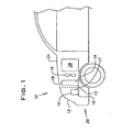
- FIG. 1 a vehicle 10 which includes a grille 12, an air conditioner condenser 14, a radiator 16 and a radiator fan 18.
- the air conditioner condenser 14 and radiator 16 are examples of devices present within vehicle 10 that contain heat exchange surfaces upon which is applied an ozone depleting substance.
- ozone depleting system means a system containing an "ozone depleting catalyst” or “catalyst coating” applied to a “heat exchange surface” (as hereinafter defined).
- ozone depleting catalyst or “catalyst coating” applied to a “heat exchange surface” (as hereinafter defined).
- catalyst coating and “ozone depleting catalyst” are used interchangeably and, in a general sense, mean any composition, material, compound and the like that removes ozone from a gas (containing ozone) including by way of non-limiting examples, catalyst compositions, adsorbent compositions, absorbent compositions, polymeric compositions and the like.
- ozone depleting catalyst or “catalyst coating” includes a composition, material, compound and the like that contains, at least as one of its elements, manganese in oxide form, such as, but not limited to, the various manganese compounds set forth below applied to or even comprising a heat exchange surface of a heat exchange device.
- the "catalyst coating” or “ozone depleting catalyst” terminology can include in its formulation the addition of signal enhancing or generating elements, as defined further below, even though such elements may make no contribution to the ozone depleting characteristics of the catalyst.
- the catalyst coating is assignee's catalytic material sold under assignee's brand name "PremAir"®.
- Heat exchange device is used in its customary broad sense to include devices which treat fluids, gases or liquids, by increasing or decreasing the temperature of an incoming stream.
- Heat exchange surface means a surface associated with a heat exchange device over which a gas stream containing ozone, typically atmospheric air, passes.
- the heat exchange surface is typically at an elevated temperature over ambient (i.e., about 90°C or higher) at which temperature the catalyst coating is catalytically effective to remove ozone, preferably by converting ozone to oxygen through the reaction of O 3 ⁇ 3/2 O 2 . It is to be appreciated that the conversion efficiency of the catalyst coating increases with increasing temperature so that a specific temperature at which the catalyst coating is effective to remove ozone cannot be stated.
- the catalyst coatings as set forth in detail below have conversion efficiencies of between about 50 to 100% at temperatures of about 25 to 200°C.
- the catalyst coating is applied as a coating to the heat exchange surface typically through dipping or spraying techniques.
- the catalyst is applied as a "high surface area" coating meaning that the surface area of the catalyst coating is at least about 100 m 2 /g and more preferably in the range of about 100 to 300 m 2 /g.
- the coating thickness is about that of paint, typically between about 10 to 30 ⁇ m with an average thickness of about 20 ⁇ m. It is important to note that the thickness of the ozone depleting substance cannot be of a magnitude which interferes with the air flow (pressure drop) and heat exchanging properties of the heat exchange surface to which it is applied.
- heat exchange surfaces are preferably surfaces typically located toward the front of the vehicle that catch air during vehicle motion and are in the vicinity of the cooling fan.
- Useful heat exchange surfaces include surfaces of the radiator and air conditioning condenser and the like which are all located and supported within the housing of the vehicle.
- heat exchange surfaces can include the face 13 and side 15 surfaces of air conditioning condenser 14 and face 17 and side 19 surfaces of radiator 16. These surfaces are located within the housing 24 of vehicle 10 and are typically under the hood of vehicle 10 between the front 26 of the vehicle and the engine 28.
- the heat exchange device is a radiator in a moving vehicle, typically, a brazed aluminum radiator as shown in Figures 2, 3 and 3A .
- a liquid coolant typically antifreeze
- the tubes are oriented to extend horizontally across the radiator face.
- a common construction is to have tubes 30 extend vertically. Tube orientation is not a limitation to the invention, but is a factor which is to be considered.
- a sheet of corrugated thin aluminum or aluminum foil Within the open space between adjacent tubes.
- a channel 33 is defined as the open space running from the front to the back face of the radiator between adjacent corrugations.
- the corrugated sheet will be referred to as a fin row 32 and each half corrugation within the fin row will be defined as a radiator fin 34, fins 34A, 34B, 34C, being designated in Figure 3 .
- Fin spacing is defined as corrugations per inch and the depth of the channel.
- the grooves or ridges 36 of the corrugations are brazed within channel 33 to tubes 30.
- the flux for brazing is typically a potassium/aluminum/fluoride substance (K Al F) commonly known by the brand name Nocolok (available from Omni Technologies Corp.) which is deposited over confronting tubular surfaces in channels 33 and covers the aluminum surface of tubes 30 and fins 34.
- each fin 34 extends the length of channel 33 as shown in Figure 3 and typically each fin 34 and channel length is about 0.5" to 2.0". Further, to enhance the cooling efficiency of fins 34, each fin is typically slotted at 35 to form louvers 37 as shown in Figure 3 and 3A . It is or should be appreciated that the catalyst coating applied to radiator fins 34 cannot block louvers 37 nor materially increase the gauge thickness of fins 34 to impact the air flow (pressure drop) or heat conductability of fins 34. Accordingly, for purposes of this invention, it is to be recognized that the catalyst coating thickness is to be kept at a minimum.
- the thickness of the coating and the heat exchange surface to which the catalyst coating is applied affects the adhesion characteristic of the coating and its ability to withstand motor vehicle vibrations to which the fins are inherently subjected.
- the formulations of the ozone depleting catalyst set forth below, have been found to exhibit excellent adhesion properties when applied directly to an aluminum or brazed aluminum surface as compared to other surfaces. Balancing, in a sense, the desired adhesion of the catalyst coating without adversely affecting the air flow and heat transfer characteristics of the radiator fins, it has been determined that catalyst coating thicknesses of about 10-30 ⁇ m (approximately 20 ⁇ m average) are acceptable for aluminum radiators.
- Other heat exchange surfaces may require the addition of a substrate coating on which the catalyst coating is applied or the catalyst coating formulation may change to provide an adhesive component to the catalyst.
- the efficiency of the ozone depleting system discussed above can be directly measured by sensing the ozone concentration in atmospheric air upstream and downstream of the heat exchange surface coated with the ozone depleting catalyst. In fact, such measurements are used to obtain the test data upon which the invention of this patent is based and to certify the catalyst coated radiator as an ozone depleting system.
- an ozone detector having a sensitivity to distinguish variations in ozone concentrations down to 1 to 10 parts per billion. This results because of ozone variation within the atmosphere. Most often the ozone concentration may be in the range of 100 to 200 ppb.
- a sensing system thus has to have a sensitivity of at least 10 ppb to determine if a failure in the ozone depleting system has occurred.
- laboratory and even hand held field ozone detectors possess this sensitivity, but they are not practical for installation and use in a moving vehicle.
- the efficiency of the ozone depleting substance to decompose ozone to oxygen in the motor vehicle application of the invention depends on several factors, including i) the concentration of ozone in atmospheric air, ii) the accessibility of the ozone to active sites on the surface of the catalytic material, iii) the operating temperature that controls catalytic activity of the ozone deleting catalyst and iv) the amount of atmospheric air that passes over the catalyst coated on the radiator surface. (That is the air flow rate is related to contact time of an ozone molecule with the active sites on a catalyst's surface.)
- the physical and chemical properties of the catalyst and engineering design considerations of the coated radiator are also important considerations that affect decomposition efficiency.
- the principal factor which has been found to affect the conversion efficiency of the catalyst coating is external matter, referred to as airborne particulate matter, to which the radiator is exposed. It is possible for such external matter to be deposited on the active sites of the catalyst and block the catalyst sites, physically or chemically. Physically, it is potentially possible to simply block the sites so that atmospheric air can not catalytically react with the active sites. Chemically, it is potentially possible to chemically poison the sites by introducing new compounds or altering the catalyst surface structure.
- the OBD system of the present invention may provide an interlock which can be keyed to a moisture sensor or to the actuation of the vehicle's windshield wipers to simply deactivate the system during the time the vehicle is operating in the rain or when the air is at excessively high moisture levels. Stones and foreign objects impact the radiator during vehicle operation resulting in localized damage to any fin row and obviously the catalyst coating on the fin row in that localized area. However, the coating on the remainder of the radiator is not affected and the system is still operative to remove ozone from atmospheric air. Because of the tight fin row spacing it is not possible for a person to inadvertently wipe away any significant amount of the catalyst coating on a "system" basis while servicing or attending the radiator.
- the catalyst surface can contain deposits of ambient airborne particulates less than 10 ⁇ m in size ( ⁇ PM 10 ) and contaminant phases foreign road matter, principally in the form of salts (carbonates, nitrates, sulfates, chlorides) which contain elements such as C, N, O, Na, Mg, Al, Si, S, K and Ca.
- contaminant deposits i.e., ambient ⁇ PM 10 and contaminant deposits, has not been observed to prevent the catalytic coating from operating to remove ozone although at reduced conversion efficiencies.
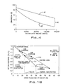
- FIG. 4 is an actual plot of the ozone conversion efficiency of a number of radiators treated witch a variety of various catalyst coatings for vehicles driven the miles shown on the x-axis.
- the conversion efficiency is shown as a band designated by reference numeral 40 extending between an upper trace 41 and a lower trace 42 because several different formulations of catalysts forming the catalyst coating were investigated. Any particular formulation of catalyst coating would be depicted by a curve falling within band 40.
- Band 40 shows that the efficiency of the ozone depleting substance, no matter what its composition, drops as the catalyst ages but the catalyst coating still remains effective in depleting ozone, although at a reduced efficiency.
- the ozone depletion system can only cease to remove ozone from atmospheric air only when the catalyst coating is no longer present on the radiator. It is to be appreciated that the catalyst coating is exposed, over time, to large volumetric flows of atmospheric air containing any number of particulates which strike the thin catalyst coating and can physically erode, ablate or spall the catalyst coating. Complete wearing away of the catalyst coating during on-road aging has never been observed.
- FIG. 6A A microscopic portrayal of the wear is schematically represented in Figures 6A, 6B and 6C .
- the MnO 2 particles in the catalyst coating are shown freshly applied to aluminum fin 34 (coated with K-Al-F brazing flux).
- the MnO 2 particles designated by reference numeral 55 are somewhat spherical with diameters or thicknesses of anywhere between about 0.1 to 25 ⁇ m.
- the MnO 2 particles are literally packed until reaching desired catalyst coating thickness, i.e., an average of 20 ⁇ m, shown by reference dimension "A".
- Figure 6B depicts the homogenous thinning of the catalyst coating discussed with reference to Figure 5B .
- the homogeneous thinning may simply result in a removal of MnO 2 particles or reduction in MnO 2 particle size or a combination thereof shown by reference dimension "A'".
- Figure 6C illustrates the heterogeneous wear discussed with reference to catalyst coating 50.
- the exposed fin row or tube area designated by reference numeral 56 results in an efficiency loss which eventually increases to the point where the catalyst coating is removed resulting in a nonfunctional ozone depletion system.
- Proposed emission regulations extend a credit for an ozone depleting system so long as an on board detector can sense whether the system is functioning at any efficiency to reduce ozone.
- Figure 4 shows that wear resulting from normal contaminant deposits cannot prevent the ozone depletion system from functioning at some efficiency level to deplete ozone.
- the ozone depletion system ceases to function only when the catalyst coating has been removed to an extent that the catalyst coating is for all intent and purposes eliminated. This can occur, although rarely, when the catalyst coating physically wears away as explained in the discussion of Figures 5 and 6 .
- an OBD detector is constructed as described below which measures the presence or absence of the catalyst coating by detecting a physical characteristic as property of the catalyst coating. If the catalyst coating property or characteristic is not detected, the ozone depletion system is no longer functional and a warning is triggered to the operator.
- Contemplated emission regulations also propose a greater emission "credit" if the OBD detector can ascertain when the efficiency of the ozone depletion system has been reduced to a set level.
- This set level of efficiency reduction is defined herein as a "threshold failure".
- the threshold failure can be defined to occur at any reduced ozone conversion percentage, i.e., 60%, 50%, 40%, 30%, etc.
- the catalyst coating will be assumed to have an ozone depletion efficiency of 80% when fresh and a normal deactivation is defined to occur when the ozone depletion efficiency drops to 50%.
- a catalyst coating (one of the formulations making up band 40 in Figure 4 ) which will not drop in efficiency less than 50% because of degradation from contaminant deposits. Threshold failure occurs then only if some portion of the catalyst coating wears away (i.e., Figures 5 and 6 ). It is important to recognize that a threshold failure can theoretically occur by wear of a fresh catalyst coating before or during the time the catalyst coating ages with contaminant deposits as well as wear of an aged catalyst coating that has somewhat stabilized in its ability to deplete ozone attributed to contaminant deposits.
- this invention measures a physical characteristic of the catalyst coating to determine when the ozone depletion efficiency of the catalyst coating drops below the threshold failure level which is defined as approximately 50% or more of the certified ozone depletion efficiency (for specific vehicles) after long term mileage accumulation.
- This invention in its broad sense, constructs an OBD detector to detect a catalyst coating physical characteristic or attribute to indirectly determine whether the catalyst coating ceases to function to remove ozone because of the absence of the catalyst coating.
- this invention constructs an OBD detector that measures a physical characteristic or attribute of the catalyst coating in place of a direct ozone measurement to determine if the efficiency of the ozone depleting system has dropped to a threshold failure.
- this invention constructs an OBD detector which senses and measures a physical characteristic or attribute of the catalyst coating to determine in the first instance, if a threshold failure has occurred and in the second instance, provide a clear demarcation when the ozone depletion system is nonfunctional.
- the actual OBD ozone conversion sensor employed to sense or measure a distinguishing physical characteristic or attribute of the catalyst coating can take the form of a) an electrical sensor, b) a magnetic sensor, c) an optical sensor or d) a thermal sensor.
- this invention recognizes that contaminant deposits will cause an ozone efficiency conversion drop of the catalyst coating to some set percentage; that any further decrease in efficiency conversion results from an abnormal wear pattern; that the wear pattern can be defined as heterogenous or homogenous or a combination thereof; that there are specific characteristics of the MnO 2 catalyst in the catalyst coating and that those specific characteristics can be detected, notwithstanding the presence of contaminant deposits, to detect the abnormal wear pattern and determine the catalyst functionality.
- the MnO 2 catalyst has been found to provide measurable distinctions (i.e., a brown/black color for the optical sensor and specific electrical conductivity characteristic for the electrical sensor) which are sufficient or which can be enhanced by the presence of markers (as defined later) or even generated by markers.
- Those sensors are particularly suited for OBD application because their sensitivity is satisfactory and they are robust and inexpensive. While the sensors can detect the normal threshold whereat the catalyst coating efficiency drops to some threshold, and thus determine if the abnormal wear occurs, importantly the sensors can also determine the presence or absence of the catalyst coating to determine if the system is functioning or not.
- the invention in another sense, is the correlation resulting from the characteristics of the catalyst coating to asymptotically approach, with mileage accumulation, a set conversion efficiency threshold with a deviation therefrom attributed to catalyst wear which catalyst behavior and wear is attributed to a characteristic of the catalyst coating that can be physically sensed.
- any type of sensor can be used to physically sense the catalyst characteristic which indirectly establishes the efficiency of the catalyst system. i.e., a chemical response reaction (efficiency) is correlated to a sensed physical property.
- the sensors mentioned in part B(2) are passive sensors in that the measurements are taken while the catalyst coating is normally functioning and without any interference in the normal aging and/or reaction function of the catalyst coating. Passive sensors form the preferred embodiment of this invention.
- the MnO 2 catalyst in the catalyst coating has a somewhat distinguishing property of a limiting efficiency threshold independent of mileage accumulation when used in the vehicular environment described in detail herein.
- the methodology is believed applicable to other catalysts exhibiting similar behavior.
- catalysts other than MnO 2 ) which are used in an environment whereat the catalyst will not normally or even abnormally experience a catalyst failure through chemical poisoning of the catalyst and in which the catalyst is exposed to a contract stream producing a catalyst reaction that, with aging, diminishes to some generally constant or steady state efficiency reaction (and not zero). Catalyst failure, functional or efficiency, can therefore be determined by abnormal wear of the catalyst in the coating resulting in coating loss.
- the MnO 2 catalyst in catalyst coating 50 ( Figure 6A ) has a high electrical resistance and a low electrical conductivity but is electrically conductive. Accordingly, an electrical circuit can be constructed which must physically pass through a portion of the catalyst coating to complete the circuit. Should catalyst coating 50 wear away, the circuit is open and electron flow ceases. Alternatively, a circuit can be constructed which passes through the electrically conductive radiator when the catalyst coating wears away. By measuring an electrical characteristic of the circuit-current, resistance and/or voltage - preferably voltage because of the low electrical conductivity of MnO 2 , the absence of the MnO 2 catalyst can be detected.
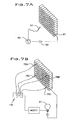
- Electrical circuit as shown comprises a power supply 60, i.e., a DC power supply in the form of a battery, with one of the terminals 61 of battery 60 (negative) connected to an uncoated portion of radiator 16 and with the other terminal of battery 60 (positive) connected to a probe 62 with a multimeter 64 inserted into the circuit for measurements.
- a power supply 60 i.e., a DC power supply in the form of a battery
- a probe 62 with a multimeter 64 inserted into the circuit for measurements.
- a probe 62 By contacting probe 62 at any coated fin (or tube) a closed circuit is established.
- Voltage readings measured by multimeter 64 for seven different fins with a fresh, unaged catalyst coating and with an aged catalyst coating is set forth in table 1 below. Table 1 datum was generated with a 9 volt power supply.
- Tables one and two demonstrate that an electrical circuit passing through a portion of the catalyst coating can be established as a closed circuit with different electrical characteristics when the catalyst coating is fresh as compared to the catalyst coating when aged.
- Any number of electrical circuits can be constructed and the invention in its broadest sense encompasses all such circuits known to those skilled in the art.
- probe 62 in Figure 7 can be replaced with a spring bias contact which establishes electrical contact with the underlying aluminum fin row or tube if the catalyst coating wears away. In such event, a nonfunctioning ozone depletion system results and a significant increase in voltage would be observed.
- the electrical circuit be a circuit that opens when the catalyst coating wears away. As the catalyst coating wears (assuming a homogenous wear pattern as discussed with reference to Figures 5B and 6B ), electron conductivity through the catalyst coating decreases and the decrease can be sensed to determine a catastrophic failure or a threshold failure.
- Such a circuit can be readily constructed by imbedding an exposed lead from the power supply underneath the catalyst coating providing that the lead does not electrically contact the aluminum radiator, i.e, electrically isolated.
- Two ways that this can be accomplished in an inexpensive manner are illustrated in Figures 8A and 8B .
- Figures 8A and 8B that portion of the electrical lead connected to the power supply as shown with its insulation removed for drawing clarity so that only its electrical conductor 70 (typically an aluminum wire) is shown.
- that portion of the electrical lead which extends underneath the catalyst coating is shown as an exposed section designated by reference numeral 71 and is characterized by having its insulation covering over the top portion of electrical conductor 70 removed so that only a bottom insulation portion 72 extends about the bottom portion of electrical conductor 70.
- Exposed portion 71 can extend the length of channel 33 ( Figure 3 ) or only a portion of the channel length. It is to be appreciated that electrical conductor 70 establishes a line contact in the electrically isolated exposed lead embodiment of Figure 8A . Because the electrical OBD sensor is preferred to measure a homogenous catalyst coating wear pattern, it may be desirable to sense the catalyst coating wear over a coating area.
- the insulation over the exposed portion of lead conductor 70 is stripped away and the bottom portion of electrical conductor 70 is glued to an insulating strip 74 which basically comprises the same type of insulation as originally shielding electrical conductor 70, i.e., any known ceramic or plastic or rubber insulation.
- the exposed section 71 of lead 70 resembles the exposed section 71 of the lead shown in Figure 8A except that the underlying insulation shown as 72 in Figure 8A is in the form of an insulation strip 74.
- a conductive strip 75 Over the exposed portion of electrical conductor 70 is a conductive strip 75 shaped similar to insulation strip 74.
- Conductive strip 75 is preferably of the same material as electrical conductor 70, i.e., aluminum.
- the sandwich construction of Figure 8B is assembled and held in place by an appropriate adhesive able to withstand the operating temperatures of the radiator environment.
- the exposed wire embodiment of Figure 8A is ideally suited for application to ridge or groove 36 of the fin row corrugation as shown in Figure 9A . This is a preferred position for sensing catalyst coating wear occurring at the apex 77 of the catalyst coating. As the apex of the catalyst coating wears, electrical conductivity will diminish until the catalyst coating wears away from exposed portion 71 at which point an open circuit will occur.
- the electrically isolated strip embodiment illustrated in Figure 8B is preferably suited for application to radiator tube 30 as shown in Figure 9B or to a single radiator fin 34 as shown in Figure 9C . It is, of course, appreciated that the electrically isolated wire embodiment of Figure 8A can also be applied to the radiator tube and fin row illustrated in Figures 9B and 9C .
- FIG. 10A, 10B and 10C there is shown various arrangements for mounting the electrically isolated wire embodiment of Figure 8A in radiator channel 33.
- an exposed isolated wire section 71 extends within a channel 33 and an electrical characteristic of the circuit, current or voltage, is sensed to determine wear of the catalyst coating.
- Table 3 below sets forth voltage and current measurements for Figure 10A .
- TABLE 3 Voltage v* Current ⁇ a Thick Catalyst Coating (-40 ⁇ m) 2.6 0.85 Thin Catalyst Coating (-20 ⁇ m) 1.5 0.19 Very Thin Catalyst Coating (-10 ⁇ m) 0.66 0.072 * Input voltage was 5.0 volts.
- Figure 10B illustrates the inclusion of several isolated, exposed wire sensors within a single channel having various lengths of exposed sections 71. This arrangement essentially places the isolated wires in series so that an average value indicative of the deterioration state of the channel is obtained. Alternatively, each of the exposed, isolated wire sections 71A, 71B, 71C can be sequentially switched into and out of the circuit as by switch 79.
- Figures 11A, 11B and 11C A similar arrangement is disclosed in Figures 11A, 11B and 11C for the electrically isolated strip embodiment of Figure 8B .
- Figure 11B shows a plurality of isolated strip sections 75A, 75B and 75C in different channels 32A, 32B, 32C, respectively, with the strip channels connected in parallel within the electrical circuit shown.
- Figure 11C shows that the channels can be switched into and out of the circuit for specific channel measurements. Parallel connection allows summing of the currents to give an average value more indicative of the overall functioning of the ozone depletion system because of the placement of the exposed isolated strip sections at strategic positions within radiator 16. It is also possible to similarly position a plurality of the isolated wire sections illustrated in Figures 10A-10C at a plurality of positions within the radiator and connect those sensors in parallel within the circuit.
- any number of circuits may be constructed.
- preferred form of an OBD ozone depletion sensing circuit would preferably utilize a MOSFET (metal-oxide semi-conductor field effect transistor) to detect and switch a voltage sufficient to activate a warning light in the cab of a vehicle when the ozone depletion system is determined to have experienced a catastrophic failure or has been determined to simply no longer function.
- MOSFET metal-oxide semi-conductor field effect transistor
- the MOSFET can function as a voltage-controlled gate that opens when the gate voltage is above a threshold which, in turn, can light bulb 82. More particularly, an adjustable gate resistance tuner 83 can be set to match a known coating resistance threshold (nonfunctional or threshold failure) at which a failure occurs to produce a gate voltage sufficient to switch the transistor to actuate bulb 82 in accordance with the following general equation.
- V gate V B ⁇ R gate ⁇ I R gate + R coat
- V gate minimum voltage required to turn on bulb 82
- V B battery output R gate is set at threshold
- R coat is the resistance of the catalyst coating as detected by the circuits of Figures 10 and 11 and inputted at 84
- Figure 7B diagrammatically shows the implementation of the Mosfet circuit illustrated in Figure 12 in the conductive strip parallel circuit illustrated in Figure 11B (or the circuit illustrated in Figure 11C ).
- conductive strips 75A, 75B, 75C, and 75D are strategically positioned at the corners of radiator 16 although other locations can be utilized i.e., corresponding to certification measurements.
- the sensor positions shown in Figure 7B can be utilized by the optical sensors described in Section D hereof.
- the preferred embodiment is to use the electrical OBD sensor at ambient temperature just as the vehicle is started, or as indicated in the preceeding discussion, a switch (not shown in Figure 12 ) is provided in the electrical OBD circuit which will not activate the OBD ozone depletion detector system until the vehicle has reached normal operating temperature.
- a switch (not shown in Figure 12 ) is provided in the electrical OBD circuit which will not activate the OBD ozone depletion detector system until the vehicle has reached normal operating temperature.
- an increase in temperature can remove moisture trapped at ambient temperature (which increases the resistance) from the pores of the HSA MnO 2 catalyst resulting in a resistance differential that can uniquely identify the coating and determine its presence on a radiator.
- a temperature look-up table has to be provided in the vehicle's ECU (engine control unit) and a corresponding adjustment made to gate resistor 83 which is not preferred.
- the switch may also be actuated by a moisture sensor present in the vehicle to prevent OBD sensing when the vehicle is driven in the rain and the catalyst coating is wet.
- a plurality of electrical sensors are preferably placed at strategic locations in the radiator corresponding to the positions where ozone measurements are taken when the ozone depletion system is certified as discussed above.
- a tag or tracer can be added to the catalyst coating formulation to increase the electrical conductivity of the catalyst coating such as but not limited to metals known to be electrically conductive and magnetic materials.
- MnO 2 catalyst exhibits a high resistance
- the tabular values show a decrease in the electrical signals as the catalyst coating ages.
- Contaminants such as salts deposited on the catalyst coating during normal use are believed to contribute to the change of electrical conductivity detected by the electrical sensor discussed in Figures 8A and 8B . It is possible that a correlation exists between salt deposits and conversion efficiency of the catalyst coating at least up to a threshold failure as detected by the electrical sensor.
- light or other forms of electromagnetic radiation can be absorbed or emitted by the catalyst coating and detection of the absence or presence of reflected or emitted radiation utilized to determine degradation or wear of the catalyst coating and hence the efficiency of the ozone depletion system and in the second instance the absence or presence of the catalyst coating on the radiator itself to determine if the ozone depletion system has ceased to function.
- the aluminum heat exchange surface which is a silver colored metallic reflective surface is exposed (as contrasted to the catalyst coating which is a black oxide absorptive surface) producing easily distinguishable light signals to indicate a nonfunctional ozone depletion system.
- the optical OBD ozone depletion sensor directs light against the catalyst coating and senses the incident light to determine in the first instance whether the catalyst coating is functioning at least at some set efficiency and/or in the second instance whether the catalyst coating is present or absent from the radiator surface exposed to the light.
- the light may be radiation at any frequency and may be coherent (same wavelength in phase) or collimated or focused or diffused or polarized and may be generated from light sources such as incandescent light bulbs, light emitting diodes (LED), lasers, strobes or other pulsed or modulated light sources. Detection of the incident light may be by inexpensive photodiodes, solar cells or photo resistors.
- Transmission can in theory be direct as shown in Figure 14A in which a light source 90 directs coherent light through radiation channels 32 for detection by a light detector 92 on the opposite side. Only the light not striking the coated catalyst passes through the channel so that an increase in light intensity indicates reflection of light striking uncoated radiator surface when passing through the channel. In practice, reproducible signals have not been observed using laser light sources at various visible or near IR wavelengths.
- the light source is offset at an angle to the channel and the light is collimated to strike the channel at an angle, referred to herein as "indirect transmission"
- the light is totally absorbed by the catalyst coating and detector 92 does not normally detect the transmitted light if the catalyst coating is present.
- the use of lasers, collimator, lenses, mirrors, polarizers and/or filters increase the cost of the optical sensor.
- a system which senses the refection of diffused light from any conventional source as shown in Figures 14C and 14D may be utilized.
- the light is directed in a diffused manner against the face of the channels and any light reflected is sensed by a detector on the same side of the radiator as the light source.
- a number of channels covering a radiator surface area can be analyzed by sensing reflected light.
- the light source is directed at an angle to the channel length to assure that some portion of the light is reflected in the direction of detector 92. This arrangement is referred to herein as "forward diffuse reflection".
- an opaque partition 93 with a slit 94 adjacent the radiation channel face must be provided.
- partition 93 To avoid the use of partition 93 it has been determined that if the light source is simply aligned with the channel, the natural diffusion of the light is sufficient to provide sufficient reflected radiation when the catalyst coating is not present to be detected by detector 92.
- This arrangement is referred to herein as "backward diffuse reflection".
- light source 92 can be placed slightly behind or aligned with detector 92 and represents a preferred embodiment of the invention.
- the orientation of the fin in the channel has an effect on the radiation detected by the detector in the reflection embodiment of the invention.
- radiator 16 was described as having horizontal tubes 30. If the radiator has vertical tubes the orientation of the light source and detector may have to change (from that used in the horizontal tube arrangement) and the set detector ranges may be different.
- the MnO 2 catalyst coating is porous and a brown/black color which absorbs electromagnetic radiation extending from the ultra-violet through the infra-red (IR) wavelength regions.
- the underlying silver colored aluminum fin row or tube (more specifically the underlying K-Al-fluoride brazing flux deposited on the aluminum surface) does not significantly absorb radiation at those wavelengths and reflects the radiation.
- coherent visible red light (wavelength of 0.65 to 0.70 ⁇ m) in an indirect transmission arrangement ( Figure 14B ) exhibits excellent absorption characteristics by the catalyst coating.
- red light exhibits excellent absorption characteristics in black paint.
- the MnO 2 catalyst coating can be readily differentiated from brazed aluminum flux by radiation in this specific absorption band.
- cost effective detectors are not available to detect radiation at that wavelength.
- Cost effective detectors can detect radiation in the near infrared region, i.e., wavelengths of approximately 0.8-2.5 ⁇ m.
- the MnO 2 catalyst coating is easily differentiable from brazed aluminum flux with light in this region (0.8-2.5 ⁇ m).
- a “marker” may be applied by seeding or doping the catalyst coating or, alternatively, tagging the brazed aluminum flux surface with an organic or inorganic material that can withstand radiator operating temperatures to enhance the near IR signal.
- the marker is a strong absorber of radiation in the red visible to the near-infrared to the low end of the mid-infrared region defined herein as wavelengths of 0.65-5 ⁇ m with a peak wavelength of 1 ⁇ m which will hereinafter be referred to as "near IR”.
- Near IR a strong absorber of radiation in the red visible to the near-infrared to the low end of the mid-infrared region defined herein as wavelengths of 0.65-5 ⁇ m with a peak wavelength of 1 ⁇ m which will hereinafter be referred to as "near IR”.
- the light is selected as visible light extending to the near infra-red region;
- the light source is preferably an LED (light emitting diode) generating diffused light;
- the sensor is an inexpensive photodiode and the components are placed in a backward diffuse reflection arrangement.
- the general arrangement is pictorially represented in Figure 13 . Essentially, a power supply 95 actuates a LED 96 and a photodiode 97 senses reflected radiation which at a set intensity level actuates a warning light 98 to the operator in the vehicle's cab.
- LED 96 is preferably pulsed or modulated by a clock circuit (not shown) to provide a signature or fingerprint light signal permitting photodiode 93 to distinguish background radiation.
- the photodiode signal may be amplified to boost sensitivity arid the diode signal transmitted through a band pass filter (i.e., low and high to detect an threshold failure limit and a nonfunctional limit) (not shown) or a comparator (not shown) to ascertain the occurrence of a failure at a set photodiode voltage.
- Photodiode voltage signals using back diffuse reflection arrangement with radiator tubes 30 horizontal (A) and radiator tubes 30 oriented vertical (B) for radiators with and without a catalyst coating is set forth below in table 5.
- the light wavelength used to illuminate the radiator was in the near IR region.
- TABLE 5 PHOTODIODE DETECTOR VOLTAGE (Near IR LED Source) COATED WITH MnO 2 (A) (B) Fresh 0.3 0.4 Aged-Front Radiator Face 0.5 0.7 Aged-Back Radiator Face 0.4 0.5 UNCOATED Fresh 1.8 1.8 Aged-Front Radiator Face 0.7 0.9 Aged-Back Radiator Face 1.1 1.2
- the data shows that when the catalyst coating is not present, a significant difference in photodiode signals occur.
- the data also shows that there is little difference in the optical signal for a fresh and aged sample. This is somewhat consistent with expected wear results since catalyst coating was fully present on the aged radiator tested. Note that the photodiode signal is less for the aged uncoated radiator than for a fresh uncoated radiator. The difference is attributed to contaminant deposits accumulation.
- Photodiode responses were obtained for LEDs emitting various color (wavelengths) lights on coated and uncoated radiators and also on a plain strip of aluminum foil. Data is shown in table 6 below based on forward reflection measurements ( Figure 14C ). TABLE 6 Radiation Photodiode Detector Voltages for Different Light Sources on Different Surfaces Uncoated Foil Coated Foil Painted Foil Uncoated Radiator Coated Radiator Near IR 7.3 0.72 1.4 3.7 0.20 White 2.3 0.15 0.14 0.72 0.09 Red 7.1 0.27 0.24 1.6 0.15 Yellow 2.1 0.04 0.05 0.29 0.03 Blue 0.37 0.008 0.01 0.06 0.003
- the invention contemplates the addition of a marker which either i) makes the catalyst coating or the underlying substrate (radiator) reflective or absorptive of radiation at a set wavelength or ii) enhances the absorption or reflective signal of the catalyst coating or underlying substrate (radiator).
- Markers can take the form of seeds or tags physically within (doped) and formulated as part of the catalyst coating or be an absorptive or reflective strip placed between the substrate (radiator) and the catalyst coating or, conceptually, on top of the catalyst coating.
- Tags can take the form of powders, suspensions or solutions including light emitting phosphors, flourescent materials, inks, dyes and paint.
- Particles should typically be of a size about 0.3 ⁇ m and preferably not greater than about 1.0 ⁇ m.
- the strip although a marker, is not a measurement of the activity of the catalyst coating but is a measure of whether the catalyst coating is or is not present and can detect or better detect a heterogeneous wear pattern as discussed above. In all instances, the marker provides a signature or fingerprint signal to the light detector.
- a marker can be used to emit radiation when the catalyst coating is heated at a slightly elevated temperature at which the radiator is subjected, i.e., approximately 50°C.
- the emissions marker can take the form of a thermochromic material emitting (absorbing) radiation at set wavelengths such as black or blue at room temperature and bright red, pink or colorless at elevated temperatures.
- light phosphors or silicon powder which has a band gap of 1.17 EV and starts to absorb at 1.2 ⁇ m or liquid crystals can be used as tags, all of which are preferably not greater than about 1.0 ⁇ m when used as tags. This is in the near-IR region and can be used to detect the catalyst coating either by absorption (i.e., the near IR signals noted above) or emission.
- a possible marker material that is commercially used to make infrared detector strips contains a patch that absorbs the near-IR radiation given off by LEDs and laser sources.
- Such commercial near-IR strip is available from Tandy Corporation (infrared sensor, CAT. No. 276-1099) and absorbs near-IR radiation between 0.7 and 1.3 ⁇ m with a maximum at 1.0 ⁇ m.
- the material comprising the strip can be added to the MnO 2 catalyst coating formulation as a tag or seed or used in strip form. Emission radiation must use differentiation circuitry to distinguish background noise resulting from other surfaces inherently emitting radiation at elevated temperature.
- Test data in table 7 below take in a forward reflective arrangement shows that a thermochromic phosphor emits or fails to emit a reflective signal when a red or near IR light emitting diode is used to illuminate the radiator at ambient or operating temperatures.
- TABLE 7 Photodiode Detector Voltage (Red LED Source) Photodiode Detector Voltage (Near IR LED Source) 24°C 75°C* 24°C 75°C* AMBIENT ROOM LIGHT 0.21 0.22 0.27 0.27 UNCOATED RADIATOR 3.6 3.4 1.8 1.8 HSA MNO2 COATED RAD.
- this invention includes the optional positioning of an optical sensor on the front face and an optical sensor on the back face of the radiator (generally longitudinally aligned with one another to preferentially sense the same radiator areas as the front and rear face) to monitor the differential effects of coating loss and/or contaminant deposition.
- the present invention includes any compositions which can remove ozone from a gas containing the same.
- Such compositions include ozone catalyzing compositions, adsorbing compositions, absorbing compositions and the like.
- ozone catalyzing compositions which contain manganese dioxide as explained in detail below.
- Ozone catalyzing compositions for use in the present invention comprise manganese compounds including manganese dioxide, non stoichiometric manganese dioxide (e.g., XMnO (1.5-2,01) ), and/or XMn 2 0 3 wherein X is a metal ion, preferably an alkali metal or alkaline earth metal (e.g. sodium, potassium and barium). Variable amounts of water (H 2 0, OH - ) can be incorporated in the structure as well.
- Preferred manganese dioxides, which are nominally referred to as Mn0 2 have a chemical formula wherein the molar ratio of oxygen to manganese is about from 1.5 to 2.0.
- manganese dioxide Mn0 2 can be used in catalyst compositions to treat ozone.
- Alternative compositions which are available comprise manganese dioxide and compounds such as copper oxide alone or copper oxide and alumina. Copper, however, is not preferred for an aluminum substrate.
- Useful and preferred manganese dioxides are alpha-manganese dioxides nominally having a molar ratio of oxygen to manganese of from 1 to 2.
- Useful alpha manganese dioxides are disclosed in U.S. Patent No. 5,340,562 to O'Young, et al.
- the preferred alpha-manganese dioxide is selected from hollandite (BaMn 8 0 16 .xH 2 0) cryptomelane (KMn 8 01 6 .xH20), manjiroite (NaMn 8 0 16 .xH 2 0) or coronadite (PbMn 8 0 16 .xH 2 0).
- Other transition metal ions may be substituted with the alpha-manganese dioxide structure such as Fe, Co, Ni, Cu, Zn and Ag.
- the manganese dioxides useful in the present invention has a surface area of at least 100 m 2 /g. Those materials are referred to as high surface area (HSA) Mn0 2 .
- the composition preferably comprises polymeric binders.
- the composition can further comprise precious metal components or metals, including platinum group metals and oxides of palladium or platinum also referred to as palladium black or platinum black.
- the amount of palladium or platinum black can range from about 0 to 25%, with useful amounts being in ranges of from about 1 to 25 and from about 5 to 15% by weight based on the weight of the manganese component and the precious metal component.
- compositions comprising the cryptomelane form of alpha manganese oxide, which also contain'a polymeric binder can result in greater than 50%, preferably greater than 60% and typically from 75-85% conversion of ozone in a concentration range of up to 400 parts per billion (ppb).
- the preferred cryptomelane can be made in accordance with methods described and incorporated into United States Patent Application Serial No. 08/589,182 filed January 19, 1996 (Attorney Docket No. 3777C), which is a priority application claimed by WO 97/11769 .
- the cryptomelane can be made by reacting a manganese salt including salts selected from the group consisting MnCl 2 , Mn(N0 3 ) 2 , MnSO 4 , and Mn (CH 3 COO) 2 with a permanganate compound.
- Cryptomelane is made using potassium permanganate; hollandite is made using barium permanganate; coronadite is made using lead permanganate; and manjiroite is made using sodium permanganate.
- alpha-manganese dioxide useful in the present invention can contain one or more of hollandite, cryptomelane, manjiroite or coronadite compounds. Even when making cryptomelane minor amounts of other metal ions such as sodium may be present. Useful methods to form the alpha-manganese dioxide are described in the above references.
- the preferred alpha-manganese dioxide for use in accordance with the present invention is cryptomelane.
- the preferred cryptomelane is "clean" or substantially free of inorganic anions, particularly on the surface. Such anions could include chlorides, sulfates and nitrates which are introduced during the method to form cryptomelane.
- An alternate method to make the clean cryptomelane is to react a manganese carboxylate, preferably manganese acetate, with potassium permanganate.
- the carboxylates are burned off during the calcination process.
- inorganic anions remain on the surface even during calcination.
- the inorganic anions such as sulfates can be washed away with the aqueous solution or a slightly acidic aqueous solution.
- the alpha manganese dioxide is a "clean" alpha manganese dioxide.
- the cryptomelane can be washed at from about 60°C to 100°C for about one-half hour to remove a significant amount of sulfate anions.
- the nitrate anions may be removed in a similar manner.
- the "clean" alpha manganese dioxide is characterized as having an IR spectrum as disclosed in United States Patent Application Serial No. 08/589,182 filed January 19, 1996 .
- a preferred method of making cryptomelane useful in the present invention comprises mixing an aqueous acidic manganese salt solution with a potassium permanganate solution.
- the acidic manganese salt solution preferably has a pH of from 0.5 to 3.0 and can be made acidic using any common acid, preferably acetic acid at a concentration of from 0.5 to 5.0 normal and more preferably from 1.0 to 2.0 normal.
- the mixture forms a slurry which is stirred at a temperature range of from about 50°C to 110°C.
- the slurry is filtered and the filtrate is dried at a temperature range of from about 75°C to 200°C.
- the resulting cryptomelane crystals have a surface area of typically in the range of at least 100 m 2 /g.
- ozone catalyzing compositions to remove ozone can comprise a manganese dioxide component and precious metal components such as platinum group metal components. While both components are catalytically active, the manganese dioxide can also support the precious metal component.
- the platinum group metal component preferably is a palladium and/or platinum component.
- the amount of platinum group metal compound preferably ranges from about 0.1 to about 10 weight percent (based on the weight of the platinum group metal) of the composition.
- platinum is present it is in amounts of from about 0.1 to 5 weight percent, with useful and preferred amounts of the catalyst composition volume, based on the volume of the supporting article, ranging from about 17.6 to about 2472.0 g/m 3 (about 0.5 to about 70 g/ft 3 ).
- the amount of palladium component preferably ranges from about 2 to about 10 weight percent of the composition, with useful and preferred amounts on the catalyst composition volume ranging from about 353.1 to about 8828.6 g/m 3 (about 10 to about 250 g/ft 3 ).
- compositions can comprise a suitable support material such as a refractory oxide support.
- a suitable support material such as a refractory oxide support.
- the preferred refractory oxide can be selected from the group consisting of silica, alumina, titania, ceria, zirconia and chromia, and mixtures thereof.
- the support is at least one activated, high surface area compound selected from the group consisting of alumina, silica, titania, silica-alumina, silica zirconia, alumina silicates, alumina zirconia, alumina-chromia and alumina-ceria.
- the refractory oxide can be in suitable form including bulk particulate form typically having particle sizes ranging from about 0.1 to about 100 and preferably 1 to 10 ⁇ m or in sol form also having a particle size ranging from about 1 to about 50 and preferably about 1 to about 10 ⁇ m.
- a useful titania sol support comprises titania having a particle size ranging from about 1 to about 10, and typically from about 2 to 10 ⁇ m.
- a coprecipitate of a manganese oxide and zirconia is also useful as a preferred support.
- This composition can be made as recited in U.S. Patent No. 5,283,041 .
- this coprecipitated support material preferably comprises in a ratio based on the weight of manganese and zirconium metals from 5:95 to 95:5; preferably 10:90 to 75:25; more preferably 10:90 to 50:50; and most preferably from 15:85 to 50:50.
- a useful and preferred embodiment comprises a Mn:Zr weight ratio of 20:80.
- U.S. Patent No. 5,283,041 describes a preferred method to make a coprecipitate of a manganese oxide component and a zirconia component.
- a zirconia oxide and manganese oxide material may be prepared by mixing aqueous solutions of suitable zirconium oxide precursors such as zirconium oxynitrate, zirconium acetate, zirconium oxychloride, or zirconium oxysulfate and a suitable manganese oxide precursor such as manganese nitrate, manganese acetate, manganese dichloride or manganese dibromide, adding a sufficient amount of a base such as ammonium hydroxide to obtain a pH of 8-9, filtering the resulting precipitate, washing with water, and drying at 450-500°C.
- suitable zirconium oxide precursors such as zirconium oxynitrate, zirconium acetate, zirconium oxychloride, or zirconium oxysulfate
- a suitable manganese oxide precursor such as manganese nitrate, manganese acetate, manganese dichloride or manganese dibromide
- a useful support for the ozone catalyzing composition is selected from a refractory oxide support, preferably alumina and silica-alumina with a more preferred support being a silica-alumina support comprising from about 1 % to 10% by weight of silica and from about 90% to 99% by weight of alumina.
- compositions which can result in the conversion of ozone to oxygen comprises carbon, and palladium or platinum supported on carbon, manganese dioxide, Carulite®, and/or hopcalite.
- Manganese supported on a refractory oxide such as recited above has also been found to be useful.
- the catalyzed coating compositions as described above may be varied to include additional materials which provide a characteristic or attribute to the catalyzed coating to allow for, permit or enhance a signal used in the OBD detector as discussed above.
- the additional materials may be broadly divided into those materials which enhance, produce or import electrical characteristics or optical characteristics to the catalyst coating. Such additional materials may also be used as or incorporated in "overcoats" to protect the catalyst coating from contaminant deposition.
- Figure 15 shows by upper trace 100 the normal ozone depletion efficiency as a function of age of one formulation of catalyst coating to be placed on a radiator for one specific vehicle.
- the formulation is one of several making up band 40 depicted in Figure 4 .
- This catalyst coating formulation asymptotically approaches a set efficiency level or normal deactivation threshold which for illustration purposes is shown as 50% and is represented by graph line 101.
- the set threshold level 101 for any specific application for any specific catalyst coating formulation is not exceeded in the normal case of an aged catalyst coating.
- the only way the efficiency can drop below the set level is for a loss of catalyst coating to occur or the contaminant deposits to somehow exhibit a behavior that poisons or produces an abnormal degradation of the catalyst coating.
- a failure attributed to contaminant deposits is mentioned because it is theoretically possible to occur. It has not been observed and it is not known if the sensors disclosed herein can detect such a failure.
- the loss of catalyst coating is also an abnormal condition, but if it does occur, and occurs continuously, the ozone conversion efficiency will assume a shape such as that shown by lower trace 102 or if the coating loss occurs abruptly it will assume a shape such as shown by dot-trace 103.
- a condition of "failure” is said to occur if the ozone conversion efficiency falls below more than half of the normal deactivation threshold, in the sample shown, from 50% to 25%.
- a very sudden loss of catalytic activity resulting in a relative percentage reduction of the ozone conversion efficiency equal to or greater than about 50% of the normal deactivation limit is referred to as "catastrophic failure.”
- Catalyst coating loss can occur by homogeneous or heterogeneous wear as described with reference to Figures 5 and 6 .
- the electrical OBD sensor is ideally suited for discerning homogeneous wear or thinning of the catalyst coating.
- the optical OBD sensor is ideally suited for discerning heterogeneous wear of the catalyst coating in which flakes or particles of the catalyst coating (producing a "salt and pepper" pattern) erode the coating. Either sensor can clearly distinguish the presence and absence of the catalyst coating. This point may be illustrated by reference to Figure 16 which discloses the signals from the optical sensor observed during aging of the catalyst coating and Figure 17 which discloses the electrical responses of the electrical OBD sensor as the catalyst coating ages.
- Both sensors have clear responses when the catalyst coating is fresh indicated by the point designated by the reference numeral 105 and when the catalyst coating is no longer present indicated by reference numeral 106. Between these conditions, the sensors detect catalyst coating wear within the envelopes drawn by the dashed lines in which the upper portion of the envelope designated by reference numeral 108 may be viewed as indicative of sensor response attributed to coating loss of a fresh catalyst and the lower portion of the envelope designated by reference numeral 109 may be viewed as indicative of the sensor response of coating loss in an aged catalyst.
- the optical sensor response related to ozone conversion efficiency can be established and is depicted in Figure 18 .
- the upper right trace passing through circles designated by reference numeral 110 is a fresh catalyst coating which had various percentages of the catalyst coating removed causing diminishing ozone depletion activity. Trace 110 is shown in Figure 18 to demonstrate that it is possible to detect a coating loss of a fresh coating which causes the efficiency of the fresh catalyst coating to drop.
- the lower left trace passing through squares designated by reference numeral 111 is the efficiency of an aged catalyst coating which likewise had set percentages of its coating removed resulting in diminished ozone depletion activity and is the trace for setting the OBD sensors of the present invention.
- the set threshold of the catalyst coating which is normally not exceeded in an aged catalyst coating is shown by square designated 111A which for the specific formulation and application depicted is shown as a 50% conversion efficiency producing an optical sensor (photodiode) response of approximately 0.45 volts. Any greater signal indicates the threshold efficiency has been exceeded.
- Proposed regulations extend a credit if the sensor detects a drop in the normal conversion efficiency of an aged catalyst coating by 50% termed "normal deactivation threshold" indicating an onset failure.
- An onset failure indicating that a normal deactivation threshold is exceeded is shown in Figure 18 as an optical sensor (photodiode) response of 1.15 volts or greater and is indicated by square designated by reference numeral 111B.
- a complete loss of catalyst coating indicating a nonfunctional catalyst coating is shown by the extension of trace 111 (and trace 110) which occurs when the optical sensor response reaches a value of about 1.8 volts. (This is the value for a fresh uncoated radiator. An aged uncoated radiator yields a slightly lower optical response of about 1.4 to 1.5 volts.)
- the OBD ozone depletion sensor system of the invention can include both electrical and optical OBD sensors and readings from both sensor types taken to determine if a normal deactivation threshold failure has occurred. That is, if either sensor indicated a normal deactivation threshold failure, the warning light within the vehicle cab would be actuated. It is also possible, as noted above, to place optical sensors on both front and rear faces of the radiator. While testing has not yet verified the concept, should either sensor indicate a normal deactivation failure (or a threshold failure) the readings from both sensors are compared.
Landscapes
- Engineering & Computer Science (AREA)
- Chemical & Material Sciences (AREA)
- Combustion & Propulsion (AREA)
- Mechanical Engineering (AREA)
- General Engineering & Computer Science (AREA)
- Chemical Kinetics & Catalysis (AREA)
- Materials Engineering (AREA)
- Organic Chemistry (AREA)
- Catalysts (AREA)
- Investigating Or Analysing Materials By The Use Of Chemical Reactions (AREA)
- Exhaust Gas After Treatment (AREA)
- Road Signs Or Road Markings (AREA)
- Investigating Or Analyzing Non-Biological Materials By The Use Of Chemical Means (AREA)
Claims (65)
- Verfahren zur Feststellung, ob ein Ozonabreicherungssystem funktioniert, um Ozon aus der Außenluft zu entfernen, wobei das Ozonabreicherungssystem einen MnO2 enthaltenden Katalysator umfasst, das MnO2 eine Oberfläche von wenigstens 100m2/g aufweist, aufgebracht als eine Beschichtung auf eine Wärmeaustauschfläche, umfassend die Handlungen bzw. Schritte:(a) Erfassen einer physikalischen Eigenschaft der Katalysatorbeschichtung, welche sich von der Wärmeaustauschfläche unterscheidet;(b) Vergleichen der erfassten physikalischen Eigenschaft mit einem festgelegten Grenzwert; und(c) Aktivieren einer Warnung, wenn der festgelegte Grenzwert überschritten wird.
- Verfahren nach Anspruch 1, wobei der festgelegte Grenzwert als eine Funktion des Verschleißes des MnO2-Katalysators festgelegt wird.
- Verfahren nach Anspruch 2, wobei die Wärmeaustauschfläche ein Teil eines Fahrzeugkühlers ist und die physikalische Eigenschaft gewählt wird aus der Gruppe bestehend aus optischen und elektrischen Eigenschaften der Katalysatorbeschichtung.
- Verfahren nach Anspruch 1, wobei das Ozonabreicherungssystem ein Ozonabreicherungssystem eines Fahrzeuges ist und die Beschichtung auf eine Wärmeaustauschfläche in dem Fahrzeug aufgebracht wird, über welche die Außenluft geleitet wird, wobei das Verfahren die Schritte umfasst:(a) Erfassen der Anwesenheit der MnO2-Beschichtung auf der Wärmeaustauschfläche, und(b) Aktivieren eines Alarms in dem Fahrzeug, wenn der Katalysator nicht länger auf der Wärmeaustauschfläche vorhanden ist.
- Verfahren nach Anspruch 4, wobei der Erfassungsschritt das Erfassen physikalischer Eigenschaften der Katalysatorbeschichtung umfasst, gewählt aus der Gruppe bestehend aus elektrischer Leitfähigkeit, elektromagnetischer Strahlungsabsorption, elektromagnetischer Strahlungsemission und elektromagnetischer Strahlungstransmission.
- Verfahren nach Anspruch 5, wobei der Erfassungsschritt eine Änderung der erfassten physikalischen Eigenschaft der Katalysatorbeschichtung ermittelt, um die Wirksamkeit der Katalysatorbeschichtung wie auch die Anwesenheit und Abwesenheit der Katalysatorbeschichtung auf der Wärmeaustauschfläche festzustellen.
- Verfahren nach Anspruch 5, wobei der Erfassungsschritt die Schritte umfasst:Bereitstellen einer elektrischen Stromzufuhr;Verbinden der Stromzufuhr mit einem elektrischen Stromkreis, welcher sich durch einen Bereich der Katalysatorbeschichtung erstreckt, so dass Elektronen durch einen Bereich der Katalysatorbeschichtung fließen, wenn die Stromzufuhr aktiviert wird; undErfassen einer Änderung von einem oder mehreren Parametern des Stromkreises gewählt aus der Gruppe bestehend aus Spannung, Widerstand oder Strom, um festzustellen, wann die Katalysatorbeschichtung nicht länger vorhanden ist.
- Verfahren nach Anspruch 5, wobei der Erfassungsschritt die Schritte umfasst:Bereitstellen einer Lichtquelle und eines Lichtdetektors in der Nähe des Kühlers;Richten von Licht von der Lichtquelle gegen wenigstens einen Bereich des Kühlers, auf welchen, als der Kühler neu war, die Katalysatorbeschichtung aufgebracht wurde;Erfassen des von der Lichtquelle einfallenden Lichtes nachdem es auf den Kühler trifft durch den Lichtdetektor;Feststellen, ob die Intensität des von dem Lichtdetektor ausgegebenen Signals innerhalb eines vorgegebenen Bereichs liegt, welcher der Anwesenheit der Katalysatorbeschichtung auf dem abgetasteten Bereich des Radiators entspricht; undAktivieren des Alarms, wenn das Signal innerhalb des Bereichs liegt.
- Verfahren nach Anspruch 8, wobei der eingestellte Bereich einem eingestellten Wirksamkeitsprozentanteil entspricht, bei welchem die Katalysatorbeschichtung Ozon entfernt.
- Verfahren nach Anspruch 9, wobei der eingestellte Bereich eine wirksame Leistungsreduktion umfasst, welche durch einen Verschleißfaktor bewirkt wird, gewählt aus der Gruppe bestehend aus (i) einem Verlust der Katalysatorbeschichtung auf dem Kühler; (ii) einer Vergiftung der Katalysatorbeschichtung durch Verunreinigungsabscheidungen; und (iii) einer Vergiftung der Katalysatorbeschichtung durch Verunreinigungsabscheidungen in Kombination mit einem Verlust der Katalysatorbeschichtung.
- Verfahren nach Anspruch 5, des Weiteren umfassend den Schritt des Zugebens einer Markierung zu der Katalysatorbeschichtung um die erfassten physikalischen Eigenschaften zu verstärken.
- Verfahren nach Anspruch 11, wobei die Markierung ein Kennzeichen umfasst, zugegeben zu und gleichförmig verteilt innerhalb der Katalysatorbeschichtung, wenn die Katalysatorbeschichtung zusammengesetzt wird.
- Verfahren nach Anspruch 12, wobei das Kennzeichen Partikel umfasst, welche nicht größer als ungefähr 1,0 µm sind, von denen wenigstens eines gewählt ist aus der Gruppe bestehend aus Metallen, von denen bekannt ist, dass sie elektrisch leitfähige und magnetische Materialien sind, um die elektrische Leitfähigkeit der katalytischen Beschichtung zu verstärken.
- Verfahren nach Anspruch 12, wobei das Kennzeichen Partikel umfasst, welche nicht größer als ungefähr 1,0 µm sind, und von denen wenigstens eines gewählt ist aus der Gruppe bestehend aus lichtemittierenden Leuchtstoffen, fluoreszierenden Materialien, Tinten, Farben und Farbstoffen, um die Strahlungsermittlungsattribute der Katalysatorbeschichtung zu verstärken.
- Verfahren nach Anspruch 12, wobei das Kennzeichen Partikel umfasst, welche nicht größer als ungefähr 1,0 µm sind, wobei wenigstens eines dieser gewählt ist aus der Gruppe bestehend aus thermochromen Farben, Silikon und Flüssigkristallbeschichtungen, welche Strahlung emittieren oder absorbieren, wenn sie erwärmt werden.
- Verfahren nach Anspruch 15, wobei der Erfassungsschritt die Schritte umfasst: Bereitstellen eines Strahlungsdetektors, welcher für die von dem Kennzeichen emittierte Strahlung empfindlich ist, Auslösen des Alarms, wenn der Strahlungsdetektor keine von dem Kennzeichen emittierte Strahlung ermittelt, wenn sich das Fahrzeug auf normaler Betriebstemperatur befindet.
- Verfahren nach Anspruch 11, wobei die Markierung ein attributverstärkender Streifen ist, das Verfahren den Schritt umfasst des Befestigen des attributverstärkenden Streifens an der Wärmeaustauschoberfläche vor dem Abscheiden der Katalysatorbeschichtung auf der Wärmeaustauscheroberfläche und auf dem attributverstärkenden Streifen und der Erfassungsschritt die Anwesenheit der Attribute des attributverstärkenden Streifens erfasst.
- Verfahren nach Anspruch 5, wobei die Katalysatorbeschichtung, welche MnO2 enthält, als eine dünne Schicht auf die Kühlerrippen eines Fahrzeugkühlers aufgebracht wird, wobei das Verfahren die Schritte umfasst:(a) Bereitstellen einer Lichtquelle und eines Lichtdetektors in der Nähe des Kühlers;(b) Richten des Lichts von der Lichtquelle gegen wenigstens einen Bereich eines gegebenen Kühlerabschnitts;(c) Erfassen des Lichts von der Lichtquelle durch den Lichtdetektor nachdem es auf den gegebenen Kühlerabschnitt trifft;(d) Feststellen aus der Intensität des von dem Lichtdetektor ausgestoßenen Signals, ob das Licht auf die Katalysatorbeschichtung oder den Kühlerabschnitt, welcher ursprünglich unter der Katalysatorbeschichtung liegt, einfällt; und(e) Ausgeben eines Warnsignals, wenn das Detektorsignal angibt, dass das Licht auf den Kühlerabschnitt, welcher unter dem Katalysator liegt, auftrifft.
- Verfahren nach Anspruch 18, wobei der Lichtdetektor und die Lichtquelle an einander gegenüberliegenden Seiten des Kühlers angeordnet sind.
- Verfahren nach Anspruch 19, wobei die Lichtquelle kohärentes Licht erzeugt und das Licht unter einem Winkel zu der Länge des gegebenen Kühlerabschnitts gerichtet wird.
- Verfahren nach Anspruch 18, wobei die Lichtquelle und Sensor an der gleichen Seite des Kühlers angeordnet sind.
- Verfahren nach Anspruch 21, wobei das Licht von der Lichtquelle diffus ist.
- Verfahren nach Anspruch 22, wobei das Licht unter einem Winkel zu der Länge des Kühlerabschnittes gerichtet wird.
- Verfahren nach Anspruch 18, wobei das Licht im Wellenlängenbereich von sichtbar bis zum nahen Infrarot liegt.
- Verfahren nach Anspruch 26, des Weiteren umfassend den Schritt des periodischen Pulsierens der Lichtquelle um leicht ermittelbare Signale von dem Detektor zu erzeugen.
- Verfahren nach Anspruch 18, wobei die Lichtquelle gewählt wird aus der Gruppe bestehend aus Glühbirnen, lichtemittierenden Dioden, Lasern, Stroboskopen und Faseroptikeinrichtungen.
- Verfahren nach Anspruch 18, wobei der Lichtdetektor gewählt ist aus der Gruppe bestehend aus (i) Photodioden, (ii) Solarzellen und (iii) Photoresistoren.
- Verfahren nach Anspruch 18, des Weiteren umfassend den Schritt des Vergleichens des Lichtdetektorsignals mit einem festgelegten Bereich, welcher für eine festgelegte Änderung der Wirksamkeit der Katalysatorbeschichtung zur Entfernung von Ozon aus der Außenluft, welche durch den Kühler geleitet wird, hinweisend ist und Ausgeben des Warnsignals, wenn das Lichtdetektorsignal innerhalb des festgelegten Bereichs liegt.
- Verfahren nach Anspruch 28, wobei der festgelegte Bereich einer Ozonentfernungswirksamkeit von ungefähr 50% oder weniger entspricht, und der festgelegte Bereich den Verschleiß der Katalysatorbeschichtung berücksichtigt, welcher einem Faktor zugeschrieben wird, gewählt aus der Gruppe bestehend aus (i) Entfernung der Katalysatorbeschichtung, (ii) Vergiftung der Katalysatorbeschichtung durch Verunreinigungsabscheidungen und (iii) Entfernung der Katalysatorbeschichtung und Vergiftung des Katalysators.
- Verfahren nach Anspruch 28, wobei das Licht von der Lichtquelle im Wellenlängenbereich von sichtbar bis zum nahen Infrarot liegt, und das Verfahren des Weiteren den Schritt das Pulsierens, in Reihe, von sichtbarem Licht mit unterschiedlicher Wellenlänge umfasst, so dass die Ermittlung des reflektierenden Lichts bei ausgewählten Wellenlängen durch den Detektor ein Hinweis auf den festgelegten Bereich der Katalysatorbeschichtung ist.
- Verfahren nach Anspruch 4, wobei die Katalysatorbeschichtung, welche MnO2 enthält, als eine dünne Schicht auf die Kühlrippen eines Fahrzeugkühlers aufgebracht wird, wobei das Verfahren die Schritte umfasst:Bereitstellen eines isolierten Leiters, bei welchem die Isolierung teilweise über einen frei liegendem Bereich dessen entfernt wurde, so dass der frei liegende Abschnitt auf einem Bereich eine Isolierung aufweist, während der Leiter über den restlichen Bereich des frei liegenden Abschnitts freiliegt;Einbetten des isolierten Leiters in die Katalysatorbeschichtung, so dass die Leiterisolierung in Kontakt mit einem Kühlerabschnitt ist, und der frei liegende Bereich des Leiterabschnitts darin eingebettet ist und nur die Katalysatorbeschichtung kontaktiert;Verbinden einer elektrischen Stromquelle zwischen dem isolierten Leiter und dem Kühler, so dass ein elektrischer Stromkreis, welcher sich von der Stromquelle durch den elektrischen Leiter und die Katalysatorbeschichtung zu dem Kühler erstreckt, existiert; undErfassen des elektrischen Stromkreises, um zu bestimmen, wann eine festgelegte Änderung in einer Stromkreiseigenschaft auftritt, gewählt aus der Gruppe bestehend aus (i) Spannung, (ii) Widerstand und (iii) Strom; undAusgeben eines Warnsignals, wenn eine festgelegte Änderung erkannt wurde.
- Verfahren nach Anspruch 31, wobei der elektrische Leiter in dem Kühler an einer Position angeordnet ist, gewählt aus der Gruppe bestehend aus (i) dem gekrümmten Bereich eines gewellten Aluminiumstreifens, welcher die Kühlrippenreihen bildet, (ii) an einer flachen Oberfläche einer Kühlrippenreihe und (iii) an dem Kühlerrohr, zwischen welchen sich die Kühlerrippenreihen erstrecken.
- Verfahren nach Anspruch 32, wobei der Leiter ein Draht ist.
- Verfahren nach Anspruch 33, wobei der Leiter ein metallischer Streifen ist.
- Verfahren nach Anspruch 32, wobei der Isolator gewählt ist aus der Gruppe bestehend aus (i) Keramik, (ii) Kunststoff und (iii) Gummi.
- Verfahren nach Anspruch 33, wobei der frei liegende oder ungeschützte Bereich sich über einen Endbereich des Drahtes erstreckt.
- Verfahren nach Anspruch 36, des Weiteren umfassend den Schritt des Einbettens einer Vielzahl von Drähten mit unterschiedlichen Längen an einer Position und Verbinden aller Drähte in Reihe mit der Stromquelle, so dass die elektrischen Eigenschaften, welche erfasst werden, die Summe der elektrischen Eigenschaften für alle Drähte sind.
- Verfahren nach Anspruch 36, des Weiteren umfassend den Schritt des Einbettens einer Vielzahl von Drähten mit unterschiedlichen Längen an einer Position und Aufeinanderfolgendes Verbinden jedes Drahtes mit der Stromquelle für den Erfassungsschritt.
- Verfahren nach einem der Ansprüche 36 bis 38, des Weiteren umfassend den Schritt des Einbettens des Drahtes (der Drähte) an einer Vielzahl von unterschiedlichen Orten innerhalb des Kühlers.
- Verfahren nach Anspruch 34, wobei der frei liegende Abschnitt die Länge des leitfähigen Streifens innerhalb der Reihe verlängert.
- Verfahren nach Anspruch 40, wobei eine Vielzahl von Streifen an einer der Positionen in einer Vielzahl von Kühlrippenreihen eingebettet sind, und jeder Streifen in Reihe in dem elektrischen Stromkreis verbunden ist, so dass die elektrischen Eigenschaften der Katalysatorbeschichtung, welche erfasst werden, die Summe der elektrischen Eigenschaften der Vielzahl von leitfähigen Streifen ist.
- Verfahren nach Anspruch 41, wobei eine Vielzahl von Streifen an einer der Positionen in einer Vielzahl von Kühlrippenreihen eingebettet sind, und das Verfahren des Weiteren den Schritt des einzelnen Anschaltens jedes Streifens in oder aus dem elektrischen Stromkreis in sequentieller Beziehung während des Erfassungsschrittes umfasst.
- Verfahren nach Anspruch 4, wobei der Katalysator, welcher MnO2 enthält, als eine dünne Schicht auf die Kühlrippen eines Fahrzeugkühlers aufgebracht ist, wobei das Verfahren die Schritte umfasst:(a) Bereitstellen einer Lichtquelle und eines Lichtdetektors angrenzend an eine Kühlerfläche;(b) Richten von Licht von der Lichtquelle gegen wenigstens einen Bereich eines gegebenen Kühlerabschnittes;(c) Erfassen des Lichts von der Lichtquelle durch den Lichtdetektor, nachdem es den gegebenen Kühlerabschnitt trifft;(d) Bestimmen, ob die Intensität des von dem Lichtdetektor ausgestoßenen Signals innerhalb eines festgelegten Bereichs liegt, welcher mit der Wirksamkeit zusammenhängt, bei welcher die Katalysatorbeschichtung Ozon entfernt; und(e) Ausgeben eines Warnsignals, wenn das Detektorsignal angibt, dass das auffallende Lichtsignal innerhalb des festgelegten Bereichs liegt.
- Verfahren nach Anspruch 43, wobei der festgelegte Bereich der Abwesenheit der Katalysatorbeschichtung auf dem Kühlerabschnitt entspricht.
- Verfahren nach Anspruch 44, wobei der festgelegte Bereich einem festgelegten Wirksamkeitsprozentanteil der Ozonentfernung entspricht, welche von der Katalysatorbeschichtung erzielt wird.
- Verfahren nach Anspruch 45, des Weiteren umfassend die Schritte
Bereitstellen einer elektrischen Stromquelle;
Verbinden der Stromquelle mit einem elektrischen Stromkreis, welcher sich durch einen Bereich der Katalysatorbeschichtung erstreckt, so dass Elektronen durch einen Bereich der Katalysatorbeschichtung fließen, wenn die Stromquelle aktiviert wird;
Erfassen einer oder mehrerer Stromkreisparameter gewählt aus der Gruppe bestehend aus Spannung, Widerstand oder Strom;
Vergleichen der erfassten Stromkreisparameter mit einem zweiten festgelegten Bereich; und
Ausgeben des Warnsignals, wenn der abgetastete Stromkreisparameter innerhalb des festgelegten Bereichs liegt. - Verfahren nach Anspruch 46, wobei das Warnsignal nur gesendet wird, wenn beide, das auffallende Lichtsignal innerhalb des ersten festgelegten Bereichs liegt und das Signal des elektrischen Parameters innerhalb des zweiten festgelegten Bereichs liegt.
- Verfahren nach Anspruch 43, des Weiteren umfassend den Schritt des Bereitstellens einer zweiten Lichtquelle und eines Detektors an den Kühler angrenzend, an einer Kühlerfläche, welche der Kühlerfläche gegenüberliegt, an welcher die erste Lichtquelle und der Detektor angeordnet sind, wobei die erste und zweite Lichtquelle und der Detektor im Allgemeinen zueinander ausgerichtet sind, und Einstellen des festgelegten Wirksamkeitsbereich als eine Funktion des Unterschiedes zwischen den Signalen von den ersten und zweiten optischen Sensoren.
- System zur Entfernung von Ozon aus der Atmosphäre, welche über einen erwärmten Gegenstand in den Motorraum eines Fahrzeuges geleitet wird, wobei das System umfasst:(a) ein Ozonabreicherungskatalysator enthaltend MnO2, wobei das MnO2 eine Oberfläche von wenigstens 100 m2/g aufweist, und auf den erwärmten Gegenstand aufgebracht ist, so dass ein Bereich der Atmosphäre, welche durch den Motorraum geleitet wird, den Ozonabreicherungskatalysator kontaktiert;(b) einen Sensorstrom abwärts des erwärmten Gegenstandes um eine physikalische Eigenschaft des Ozonabreicherungskatalysators zu erfassen, wobei die physikalische Eigenschaft gewählt ist aus der Gruppe bestehend aus elektrischer Leitfähigkeit, elektromagnetischer Strahlungsabsorption, elektromagnetischer Strahlungsemission und elektromagnetischer Strahlungstransmission, und(c) einen bordeigenen Diagnostik-(OBD)-Warnindikator in dem Fahrzeug, welcher betätigt wird, wenn die Sensorausgabe unter eine festgelegte Grenze abweicht, wobei die Fähigkeit des Ozonabreicherungskatalysators, Ozon aus der Atmosphäre zu entfernen, durch das Erfassen der physikalischen Eigenschaften des Ozonabreicherungskatalysators festgelegt wird.
- System nach Anspruch 49, wobei die physikalische Eigenschaft die elektrische Leitfähigkeit ist und das System des Weiteren eine Stromquelle umfasst, einen elektrischen Stromkreis, welcher sich durch den Ozonabreicherungskatalysator erstreckt und mit der Stromquelle verbunden ist und wobei der Sensor ein Messgerät in dem Stromkreis umfasst, welches den Elektronenfluss in dem Stromkreis misst.
- System nach Anspruch 50, wobei der Stromkreis den Widerstand des durch den Ozonabreicherungskatalysators fließenden Stromes misst, und ein MOSFET umfasst, um den Warnindikator auszulösen.
- System nach Anspruch 51, wobei der Stromkreis einen einstellbaren Tuner umfasst, welcher auf einen festgelegten Widerstand eingestellt ist, der einen Ausfall des Ozonabreicherungskatalysators angibt, wobei der MOSFET wirksam ist den Warnindikator gemäß der Beziehung auszulösen:

wobei Vgate = minimale Spannung ist, welche gefordert wird, um den Warnindikator zu betätigen
VB = Ausgangsleistung der Stromquelle ist
Rgate auf die festgelegte Grenze eingestellt ist
Rcoat der Widerstand des Ozonabreicherungskatalysators ist. - System nach Anspruch 49, wobei die physikalische Eigenschaft die elektromagnetische Strahlungsabsorption ist, das System eine Stromquelle, eine Lichtquelle, welche mit der Stromquelle verbunden ist, um auftreffende Strahlung mit einer festgelegten Wellenlänge auf den Verarmungskatalysator zu richten, einen Lichtdetektor, um die reflektierte Strahlung zu ermitteln und den Warnindikator zu betätigen, wenn die Intensität der reflektierten Strahlung einen eingestellten Wert erreicht, umfasst.
- System nach Anspruch 53, wobei die Wellenlänge in der Nähe der Infrarotfrequenz liegt, die Lichtquelle ein LED ist und der Lichtdetektor eine Photodiode ist.
- System nach Anspruch 54, des Weiteren umfassend eine Vielzahl von Kennzeichnungen umfasst, welche in dem Ozonabreicherungskatalysator verteilt sind, mit nicht mehr als 1 µm Größe und ausgewählt aus der Gruppe bestehend aus lichtemittierenden Leuchtstoffen, fluoreszierenden Materialien, Farben, Tinten und Farbstoffen.
- System nach Anspruch 49, wobei die physikalische Eigenschaft elektromagnetische Strahlungstransmission ist, das System des Weiteren eine Vielzahl von Kennzeichnungen umfasst, welche in dem Ozonverarmungskatalysator verteilt sind, mit nicht mehr als 1 µm Größe und gewählt aus der Gruppe bestehend aus thermochromen Material, welches Strahlung mit festgelegter Wellenlänge emittiert (absorbiert), Leuchtstoffe, Siliziumpulver mit einer Bandspalte von 1,17 EV und Flüssigkristalle und der Lichtdetektor elektrisch mit dem Warnindikator verbunden ist, wodurch der Warnindikator betätigt wird, wenn der Lichtdetektor ein festgelegtes Signal übermittelt.
- System nach einem der Ansprüche 49 bis 56, wobei der erwärmte Gegenstand in dem Motorraum ein Kühler in dem Fahrzeug ist, der Kühler Kühlrippen aufweist und der Ozonabreicherungskatalysator auf den Kühlrippen aufgebracht ist, der Ozonabreicherungskatalysator, welcher Alpha-Mangan-Dioxide umfasst, ein Mol-Verhältnis von Sauerstoff zu Mangan von 1 zu 2 aufweist.
- System nach Anspruch 49, wobei der erwärmte Gegenstand ein Kühler mit Kühlrippen in einem Fahrzeug ist, welches mit einem Verbrennungsmotor ausgestattet ist, der Ozonabreicherungskatalysator, welcher auf den Kühler aufgebracht ist, Alpha-Mangan-Dioxide mit einem Mol-Verhältnis von Sauerstoff zu Mangan von 1 zu 2 umfasst.
- System nach Anspruch 58, wobei die physikalische Eigenschaft die elektrische Leitfähigkeit ist und das System des Weiteren eine Stromquelle umfasst, einen elektrischen Stromkreis, welcher sich durch den Ozonabreicherungskatalysator erstreckt und mit der Stromquelle verbunden ist, und der Sensor ein Messgerät in dem Stromkreis umfasst, um den Elektronenfluss in dem Stromkreis zu messen.
- System nach Anspruch 59, wobei der Stromkreis den Widerstand des durch den Ozonabreicherungskatalysator fließenden Stromes misst und ein MOSFET umfasst, um den Warnindikator auszulösen.
- System nach Anspruch 60, wobei der Stromkreis einen einstellbaren Tuner umfasst, eingestellt auf einen festgelegten Widerstand, welcher für einen Ausfall des Sauerstoffabreicherungskatalysators kennzeichnend ist, der MOSFET den Warnindikator effektiv gemäß der Beziehung auslöst:

wobei
Vgate = minimale Spannung ist, welche gefordert ist, um den Warnindikator zu betätigen
VB = Ausgangsleistung der Stromquelle ist
Rgate auf die festgelegte Grenze eingestellt ist
Rcoat der Widerstand des Ozonverarmungskatalysators ist. - System nach Anspruch 58, wobei die physikalische Eigenschaft die elektromagnetische Strahlungsabsorption ist, das System eine Stromquelle, eine Lichtquelle verbunden mit der Stromquelle, um die auftreffende Strahlung mit einer festgelegten Wellenlänge auf den Ozonverarmungskatalysator zu richten, einen Lichtdetektor, um die reflektierte Strahlung zu ermitteln und den Warnindikator zu betätigen, wenn die Intensität der reflektierten Strahlung einen eingestellten Wert erreicht, umfasst.
- System nach Anspruch 62, wobei die Wellen in der Nähe der Infrarotfrequenz liegen, die Lichtquelle ein LED ist und der Lichtdetektor eine Photodiode ist.
- System nach Anspruch 63, des Weiteren umfassend eine Vielzahl von Kennzeichnungen, welche in dem Ozonabreicherungskatalysator verteilt sind, mit nicht mehr als 1 µm Größe und ausgewählt aus der Gruppe bestehend aus lichtemittierenden Leuchtstoffen, fluoreszierenden Materialien, Tinten, Farben und Farbstoffen.
- System nach Anspruch 58, wobei die physikalische Eigenschaft die elektromagnetische Strahlungstransmission ist, das System des Weiteren eine Vielzahl von Kennzeichnungen umfasst, verteilt in dem Ozonabreicherungskatalysator, mit nicht mehr als 1 µm Größe und gewählt aus der Gruppe bestehend aus thermochromen Material, welches Strahlung mit festgelegten Wellenlängen emittiert (absorbiert), Leuchtstoffe, Siliziumpulver mit einer Bandspalte von 1,17 EV und Flüssigkristalle und einen Lichtdetektor, welcher elektrisch mit dem Warnindikator verbunden ist, wobei der Warnindikator betätigt wird, wenn der Lichtdetektor ein festgelegtes Signal überträgt.
Applications Claiming Priority (3)
| Application Number | Priority Date | Filing Date | Title |
|---|---|---|---|
| US09/579,563 US6506605B1 (en) | 2000-05-26 | 2000-05-26 | System for sensing catalyst coating loss and efficiency |
| US579563 | 2000-05-26 | ||
| PCT/US2001/016203 WO2001091890A1 (en) | 2000-05-26 | 2001-05-18 | System for sensing catalyst coating loss and efficiency |
Publications (2)
| Publication Number | Publication Date |
|---|---|
| EP1294471A1 EP1294471A1 (de) | 2003-03-26 |
| EP1294471B1 true EP1294471B1 (de) | 2010-05-26 |
Family
ID=24317415
Family Applications (1)
| Application Number | Title | Priority Date | Filing Date |
|---|---|---|---|
| EP01937570A Expired - Lifetime EP1294471B1 (de) | 2000-05-26 | 2001-05-18 | System zur erfassung von verlust und wirkungsgrad der katalytische beschichtung |
Country Status (6)
| Country | Link |
|---|---|
| US (1) | US6506605B1 (de) |
| EP (1) | EP1294471B1 (de) |
| AT (1) | ATE468906T1 (de) |
| AU (1) | AU2001263289A1 (de) |
| DE (1) | DE60142231D1 (de) |
| WO (1) | WO2001091890A1 (de) |
Families Citing this family (32)
| Publication number | Priority date | Publication date | Assignee | Title |
|---|---|---|---|---|
| US20060204408A1 (en) * | 1999-05-20 | 2006-09-14 | Institute For Advanced Engineering | Furification system of exhaust gases of an internal combustion engine |
| SE522219C2 (sv) * | 2000-05-10 | 2004-01-27 | Ford Global Tech Llc | Motorfordon innefattande en katalytiskt belagd kylare i ett motorfordon |
| US20040069948A1 (en) * | 2000-12-18 | 2004-04-15 | Arno Feisst | Device and method for analysing the qualitative and/or quantitative composition of liquids |
| DE10107169B4 (de) * | 2001-02-15 | 2005-06-30 | Siemens Ag | Verfahren zur Überwachung der Funktion von Ozon in Kraftfahrzeugen |
| DE10164179C1 (de) | 2001-12-27 | 2003-01-09 | Siemens Ag | Verfahren zum Abgleichen von Ozonsensoren |
| US6695473B2 (en) * | 2002-05-30 | 2004-02-24 | Ford Global Technologies, Llc | Diagnostic system and method for a motor vehicle |
| JP2004150362A (ja) * | 2002-10-31 | 2004-05-27 | Honda Motor Co Ltd | 車両用検出装置 |
| US7133126B2 (en) * | 2003-06-27 | 2006-11-07 | Delphi Technologies, Inc. | Method for the detection of coatings using emissivity and reflectivity |
| US20050039551A1 (en) * | 2003-07-24 | 2005-02-24 | Eric Shute | Tamper evident connector for an engine radiator |
| DE10340086A1 (de) * | 2003-08-30 | 2005-03-24 | Daimlerchrysler Ag | Katalytischer Kraftfahrzeugkühler |
| EP1561923A1 (de) * | 2004-02-05 | 2005-08-10 | Ford Global Technologies, LLC | Vorrichtung und Verfahren zum Anbringen einer Messeinheit sowie Vorrichtung gegen deren unbefugte Entnahme |
| DE102004015044B4 (de) * | 2004-03-26 | 2012-04-26 | Daimler Ag | Verfahren und Vorrichtung zur Ermittlung des Vorhandenseins eines vorgeschriebenen Wärmetauschers |
| US7638039B2 (en) | 2004-06-15 | 2009-12-29 | Cormetech, Inc. | In-situ catalyst replacement |
| US20060068986A1 (en) * | 2004-09-27 | 2006-03-30 | Dimascio Felice | Catalyst elements and methods of making and using |
| EP1645324A1 (de) * | 2004-10-11 | 2006-04-12 | Ford Global Technologies, LLC | Einmischungsschutzvorrichtung und bezogenes Verfahren zur Detektion von Einmischung innerhalb eines Gerätes |
| US20070000969A1 (en) * | 2005-06-20 | 2007-01-04 | Mittlefehldt Kurt R | Brazed aluminum structure and method for forming same |
| US20060292059A1 (en) * | 2005-06-22 | 2006-12-28 | Dimascio Felice | Catalyst element and use thereof |
| US20060288968A1 (en) * | 2005-06-27 | 2006-12-28 | Control Devices, Inc. | Tamper evident connector for an engine radiator |
| US20070245928A1 (en) * | 2006-03-10 | 2007-10-25 | Bennert Jeff E | Hydrated catalytic coating |
| RU2411984C2 (ru) * | 2009-02-26 | 2011-02-20 | Общество с ограниченной ответственностью "Научно-технический центр ТИМИС" | Способ получения материала для разложения озона и материал |
| US8932871B2 (en) | 2011-08-02 | 2015-01-13 | GM Global Technology Operations LLC | Ozone conversion sensors for an automobile |
| KR101305632B1 (ko) * | 2011-09-21 | 2013-09-09 | 기아자동차주식회사 | 배기정화장치의 피독감지시스템 및 감지방법 |
| US8897955B2 (en) | 2011-10-19 | 2014-11-25 | GM Global Technology Operations LLC | Ozone converting catalyst fault identification systems and methods |
| DE102012203608A1 (de) * | 2012-03-07 | 2013-09-12 | Bayerische Motoren Werke Aktiengesellschaft | Kühlmodul |
| US20140150541A1 (en) * | 2012-11-07 | 2014-06-05 | Johnson Matthey Public Limited Company | On-board diagnostics system |
| US10031582B2 (en) | 2014-06-05 | 2018-07-24 | Immersion Corporation | Systems and methods for induced electrostatic haptic effects |
| GB2530203A (en) * | 2015-12-10 | 2016-03-16 | Gm Global Tech Operations Inc | A method of detecting a catalyst of a selective catalytic reduction system |
| US10738271B2 (en) | 2015-12-18 | 2020-08-11 | Caron Products And Services, Inc. | System and method for vaporized hydrogen peroxide cleaning of an incubation chamber |
| US9928696B2 (en) * | 2015-12-30 | 2018-03-27 | Immersion Corporation | Externally-activated haptic devices and systems |
| DE102016218391A1 (de) * | 2016-09-23 | 2018-03-29 | Röchling Automotive SE & Co. KG | Magnetfeld-basierte Betriebszustandserfassung von Luftklappen |
| CN113069837B (zh) * | 2021-04-20 | 2021-09-24 | 赵禹 | 柔性带式除雾装置 |
| WO2024151735A1 (en) * | 2023-01-10 | 2024-07-18 | Temple University-Of The Commonwealth System Of Higher Education | Surface coatings for enhanced substrate properties |
Family Cites Families (22)
| Publication number | Priority date | Publication date | Assignee | Title |
|---|---|---|---|---|
| US3738088A (en) | 1971-06-04 | 1973-06-12 | L Colosimo | Mobile air cleaning apparatus for pollution removal |
| US3926558A (en) * | 1973-07-05 | 1975-12-16 | Robert E Davis | Method for measuring conversion efficiency of catalysts |
| US4325255A (en) | 1980-04-07 | 1982-04-20 | Energy And Minerals Research Co. | Ultrasonic apparatus and method for measuring the characteristics of materials |
| US4405507A (en) | 1980-12-22 | 1983-09-20 | Engelhard Corporation | Ozone abatement catalyst having improved durability and low temperature performance |
| US4343776A (en) | 1980-12-22 | 1982-08-10 | Engelhard Corporation | Ozone abatement catalyst having improved durability and low temperature performance |
| JPS61168725A (ja) | 1985-01-21 | 1986-07-30 | Babcock Hitachi Kk | 触媒燃焼装置 |
| DE4007965C2 (de) | 1990-03-13 | 1994-03-10 | Klaus Hager | Kupferoxide oder eine Mischung aus Kupferoxiden und Manganoxiden enthaltender Katalysator und seine Verwendung |
| US5051671A (en) | 1990-10-01 | 1991-09-24 | Hired Hand Manufacturing, Inc. | Proximity sensor and control |
| US5185773A (en) | 1991-07-19 | 1993-02-09 | General Motors Corporation | Method and apparatus for nondestructive selective determination of a metal |
| JP2923116B2 (ja) | 1992-01-24 | 1999-07-26 | 株式会社ゼクセル | 車両用空気調和機の防臭装置 |
| US5283041A (en) | 1992-08-13 | 1994-02-01 | Engelhard Corporation | Catalytic incineration of organic compounds |
| US5343146A (en) | 1992-10-05 | 1994-08-30 | De Felsko Corporation | Combination coating thickness gauge using a magnetic flux density sensor and an eddy current search coil |
| US5340562A (en) | 1993-04-02 | 1994-08-23 | Texaco Inc. | Hydrothermal synthesis of octahedral molecular sieve |
| JPH0796135A (ja) * | 1993-09-28 | 1995-04-11 | Shimadzu Corp | オゾン分解器 |
| US5422331A (en) | 1994-02-25 | 1995-06-06 | Engelhard Corporation | Layered catalyst composition |
| US5556663A (en) | 1994-12-30 | 1996-09-17 | Avery Dennison Corporation | Excimer fluorescence method for determining cure of coatings |
| JPH08189634A (ja) | 1995-01-12 | 1996-07-23 | Toshiba Home Technol Corp | 燃焼器の安全装置 |
| DE19540673C2 (de) * | 1995-10-31 | 1997-08-28 | Siemens Ag | Verfahren zur Überprüfung der Funktionsfähigkeit eines Katalysators mit einem Sauerstoffsensor |
| US5972714A (en) | 1996-03-29 | 1999-10-26 | The United States Of America As Represented By The Secretary Of The Navy | Atmospheric ozone concentration detector |
| US5997831A (en) * | 1996-07-12 | 1999-12-07 | Engelhard Corporation | Method of catalytically treating the atmosphere and heat exchange devices produced thereby |
| CA2267897C (en) | 1996-10-09 | 2005-12-06 | Symyx Technologies | Infrared spectroscopy and imaging of libraries |
| JPH11123232A (ja) | 1997-10-21 | 1999-05-11 | Isuzu Motors Ltd | 庫内エチレン除去装置及び冷蔵冷凍庫を有する車両 |
-
2000
- 2000-05-26 US US09/579,563 patent/US6506605B1/en not_active Expired - Lifetime
-
2001
- 2001-05-18 EP EP01937570A patent/EP1294471B1/de not_active Expired - Lifetime
- 2001-05-18 DE DE60142231T patent/DE60142231D1/de not_active Expired - Lifetime
- 2001-05-18 AU AU2001263289A patent/AU2001263289A1/en not_active Abandoned
- 2001-05-18 AT AT01937570T patent/ATE468906T1/de not_active IP Right Cessation
- 2001-05-18 WO PCT/US2001/016203 patent/WO2001091890A1/en not_active Ceased
Also Published As
| Publication number | Publication date |
|---|---|
| AU2001263289A1 (en) | 2001-12-11 |
| US6506605B1 (en) | 2003-01-14 |
| DE60142231D1 (de) | 2010-07-08 |
| ATE468906T1 (de) | 2010-06-15 |
| EP1294471A1 (de) | 2003-03-26 |
| WO2001091890A1 (en) | 2001-12-06 |
Similar Documents
| Publication | Publication Date | Title |
|---|---|---|
| US6506605B1 (en) | System for sensing catalyst coating loss and efficiency | |
| US6998991B1 (en) | Dual carbon monoxide sensor system with control catalyst: new CO and humidity method and apparatus | |
| US9733155B2 (en) | On-board diesel emissions diagnostic and monitoring system | |
| Wiegleb et al. | Semiconductor gas sensor for detecting NO and CO traces in ambient air of road traffic | |
| US6681619B2 (en) | System for determining the effectiveness of a catalytic coating on a radiator in a motor vehicle | |
| EP1781481B1 (de) | Sensorsystem für luftverschmutzung | |
| US20110197571A1 (en) | Method and arrangement for detecting particles | |
| WO2017023344A1 (en) | Exhaust gas analyzer and process for determining a carbon credit surplus or deficit | |
| US7038579B2 (en) | Catalyst detector for vehicle | |
| KR20220025124A (ko) | 오염 제어를 위한 촉매 코팅 | |
| US20210190713A1 (en) | Gas sensor | |
| EP1153647B1 (de) | Motorfahrzeug mit einem Katalysator stromabwärts eines Kühlers einer Brennkraftmaschine | |
| DE102012013221B4 (de) | Abgasnachbehandlungssystem für Brennkraftmaschinen | |
| Frederickson et al. | Low-cost sensors for indoor and outdoor pollution | |
| US20020110916A1 (en) | Diagnostic system for ozone-splitting catalytic converters and method of operation | |
| KR20030093682A (ko) | 자동차용 휘발유에 포함된 환경유해 가스 및 이물질탐지와 판별을 위한 소형 전자코시스템 및 방법 | |
| CN111122479A (zh) | 垂直固定式机动车尾气监控系统 | |
| Kadiyala et al. | Examination of two different mathematical techniques for determining the important factors affecting indoor air quality | |
| CA2445778A1 (en) | Agents for reducing atmospheric oxidising pollutants | |
| Doraiswamy et al. | Measuring air pollution inside and outside of diesel truck cabs | |
| Dimic-Misic et al. | FILTER EFFICIENCY AND AGING IN HEAVY-DUTY VEHICLE CABINS | |
| Tille | Requirements for gas sensors in automotive air quality applications | |
| JP3485148B2 (ja) | 低沸点燃料ガス漏れ検出用接触燃焼式ガスセンサ | |
| Reynolds | Monitoring and prediction of air polution from traffic in the urban environment | |
| Heck et al. | PremAir® Catalyst System-OBD Concepts |
Legal Events
| Date | Code | Title | Description |
|---|---|---|---|
| PUAI | Public reference made under article 153(3) epc to a published international application that has entered the european phase |
Free format text: ORIGINAL CODE: 0009012 |
|
| 17P | Request for examination filed |
Effective date: 20021223 |
|
| AK | Designated contracting states |
Designated state(s): AT BE CH CY DE DK ES FI FR GB GR IE IT LI LU MC NL PT SE TR Kind code of ref document: A1 Designated state(s): AT BE CH CY DE DK ES FI FR GB GR IE IT LI LU MC NL PT SE TR |
|
| AX | Request for extension of the european patent |
Extension state: AL LT LV MK RO SI |
|
| GRAP | Despatch of communication of intention to grant a patent |
Free format text: ORIGINAL CODE: EPIDOSNIGR1 |
|
| GRAS | Grant fee paid |
Free format text: ORIGINAL CODE: EPIDOSNIGR3 |
|
| RAP1 | Party data changed (applicant data changed or rights of an application transferred) |
Owner name: BASF CATALYSTS LLC |
|
| GRAA | (expected) grant |
Free format text: ORIGINAL CODE: 0009210 |
|
| AK | Designated contracting states |
Kind code of ref document: B1 Designated state(s): AT BE CH CY DE DK ES FI FR GB GR IE IT LI LU MC NL PT SE TR |
|
| REG | Reference to a national code |
Ref country code: GB Ref legal event code: FG4D |
|
| REG | Reference to a national code |
Ref country code: CH Ref legal event code: EP |
|
| REG | Reference to a national code |
Ref country code: IE Ref legal event code: FG4D |
|
| REF | Corresponds to: |
Ref document number: 60142231 Country of ref document: DE Date of ref document: 20100708 Kind code of ref document: P |
|
| REG | Reference to a national code |
Ref country code: SE Ref legal event code: TRGR |
|
| REG | Reference to a national code |
Ref country code: NL Ref legal event code: VDEP Effective date: 20100526 |
|
| PG25 | Lapsed in a contracting state [announced via postgrant information from national office to epo] |
Ref country code: FI Free format text: LAPSE BECAUSE OF FAILURE TO SUBMIT A TRANSLATION OF THE DESCRIPTION OR TO PAY THE FEE WITHIN THE PRESCRIBED TIME-LIMIT Effective date: 20100526 Ref country code: AT Free format text: LAPSE BECAUSE OF FAILURE TO SUBMIT A TRANSLATION OF THE DESCRIPTION OR TO PAY THE FEE WITHIN THE PRESCRIBED TIME-LIMIT Effective date: 20100526 |
|
| PG25 | Lapsed in a contracting state [announced via postgrant information from national office to epo] |
Ref country code: GR Free format text: LAPSE BECAUSE OF FAILURE TO SUBMIT A TRANSLATION OF THE DESCRIPTION OR TO PAY THE FEE WITHIN THE PRESCRIBED TIME-LIMIT Effective date: 20100827 Ref country code: CY Free format text: LAPSE BECAUSE OF FAILURE TO SUBMIT A TRANSLATION OF THE DESCRIPTION OR TO PAY THE FEE WITHIN THE PRESCRIBED TIME-LIMIT Effective date: 20100526 |
|
| PG25 | Lapsed in a contracting state [announced via postgrant information from national office to epo] |
Ref country code: DK Free format text: LAPSE BECAUSE OF FAILURE TO SUBMIT A TRANSLATION OF THE DESCRIPTION OR TO PAY THE FEE WITHIN THE PRESCRIBED TIME-LIMIT Effective date: 20100526 Ref country code: PT Free format text: LAPSE BECAUSE OF FAILURE TO SUBMIT A TRANSLATION OF THE DESCRIPTION OR TO PAY THE FEE WITHIN THE PRESCRIBED TIME-LIMIT Effective date: 20100927 Ref country code: NL Free format text: LAPSE BECAUSE OF FAILURE TO SUBMIT A TRANSLATION OF THE DESCRIPTION OR TO PAY THE FEE WITHIN THE PRESCRIBED TIME-LIMIT Effective date: 20100526 |
|
| PG25 | Lapsed in a contracting state [announced via postgrant information from national office to epo] |
Ref country code: BE Free format text: LAPSE BECAUSE OF FAILURE TO SUBMIT A TRANSLATION OF THE DESCRIPTION OR TO PAY THE FEE WITHIN THE PRESCRIBED TIME-LIMIT Effective date: 20100526 |
|
| PG25 | Lapsed in a contracting state [announced via postgrant information from national office to epo] |
Ref country code: IT Free format text: LAPSE BECAUSE OF FAILURE TO SUBMIT A TRANSLATION OF THE DESCRIPTION OR TO PAY THE FEE WITHIN THE PRESCRIBED TIME-LIMIT Effective date: 20100526 |
|
| PLBE | No opposition filed within time limit |
Free format text: ORIGINAL CODE: 0009261 |
|
| STAA | Information on the status of an ep patent application or granted ep patent |
Free format text: STATUS: NO OPPOSITION FILED WITHIN TIME LIMIT |
|
| 26N | No opposition filed |
Effective date: 20110301 |
|
| REG | Reference to a national code |
Ref country code: DE Ref legal event code: R097 Ref document number: 60142231 Country of ref document: DE Effective date: 20110228 |
|
| PG25 | Lapsed in a contracting state [announced via postgrant information from national office to epo] |
Ref country code: MC Free format text: LAPSE BECAUSE OF NON-PAYMENT OF DUE FEES Effective date: 20110531 |
|
| REG | Reference to a national code |
Ref country code: CH Ref legal event code: PL |
|
| PG25 | Lapsed in a contracting state [announced via postgrant information from national office to epo] |
Ref country code: LI Free format text: LAPSE BECAUSE OF NON-PAYMENT OF DUE FEES Effective date: 20110531 Ref country code: CH Free format text: LAPSE BECAUSE OF NON-PAYMENT OF DUE FEES Effective date: 20110531 |
|
| REG | Reference to a national code |
Ref country code: FR Ref legal event code: ST Effective date: 20120131 |
|
| REG | Reference to a national code |
Ref country code: IE Ref legal event code: MM4A |
|
| PG25 | Lapsed in a contracting state [announced via postgrant information from national office to epo] |
Ref country code: IE Free format text: LAPSE BECAUSE OF NON-PAYMENT OF DUE FEES Effective date: 20110518 Ref country code: FR Free format text: LAPSE BECAUSE OF NON-PAYMENT OF DUE FEES Effective date: 20110531 |
|
| PG25 | Lapsed in a contracting state [announced via postgrant information from national office to epo] |
Ref country code: LU Free format text: LAPSE BECAUSE OF NON-PAYMENT OF DUE FEES Effective date: 20110518 |
|
| PG25 | Lapsed in a contracting state [announced via postgrant information from national office to epo] |
Ref country code: TR Free format text: LAPSE BECAUSE OF FAILURE TO SUBMIT A TRANSLATION OF THE DESCRIPTION OR TO PAY THE FEE WITHIN THE PRESCRIBED TIME-LIMIT Effective date: 20100526 |
|
| PG25 | Lapsed in a contracting state [announced via postgrant information from national office to epo] |
Ref country code: ES Free format text: LAPSE BECAUSE OF FAILURE TO SUBMIT A TRANSLATION OF THE DESCRIPTION OR TO PAY THE FEE WITHIN THE PRESCRIBED TIME-LIMIT Effective date: 20100906 |
|
| PGFP | Annual fee paid to national office [announced via postgrant information from national office to epo] |
Ref country code: GB Payment date: 20160531 Year of fee payment: 16 |
|
| PGFP | Annual fee paid to national office [announced via postgrant information from national office to epo] |
Ref country code: SE Payment date: 20160531 Year of fee payment: 16 |
|
| PGFP | Annual fee paid to national office [announced via postgrant information from national office to epo] |
Ref country code: DE Payment date: 20160729 Year of fee payment: 16 |
|
| REG | Reference to a national code |
Ref country code: DE Ref legal event code: R119 Ref document number: 60142231 Country of ref document: DE |
|
| REG | Reference to a national code |
Ref country code: SE Ref legal event code: EUG |
|
| GBPC | Gb: european patent ceased through non-payment of renewal fee |
Effective date: 20170518 |
|
| PG25 | Lapsed in a contracting state [announced via postgrant information from national office to epo] |
Ref country code: SE Free format text: LAPSE BECAUSE OF NON-PAYMENT OF DUE FEES Effective date: 20170519 |
|
| PG25 | Lapsed in a contracting state [announced via postgrant information from national office to epo] |
Ref country code: GB Free format text: LAPSE BECAUSE OF NON-PAYMENT OF DUE FEES Effective date: 20170518 Ref country code: DE Free format text: LAPSE BECAUSE OF NON-PAYMENT OF DUE FEES Effective date: 20171201 |