EP1293758A1 - Massverkörperung für Positionsmesssysteme - Google Patents
Massverkörperung für Positionsmesssysteme Download PDFInfo
- Publication number
- EP1293758A1 EP1293758A1 EP02018094A EP02018094A EP1293758A1 EP 1293758 A1 EP1293758 A1 EP 1293758A1 EP 02018094 A EP02018094 A EP 02018094A EP 02018094 A EP02018094 A EP 02018094A EP 1293758 A1 EP1293758 A1 EP 1293758A1
- Authority
- EP
- European Patent Office
- Prior art keywords
- measuring
- graduation
- measuring standard
- radiation
- standard
- Prior art date
- Legal status (The legal status is an assumption and is not a legal conclusion. Google has not performed a legal analysis and makes no representation as to the accuracy of the status listed.)
- Granted
Links
- 238000001746 injection moulding Methods 0.000 claims abstract description 4
- 238000005266 casting Methods 0.000 claims abstract description 3
- 238000001125 extrusion Methods 0.000 claims abstract description 3
- 239000000463 material Substances 0.000 claims description 77
- 230000005855 radiation Effects 0.000 claims description 37
- 238000000034 method Methods 0.000 claims description 32
- 238000001514 detection method Methods 0.000 claims description 21
- 238000004519 manufacturing process Methods 0.000 claims description 18
- 229920003023 plastic Polymers 0.000 claims description 11
- 239000011521 glass Substances 0.000 claims description 10
- 239000004033 plastic Substances 0.000 claims description 8
- 239000004952 Polyamide Substances 0.000 claims description 7
- 229920002647 polyamide Polymers 0.000 claims description 7
- 238000005516 engineering process Methods 0.000 claims description 5
- 229910000831 Steel Inorganic materials 0.000 claims description 4
- 239000011248 coating agent Substances 0.000 claims description 4
- 238000000576 coating method Methods 0.000 claims description 4
- 239000010959 steel Substances 0.000 claims description 4
- 238000007654 immersion Methods 0.000 claims description 3
- 239000007788 liquid Substances 0.000 claims description 3
- 239000012876 carrier material Substances 0.000 claims 1
- 238000005259 measurement Methods 0.000 abstract description 21
- 238000004049 embossing Methods 0.000 abstract 1
- 230000008569 process Effects 0.000 description 15
- 230000008901 benefit Effects 0.000 description 8
- 238000005286 illumination Methods 0.000 description 7
- 239000002131 composite material Substances 0.000 description 6
- 230000003287 optical effect Effects 0.000 description 6
- 238000010586 diagram Methods 0.000 description 5
- 239000000969 carrier Substances 0.000 description 4
- VYZAMTAEIAYCRO-UHFFFAOYSA-N Chromium Chemical compound [Cr] VYZAMTAEIAYCRO-UHFFFAOYSA-N 0.000 description 3
- 238000011161 development Methods 0.000 description 3
- 239000002245 particle Substances 0.000 description 3
- 238000012545 processing Methods 0.000 description 3
- 239000010409 thin film Substances 0.000 description 3
- XLYOFNOQVPJJNP-UHFFFAOYSA-N water Substances O XLYOFNOQVPJJNP-UHFFFAOYSA-N 0.000 description 3
- 230000009471 action Effects 0.000 description 2
- 230000005540 biological transmission Effects 0.000 description 2
- 238000011109 contamination Methods 0.000 description 2
- 230000001419 dependent effect Effects 0.000 description 2
- 239000010408 film Substances 0.000 description 2
- 238000003754 machining Methods 0.000 description 2
- 230000007704 transition Effects 0.000 description 2
- 239000002966 varnish Substances 0.000 description 2
- VYPSYNLAJGMNEJ-UHFFFAOYSA-N Silicium dioxide Chemical compound O=[Si]=O VYPSYNLAJGMNEJ-UHFFFAOYSA-N 0.000 description 1
- 239000006094 Zerodur Substances 0.000 description 1
- 239000005352 borofloat Substances 0.000 description 1
- 230000008859 change Effects 0.000 description 1
- 239000003795 chemical substances by application Substances 0.000 description 1
- 229910052804 chromium Inorganic materials 0.000 description 1
- 239000011651 chromium Substances 0.000 description 1
- 238000010276 construction Methods 0.000 description 1
- 238000005520 cutting process Methods 0.000 description 1
- 230000007423 decrease Effects 0.000 description 1
- 230000003247 decreasing effect Effects 0.000 description 1
- 238000006073 displacement reaction Methods 0.000 description 1
- 230000003670 easy-to-clean Effects 0.000 description 1
- 238000011156 evaluation Methods 0.000 description 1
- 230000002349 favourable effect Effects 0.000 description 1
- 239000005308 flint glass Substances 0.000 description 1
- 239000003292 glue Substances 0.000 description 1
- 230000006872 improvement Effects 0.000 description 1
- 238000002347 injection Methods 0.000 description 1
- 239000007924 injection Substances 0.000 description 1
- 239000004922 lacquer Substances 0.000 description 1
- 238000001459 lithography Methods 0.000 description 1
- 229910052751 metal Inorganic materials 0.000 description 1
- 239000002184 metal Substances 0.000 description 1
- 238000000206 photolithography Methods 0.000 description 1
- 229920000515 polycarbonate Polymers 0.000 description 1
- 239000004417 polycarbonate Substances 0.000 description 1
- 229920006267 polyester film Polymers 0.000 description 1
- 229920002545 silicone oil Polymers 0.000 description 1
- 239000007779 soft material Substances 0.000 description 1
- 239000007787 solid Substances 0.000 description 1
- 239000011343 solid material Substances 0.000 description 1
- 238000012360 testing method Methods 0.000 description 1
Images



Classifications
-
- G—PHYSICS
- G02—OPTICS
- G02B—OPTICAL ELEMENTS, SYSTEMS OR APPARATUS
- G02B5/00—Optical elements other than lenses
- G02B5/04—Prisms
- G02B5/045—Prism arrays
-
- G—PHYSICS
- G01—MEASURING; TESTING
- G01D—MEASURING NOT SPECIALLY ADAPTED FOR A SPECIFIC VARIABLE; ARRANGEMENTS FOR MEASURING TWO OR MORE VARIABLES NOT COVERED IN A SINGLE OTHER SUBCLASS; TARIFF METERING APPARATUS; MEASURING OR TESTING NOT OTHERWISE PROVIDED FOR
- G01D5/00—Mechanical means for transferring the output of a sensing member; Means for converting the output of a sensing member to another variable where the form or nature of the sensing member does not constrain the means for converting; Transducers not specially adapted for a specific variable
- G01D5/26—Mechanical means for transferring the output of a sensing member; Means for converting the output of a sensing member to another variable where the form or nature of the sensing member does not constrain the means for converting; Transducers not specially adapted for a specific variable characterised by optical transfer means, i.e. using infrared, visible, or ultraviolet light
- G01D5/32—Mechanical means for transferring the output of a sensing member; Means for converting the output of a sensing member to another variable where the form or nature of the sensing member does not constrain the means for converting; Transducers not specially adapted for a specific variable characterised by optical transfer means, i.e. using infrared, visible, or ultraviolet light with attenuation or whole or partial obturation of beams of light
- G01D5/34—Mechanical means for transferring the output of a sensing member; Means for converting the output of a sensing member to another variable where the form or nature of the sensing member does not constrain the means for converting; Transducers not specially adapted for a specific variable characterised by optical transfer means, i.e. using infrared, visible, or ultraviolet light with attenuation or whole or partial obturation of beams of light the beams of light being detected by photocells
- G01D5/36—Forming the light into pulses
- G01D5/38—Forming the light into pulses by diffraction gratings
-
- G—PHYSICS
- G02—OPTICS
- G02B—OPTICAL ELEMENTS, SYSTEMS OR APPARATUS
- G02B5/00—Optical elements other than lenses
- G02B5/18—Diffraction gratings
- G02B5/1866—Transmission gratings characterised by their structure, e.g. step profile, contours of substrate or grooves, pitch variations, materials
Definitions
- the invention relates to a material measure for position measuring systems, which as Amplitude grating is formed and has a measuring graduation structure, the bright field areas includes, in which radiation radiated at the material measure emerges, and Dark field areas at which irradiated radiation does not emerge, the bright field areas or the dark field areas lie in one plane.
- the invention further relates to the Production of such a material measure.
- Measuring standards for photoelectric position measuring devices e.g. Standards or graduated disks for length or angle measurement preferably consist of a graduation carrier as a base body on which a measuring graduation structure is applied.
- This measurement division structure is modulated by suitable scanning units for generating displacement-dependent Signals sampled, which depending on the optical scanning principle in transmitted light or in Incident light can be done.
- suitable scanning units for generating displacement-dependent Signals sampled, which depending on the optical scanning principle in transmitted light or in Incident light can be done.
- F&M Feintechnik und Meßtechnik, 88, Issue 7, pp. 333-388 describes a number of advantages of the incident light measuring systems.
- the main advantage compared to the transmitted light measuring systems is the simple, inexpensive and robust assembly.
- phase gratings allow a higher modulation compared to amplitude gratings.
- Usual phase gratings have a step grating.
- EP 0160 784 describes a process for the photolithographic production of a Amplitude grid described. This is cheaper than phase gratings, but also requires a large number of very expensive special technologies and special devices. This grille is also only suitable for use with incident light.
- Measuring divisions are somewhat less complex than amplitude gratings, which are based on Photoemulsions are produced on polyester film, as in the 2001 product overview PWB technologies described. However, these measuring divisions are either when as Base material (graduation carrier) classic film material in film form is used only for low accuracy requirements can be used or, if the basis material is photo plates Glass used, very expensive.
- Base material grade carrier
- photo plates Glass used, very expensive.
- the invention is based on the object, a material measure of type mentioned and a method for their manufacture so that at cost-effective production that is suitable for precision applications.
- this is achieved with a generic material measure, that the radiation that strikes darkfield areas or brightfield areas by at least a surface is reflected, which is formed on the material measure and to the plane of the Brightfield or darkfield areas is inclined.
- the concept according to the invention therefore sees at least one inclined surface in front of that falling on the light or dark field areas Deflects radiation.
- the material measure according to the invention can be used both in incident light and can also be operated in transmitted light.
- the transmitted light process has advantages in terms of application, since the contrast is there regularly between brightfield and darkfield areas is larger, which means a greater depth of modulation can be achieved.
- a disadvantage of the transmitted light method is the need for one Accessibility of the material measure in the area of the position measuring system from opposite sides. In this regard, the incident light procedure is easier to use.
- the Measuring standard according to the invention is equally suitable for both methods, so that the advantage of good adaptability to the respective application requirements is given.
- the invention offers two different operating principles of the inclined surface: in one
- the inclined surface serves to cover one or more dark field areas generate, which, together with other bright field areas, the measurement graduation structure of the Material measure forms / form.
- the inclined surface that the radiation directed onto the material measure on an irradiation side within the material measure is deflected so that it is not on one of the irradiation side opposite broadcast side can be broadcast. This second option is described below.
- the inclined surface is used for a material measure in Transmitted light process this for the generation of a dark field area, in which it the on the Irradiation side of the material measure redirects directed radiation so that it is not on the emission side facing the detection device emerges. In this area thus no radiation is transmitted, so a dark field area arises.
- the radiation becomes Broadcast side transmitted, so there is on the broadcast side of the Material measure a bright field area.
- the same principle can also be used for a material measure, which in Incident light method is used: since, as mentioned, the radiation source in the incident light method and the detection unit are on the same side of the material measure, they now act Areas in which radiation is not directed back to the detection side, but through the Material measure passes through as dark field areas. A bright field area is in the Incident light processes are formed where inclined surfaces interact so that they are directed onto the Redirect the material measure to the detection unit. So act in Reversal of the principle for the transmitted light method in the incident light method the inclined Areas for generating the bright field areas.
- Reflection on the inclined surface can be achieved in different ways. So is it is possible to reflectively coat the inclined surface, e.g. with a chrome thin film overlay. However, it means much less effort for reflection Difference in refractive index between the material of the material measure and the material surrounding it To use air and to form the inclined surface for total reflection of the radiation. So that leaves save one processing step for the application of a thin film pad and thus the Reduce the cost of manufacturing the material measure.
- the inclined surface is formed by a V-shaped recess because it is so simple Interfaces of two materials with a large difference in refractive index are created, so that Total reflection is possible, the particularly good contrast between light and Offers dark field areas.
- the areas with inclined surfaces and the areas of the fields lying in one plane, the lined up to form the measuring graduation structure of the measuring standard in general have the same dimensions for incremental systems. But they can also be different Have dimensions, e.g. B. to generate reference marks.
- a size variation of one by inclined surfaces limited area can be generated in that the V-shaped Incisions with the appropriate depth cut into the material of the measuring standard become.
- the areas with inclined surfaces can also be created enlarge that several V-shaped depressions are arranged directly next to each other are, so that on the surface of the material measure in the longitudinal view transverse to Viewed in the direction of irradiation results in a zigzag profile.
- V-shaped recess of constant depth By cutting a V-shaped recess of constant depth into the measuring standard there are parallel boundary lines between on the surface of the material measure the area of the inclined surfaces and the subsequent field lying in one plane.
- light and Dark field areas with radial boundary lines are required to be radius-independent to obtain the same duty cycle between the light and dark fields. This is achieved by V-shaped depressions towards the center of the disc-shaped embodiment decreasing depth can be incorporated.
- disc-shaped as well as linear material measures can be taken both reference marks as bright or dark field areas with compared to the rest Generate areas deviating dimensions, as well as an absolute coding in which z. B. several tracks with light and dark field areas are arranged side by side.
- the surface can be designed so that there is a flat surface Surface results, which advantageously pollutes less quickly than a structured and is also easy to clean.
- a planarization of the Surface achieved in that the recesses of the material measure are filled with adapters are that have a clear difference in refractive index compared to the material of the material measure can have.
- a flat surface is ensured, and on the other another ensures that the total reflection on the inclined surfaces of the depressions in the material measure is always preserved.
- the inclined surfaces with a Coating e.g. a light-tight optical varnish or a chrome coating, or an air gap should be ensured between the inclined surfaces before fitting be inserted so that the total reflection regardless of the material of the fittings is guaranteed.
- a material measure which consists of a graduation carrier, the made of a thermally and / or mechanically stable material, e.g. Glass, and a die Measuring graduation structure having measuring graduation body is formed from plastic. Thereby a composite material measure is created.
- the material measure can be used less advantageously than a position measuring device according to the incident light process, it is desirable to take advantage of both processes together combine.
- the aforementioned second principle of action is advantageously used inclined surface on the measuring standard is used.
- Such a material measure has an irradiation surface provided for irradiation of radiation and one for detection of the radiated radiation provided detection area, with radiation and Detection surface are on opposite sides of the material measure and wherein the inclined surface for radiation deflection from the irradiation surface to Detection area is formed.
- a Angle of radiation on or angle of radiation from the inclined surface of e.g. 45 ° can be selected so that the radiation source and the detection unit are at an angle of Are oriented 90 ° to each other.
- a material measure constructed in this way advantageously also lies in Transmitted light method lighting unit and detection unit not opposite each other.
- the Measuring standard no longer has to be accessible from two opposite sides.
- the measuring division structure can, if this is expedient for an application, in the range of Irradiation area. However, the measuring division structure is advantageously in the region arranged the detection area. A higher reading accuracy is achieved because the measuring division structure is closer to the detection unit and scattering in the Redirection of the radiation can be avoided.
- the requirement for high dimensional accuracy through low mechanical and Temperature-related changes in length are particularly necessary for long lengths a large mechanical modulus of elasticity of the material chosen for them. on the other hand is easy, especially in the interest of easy manufacture of the material measure workable material with low mechanical elastic modulus, such as Plastic, desirable.
- a measuring graduation structure made of glass with high accuracy and a graduation carrier optically transparent plastic, preferably made of polyamide.
- the graduation carrier can also with a Recording profile, e.g. B. made of steel.
- Measuring graduation body can be inserted into a groove in the graduation carrier, into which a non-volatile Immersion liquid is introduced.
- the object of the invention is also achieved by a method for producing a Measuring standard for position measuring systems, which is designed as an amplitude grating and a Has measuring graduation structure, which has bright field areas in which on the material measure radiated radiation emerges, and dark field areas where radiated radiation is not emerges, the brightfield areas or the darkfield areas lying in one plane, and the radiation that strikes brightfield areas or darkfield areas by at least a surface is reflected, which is formed on the material measure and to the plane of the Brightfield or darkfield areas is inclined, the material measure by injection molding, Extrusion, hot or cold stamping or using casting technology. All these Manufacturing processes offer an inexpensive way to use the inclined surfaces on the To create a material measure because it is either in a mold for the material measure can be provided or with high precision by easily controllable mechanical Machining can be formed on the material measure.
- a particularly inexpensive method of production consists in one of the aforementioned Manufacturing process to first create a measuring graduation body and this with a To connect graduation carriers made of a mechanically and / or thermally stable material.
- This composite construction of the material measure makes it e.g. possible one simple producible measuring graduation structure with a particularly robust and dimensionally stable Connect division carriers to take advantage of both materials.
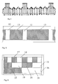
- Fig. 1 is a schematic representation of a position measuring device after the Transmitted light principle shown with a measuring standard in the form of a scale, insofar as it is for the presentation of the invention is required.
- the position measuring device comprises a Scale 1 with a transparent graduation carrier, which has a measuring graduation structure 3, the a scanning head 2 scans in the transmitted light method.
- the measuring graduation structure 3 has light and Dark field areas, the structure of which will be explained later.
- the scanning head 2 has an illumination unit 4 which is transmitted by a Illumination side emits largely parallel light 5 on the scale 1, and one Detection unit 6, which the measuring graduation structure 3 on the lighting side opposite side of the scale 1 scans.
- the measuring graduation structure 3 is as incremental grid division.
- the details of the measuring graduation structure 3 for use in the transmitted light method are in one basic representation shown in Fig. 2.
- the incremental measuring graduation structure 3 that too is referred to as a raster structure, bright field areas 8, which are located in one plane, horizontally shown fields 7 are formed, about the same size as Darkfield areas 11.
- the darkfield areas 11 are totally reflective and surfaces 9 and 10 inclined with respect to the plane of the horizontal fields 7 are produced.
- the light 5, that strikes the horizontal fields 7 of the bright field regions 8 from the lighting side can pass through freely. On the detector side facing away from the lighting unit bright field areas 8 therefore light up.
- the areas of the inclined surfaces 9 and 10 the light from the lighting side is totally reflected and thus at the passage hindered by the scale 1.
- Two adjacent inclined surfaces 9 and 10 form one Prism structure, which is dimensioned such that the on each inclined surface 9 or 10 incident light is deflected by 90 °.
- the parallel light 5 radiated in on the illumination side is transmitted to the respective corresponding inclined surfaces 9 and 10 of the prism structure within the Measuring graduation structure 3 reflected twice by 90 ° and thus back to the lighting side thrown back. It does not get to the detector side. This creates on the Illumination side opposite detector side in transmitted light operation non-illuminating Dark field areas 11, as also shown in FIG. 3.
- FIG. 3 shows this incremental measuring graduation structure 3 in the transmitted light method from the detector side considered with the luminous bright field areas 8 and the non-luminous and therefore Dark-field areas shown hatched 11.
- the ones that can be obtained from this on the detector side optical scanning signals are in the usual way (not shown) via photodiodes and further electrical components converted into electrical signals for evaluation be fed to a control unit or a counter.
- the scale 1 can also be used in the incident light process. This is the scanning unit arranged on the same side of the scale as the lighting unit. While now that parallel light radiated in the area of the inclined surfaces for illumination and Scanning unit is reflected and thus the inclined surfaces 9 and 10, the bright field areas form, the incident light in the area of the horizontal fields 7 passes through the scale therethrough. The fields 7 are therefore the dark field areas. This allows the same scale can be used both in transmitted light and in reflected light, whereby only bright and Change dark fields.
- FIG. 4 shows a measuring graduation structure in a sectional view with reference marks.
- Such reference marks are characterized in that the otherwise constant length of the Brightfield areas 12 and darkfield areas 13 vary.
- the reference mark used in the Embodiment of FIG. 4 shown with double length by a dark field is generated by double the number for this dark field area Prism structures, compared to the other dark field areas, directly abutting are arranged.
- FIG. 5 shows the measuring graduation structure of FIG. 4 in transmitted light mode from the detector side the luminous bright field regions 12 and the non-luminous dark field regions 13, wherein the longer dark field area 13 (on the right in FIG. 5) forms a reference mark.
- the dark field areas 17 are realized by prism structures analogous to FIG. 2. You have like the bright field areas 18 have a base length of 20 ⁇ m.
- the absolute track 15 with the opposite of the Absolute track 14 is twice as long brightfield areas 19 and darkfield areas 20 generated that the bright field areas 19 are each 40 microns long.
- For the dark field areas 20 two identical 45 ° prism structures are lined up so that also the dark field areas 20 have a length of 40 ⁇ m.
- Bright field areas 21 with a length of 80 ⁇ m are arranged for the absolute track 16 and between them four prism structures with a base length of 20 ⁇ m are strung together, see above that the dark field areas 22 also have a length of 80 ⁇ m.
- 7a and 7b show measuring standards for angle measurement in the form of a code disk 23 with a measuring division structure as circular divisions.
- 7a is a top view of the code disk 23 made of optically transparent plastic, e.g. made of polyamide, with brightfield areas 24 and Dark field areas 25.
- optically transparent plastic e.g. made of polyamide
- dark field areas 25 In order to achieve the same duty cycle between the To reach brightfield areas 24 and darkfield areas 25 are these areas designed like pie slices.
- the prism structures 26, as shown in FIG Center to the extent continuously worked deeper into the material, so that their radial width decreases towards the center of the code disk 23.
- Fig. 8 shows a cross section through a schematic diagram of a scale with a fixed Glass-plastic composite. Differences between act particularly in linear measuring devices the thermal expansion coefficient of the test object and measuring standard is unfavorable out. Because the coefficient of expansion of the material measure of the material measure Graduation carrier is determined for very small coefficients of thermal expansion Graduation carriers made of quartz glass or Zerodur are used or to adapt well to steel to achieve special flint glasses.
- the measuring graduation structures according to the invention in optical plastics, but on the other hand also a low thermal Achieving expansion coefficients of the material measure is in the embodiment of the 8 shows a scale made of a solid material composite between a graduation carrier 27 inexpensive borofloat glass with a thickness of 2 mm and a measuring graduation body 28 a polycarbonate layer of 0.3 mm thickness is used.
- a specially made The hot stamping tool in the graduation carrier 27 the structures 29 on commercially available Hot stamping machines, such as those from Jenoptik AG, Jena, Germany, are offered, manufactured, with the dark field areas described at the beginning be formed. It can be used with simple and, above all, inexpensive technologies very dimensionally correct measuring standards in the form of composite scales or precision angular circles getting produced.
- FIG A development of the material measure is shown in FIG is protected against contamination.
- Dirt particles such as water vapor or oil droplets would be removed at the interfaces of the Prismatic structures disturbed the conditions for total reflection, and the light was not defined redirected in scale. This could result in disturbing extraneous light in the dark field.
- the prism structures are covered with a coating, e.g. one commercially available light-tight optical varnish covered, and the surface of the graduation carrier is planarized by applying adapters 30.
- the highly viscous optical lacquer can for example, in a simple manner. Alternatively, it can also be reflective be trained. It ensures that the total reflection conditions are maintained.
- planarization of the surface is advantageously achieved in that disruptive dirt particles stick much less easily or can be removed more easily.
- Figure 10 shows one Position measuring device that works on the transmitted light principle, but in which nevertheless The lighting unit and scanning head are arranged on the same side of the scale can, similar to the incident light principle.
- An optically transparent polyamide injection molded part is used as the division carrier 31
- Two optically reflecting reflection surfaces 32 and 33 over its entire longitudinal extent has, which are at a prism angle of 90 ° to each other. That from the Illumination unit 34 of scanning unit 36 emits parallel light at 45 ° Reflection surfaces 32 and is deflected by 90 ° and within the graduation carrier Reflecting surface 33 totally reflected. The light hits it again at 45 °, it turns deflected by 90 ° and thus reaches a measuring graduation structure within the graduation carrier 37, as described for example in the exemplary embodiment with reference to FIGS. 2 and 3 has been.
- a detection unit 36 with a photodiode array 38 detects that of the Measuring division structure transmitted radiation and emits position-dependent measurement signals.
- the Graduation carrier 31 of the material measure thus causes a beam deflection.
- detection unit 3 and Photodiode array 38 are then z. B. at a 90 ° angle to each other.
- Fig. 11 shows a cross section through a material measure for use in Position measuring method according to Fig. 10.
- measuring standards are the required dimensional accuracy with optically transparent It is difficult to reach plastics because of the temperature-related measurement error the high thermal expansion coefficient of the plastic is difficult to control is.
- the achievable is due to the low mechanical modulus of elasticity Accuracy of measurement with a measuring graduation structure embossed directly into the measuring standard great lengths not very high.
- This can be improved by a separate one Support element as graduation carrier 39 made of an optically transparent polyamide extruded profile is used, which has two optically polished over its entire length Has reflection surfaces 40 and 41.
- the division carrier 39 is special as an extruded profile Can also be produced inexpensively in large lengths.
- the reflection surfaces 40 and 41 of this graduation carrier 39 are also at an angle of 90 ° inclined towards each other. That of the lighting unit, not shown here emitted light 42 strikes the reflection surface 40 at 45 °, and is thereby 90 ° deflected and totally reflected within the graduation carrier to the reflection surface 41. To this hits the light 42 again at an angle of 45 °, is deflected by 90 ° and reaches a glass body 43 with a chromium thin-film measuring division structure 44 known per se Improvement of the light transition between the division carrier 39 made of polyamide and the Glass body 43 is located in the specially for receiving the glass body 43 provided groove 45 as immersion liquid 46 a thin non-volatile silicone oil layer.
- the Graduation carrier 39 with a special receiving profile 47 made of steel with a hardening Glue 48 glued.
Landscapes
- Physics & Mathematics (AREA)
- General Physics & Mathematics (AREA)
- Optics & Photonics (AREA)
- Optical Transform (AREA)
Abstract
Description
- Fig. 1
- einen Querschnitt durch eine Prinzipdarstellung einer Meßanordnung zur Durchlichtpositionsmessung mit einer erfindungsgemäßen Meßteilung;
- Fig. 2
- einen Querschnitt durch eine Prinzipdarstellung eines erfindungsgemäßen Maßstabes mit einer inkrementalen Meßteilung;
- Fig. 3
- eine Draufsicht auf einen Maßstab mit einer inkrementalen Meßteilung;
- Fig. 4
- einen Querschnitt durch eine Prinzipdarstellung eines erfindungsgemäßen Maßstabes mit einer Referenzmarkenstruktur;
- Fig. 5
- eine Draufsicht auf einen Ausschnitt eines Maßstabes mit einer Referenzmarkenstruktur;
- Fig. 6
- eine Draufsicht auf einen Ausschnitt eines Maßstabes mit einer absoluten Meßteilung in mehreren Meßspuren;
- Fig. 7a und 7b
- einen Querschnitt und eine Draufsicht auf einer Teilscheibe mit keilförmigen Teilungsmarken;
- Fig. 8
- einen Querschnitt durch eine Prinzipdarstellung eines Maßstabes der aus einem festen Glas-Kunststoffverbund besteht;
- Fig. 9
- einen Querschnitt durch eine Prinzipdarstellung eines Maßstabes bei dem die trapezförmigen Teilungsmarkenstrukturen planarisiert sind;
- Fig. 10
- eine Prinzipdarstellung einer Positionsmeßeinrichtung mit einem erfindungsgemäßen Maßstab, dessen Meßteilungsstrukturen im Durchlicht abgetastet werden, wobei die Beleuchtung und Abtastung von einer Seite erfolgen;
- Fig. 11
- einen Querschnitt durch einen stranggezogenen Teilungsträger mit Strahlumlenkung und Glasträger, und
- Fig.12
- einen Querschnitt durch einen transparenten Teilungsträger mit integrierten Montageelementen.
Claims (17)
- Maßverkörperung (1) für Positionsmeßsysteme, die als Amplitudengitter ausgebildet ist und eine Meßteilungsstruktur (3) aufweist, die Hellfeldbereiche (8) aufweist, in denen an der Maßverkörperung (1) eingestrahlte Strahlung (5) austritt, und Dunkelfeldbereiche (11), an denen eingestrahlte Strahlung (5) nicht austritt, wobei die Hellfeldbereiche (8) oder die Dunkelfeldbereiche (11) in einer Ebene liegen, dadurch gekennzeichnet, daß die Strahlung (5), die auf zumindest einen der beiden Bereiche trifft, durch mindestens eine Fläche (9 bzw. 10) reflektiert wird, die an der Maßverkörperung (1) ausgebildet ist und zu der Ebene geneigt ist.
- Maßverkörperung (1) nach Anspruch 1, dadurch gekennzeichnet, daß die geneigte Fläche (9 bzw. 10) zur Totalreflektion der Strahlung (5) ausgebildet ist.
- Maßverkörperung (1) nach einem der obigen Ansprüche, dadurch gekennzeichnet, daß die geneigte Fläche (9 bzw. 10) an Grenzflächen von V-förmigen Vertiefungen in der Maßverkörperung (1) gebildet ist.
- Maßverkörperung (1) nach einem der obigen Ansprüche, dadurch gekennzeichnet, daß die geneigte Fläche (9 bzw. 10) an Grenzflächen von Vertiefungen in der Maßverkörperung (1) gebildet ist, die Prismenstruktur aufweisen.
- Maßverkörperung (1) nach einem der Ansprüche 3 oder 4, dadurch gekennzeichnet, daß die Vertiefungen untereinander und/oder in sich unterschiedlich tief sind.
- Maßverkörperung (1) nach einem der Ansprüche 3 bis 5, dadurch gekennzeichnet, daß zur Erzeugung einer Referenzmarkenstruktur mehrere Vertiefungen direkt anschließend nebeneinander angeordnet sind, so daß sich an der Oberfläche der Maßverkörperung (1) in der Längsansicht quer zur Bestrahlungsrichtung gesehen ein Zick-Zack-Profil ergibt.
- Maßverkörperung (1) nach einem der Ansprüche 3 bis 6, dadurch gekennzeichnet, daß die Vertiefungen zur Planarisierung der Oberfläche der Maßverkörperung (1) mit Paßstücken (30) gefüllt sind, die gegenüber dem Material der Maßverkörperung (1) einen deutlichen Brechzahlunterschied aufweisen.
- Maßverkörperung (1) nach einem der Ansprüche 3 bis 7, dadurch gekennzeichnet, daß die geneigte Fläche (9 bzw. 10) der Vertiefungen mit einer Beschichtung versehen ist.
- Maßverkörperung (1) nach einem der Ansprüche 3 bis 8, dadurch gekennzeichnet, daß zur Erzeugung einer Absolutcodierung mehrere Spuren mit Hellfeld- und Dunkelfeldbereichen nebeneinander angeordnet sind.
- Maßverkörperung (1) nach einem der obigen Ansprüche, dadurch gekennzeichnet, daß sie einen einen Grundkörper bildenden Teilungsträger Werkstoff und einen darauf befestigten eine Meßteilungsstruktur aufweisenden Meßteilungskörper aus Kunststoff umfaßt.
- Maßverkörperung (1) nach Anspruch 1 oder 2 zur Verwendung im Auflichtverfahren, dadurch gekennzeichnet, daß eine zur Einstrahlung von Strahlung (42) ausgebildete Einstrahlungsfläche und eine zur Detektion eingestrahlter Strahlung ausgebildete Detektionsfläche aufweist, wobei Einstahlungs- und Detektionsfläche auf einander nicht gegenüberliegenden Seiten der Maßverkörperung liegen und wobei die geneigte Fläche (32, 33) zu Strahlungsumlenkung von der Einstrahlungsfläche zur Detektionsfläche geeignet ausgebildet ist.
- Maßverkörperung (1) nach Anspruch 11, dadurch gekennzeichnet, daß auf der Detektionsfläche ein Meßteilungskörper (37) angeordnet ist, der die Meßteilungsstruktur aufweist.
- Maßverkörperung (1) nach Anspruch 12, dadurch gekennzeichnet, daß die Einstrahlungsfläche, die Detektionsfläche und die geneigte Fläche (32, 33) in einem Teilungsträger (31) gebildet sind, der optisch transparenten Kunststoff, vorzugsweise Polyamid, aufweist, und daß der Meßteilungskörper (37) Glas aufweist.
- Maßverkörperung (1) nach Anspruch 13, dadurch gekennzeichnet, daß der Teilungsträger (39) mit einem Aufnahmeprofil (47) aus Stahl verklebt ist.
- Maßverkörperung (1) nach Anspruch 13 oder 14, dadurch gekennzeichnet, daß der Meßteilungskörper (43) in eine Nut im Teilungsträger (39) eingesetzt ist, die eine nichtflüchtige Immersionsflüssigkeit (46) zur Verbesserung des Lichtübergangs zwischen Teilungsträger (39) und Meßteilungskörper (43) aufweist.
- Verfahren zur Herstellung einer Maßverkörperung (1) nach einem der obigen Ansprüche, dadurch gekennzeichnet, daß die Maßverkörperung (1) mittels Spritzgießen, Extrusion, Heiß- oder Kaltprägen oder Gußtechnik hergestellt wird.
- Verfahren zur Herstellung einer Maßverkörperung (1) nach Anspruch 10, dadurch gekennzeichnet, daß der Meßteilungskörper nach einem der in Anspruch 16 genannten Verfahren hergestellt und mit einem Teilungsträger fest verbunden wird.
Applications Claiming Priority (2)
| Application Number | Priority Date | Filing Date | Title |
|---|---|---|---|
| DE10144927 | 2001-09-12 | ||
| DE10144927 | 2001-09-12 |
Publications (2)
| Publication Number | Publication Date |
|---|---|
| EP1293758A1 true EP1293758A1 (de) | 2003-03-19 |
| EP1293758B1 EP1293758B1 (de) | 2010-05-05 |
Family
ID=7698775
Family Applications (1)
| Application Number | Title | Priority Date | Filing Date |
|---|---|---|---|
| EP20020018094 Expired - Lifetime EP1293758B1 (de) | 2001-09-12 | 2002-08-13 | Massverkörperung für Positionsmesssysteme |
Country Status (2)
| Country | Link |
|---|---|
| EP (1) | EP1293758B1 (de) |
| DE (1) | DE50214409D1 (de) |
Cited By (2)
| Publication number | Priority date | Publication date | Assignee | Title |
|---|---|---|---|---|
| DE102008008377B3 (de) * | 2008-02-09 | 2009-09-24 | Harmonic Drive Ag | Maßverkörperung und Absolutwertgeber |
| DE102011083018A1 (de) | 2011-09-20 | 2013-03-21 | Dr. Johannes Heidenhain Gmbh | Optisches Positionsmesssystem |
Citations (3)
| Publication number | Priority date | Publication date | Assignee | Title |
|---|---|---|---|---|
| DE2714324A1 (de) * | 1977-03-31 | 1978-10-05 | Leitz Ernst Gmbh | Fotoelektrisches auflicht-wegmessystem |
| DE4006789A1 (de) * | 1990-03-03 | 1991-09-05 | Zeiss Carl Fa | Optisches abtastsystem fuer rasterteilungen |
| US5696584A (en) * | 1995-01-28 | 1997-12-09 | Johannes Heidenhain Gmbh | Phase grating having an unprotected relief structure with a grating structure that causes destructive interference of reflections |
-
2002
- 2002-08-13 EP EP20020018094 patent/EP1293758B1/de not_active Expired - Lifetime
- 2002-08-13 DE DE50214409T patent/DE50214409D1/de not_active Expired - Lifetime
Patent Citations (3)
| Publication number | Priority date | Publication date | Assignee | Title |
|---|---|---|---|---|
| DE2714324A1 (de) * | 1977-03-31 | 1978-10-05 | Leitz Ernst Gmbh | Fotoelektrisches auflicht-wegmessystem |
| DE4006789A1 (de) * | 1990-03-03 | 1991-09-05 | Zeiss Carl Fa | Optisches abtastsystem fuer rasterteilungen |
| US5696584A (en) * | 1995-01-28 | 1997-12-09 | Johannes Heidenhain Gmbh | Phase grating having an unprotected relief structure with a grating structure that causes destructive interference of reflections |
Cited By (2)
| Publication number | Priority date | Publication date | Assignee | Title |
|---|---|---|---|---|
| DE102008008377B3 (de) * | 2008-02-09 | 2009-09-24 | Harmonic Drive Ag | Maßverkörperung und Absolutwertgeber |
| DE102011083018A1 (de) | 2011-09-20 | 2013-03-21 | Dr. Johannes Heidenhain Gmbh | Optisches Positionsmesssystem |
Also Published As
| Publication number | Publication date |
|---|---|
| EP1293758B1 (de) | 2010-05-05 |
| DE50214409D1 (de) | 2010-06-17 |
Similar Documents
| Publication | Publication Date | Title |
|---|---|---|
| EP2394143B1 (de) | Optoelektronische lagemesseinrichtung und optoelektronisches lagemessverfahren | |
| DE69605265T2 (de) | Beleuchtungssystem mit integriertem Mikroteleskop in einer durchsichtigen Platte | |
| DE102007007311B4 (de) | Abtasteinheit für eine Positionsmesseinrichtung zur Detektion von optischen Maßverkörperungen sowie entsprechende Positionsmesseinrichtung | |
| DE69011918T3 (de) | Kodiereinrichtung. | |
| EP0137099B1 (de) | Messeinrichtung | |
| DE19830925A1 (de) | Abtasteinheit für eine optische Positionsmeßeinrichtung | |
| EP0978708B1 (de) | Rotatorische Positionsmesseinrichtung | |
| DE10058239A1 (de) | Positionsmeßeinrichtung | |
| DE102020003758A1 (de) | Gitterteil und herstellungsverfahren hierfür | |
| DE19621188B4 (de) | Optischer Sensor zur Bestimmung des Drehwinkels einer Drehachse | |
| EP1293758B1 (de) | Massverkörperung für Positionsmesssysteme | |
| EP1801546B1 (de) | Informationsträger in einem Encoder | |
| DE10033263A1 (de) | Optische Positionsmesseinrichtung | |
| EP1377799B1 (de) | Optische positionsmesseinrichtung | |
| DE19855307B4 (de) | Abtasteinheit für eine optische Positionsmeßeinrichtung | |
| WO2004010170A1 (de) | Optische positions- oder längenbestimmung | |
| DE102004002683A1 (de) | Optische Positions- oder Längenbestimmung | |
| DE10246268B4 (de) | Encoderanordnung | |
| DE10025410A1 (de) | Interferometrische Positionsmesseinrichtung | |
| DE102004011146A1 (de) | Drehgeber und Verfahren zum Betreiben eines Drehgebers | |
| DE3322738C1 (de) | Lichtelektrische Längen- oder Winkelmeßeinrichtung | |
| DE10063899A1 (de) | Optisches Winkelmeßsystem | |
| DE19923505A1 (de) | Rotatorische Positionsmeßeinrichtung | |
| WO2005071363A1 (de) | Drehgeber und verfahren zum betreiben eines drehgebers | |
| DE20320576U1 (de) | Optisches Geberelement zur Positions- oder Längenbestimmung |
Legal Events
| Date | Code | Title | Description |
|---|---|---|---|
| PUAI | Public reference made under article 153(3) epc to a published international application that has entered the european phase |
Free format text: ORIGINAL CODE: 0009012 |
|
| AK | Designated contracting states |
Kind code of ref document: A1 Designated state(s): AT BE BG CH CY CZ DE DK EE ES FI FR GB GR IE IT LI LU MC NL PT SE SK TR Designated state(s): AT BE BG CH CY CZ DE DK EE ES FI FR GB GR IE IT LI LU MC NL PT SE SK TR |
|
| AX | Request for extension of the european patent |
Extension state: AL LT LV MK RO SI |
|
| 17P | Request for examination filed |
Effective date: 20030327 |
|
| AKX | Designation fees paid |
Designated state(s): DE |
|
| RAP1 | Party data changed (applicant data changed or rights of an application transferred) |
Owner name: DR. JOHANNES HEIDENHAIN GMBH |
|
| GRAP | Despatch of communication of intention to grant a patent |
Free format text: ORIGINAL CODE: EPIDOSNIGR1 |
|
| GRAS | Grant fee paid |
Free format text: ORIGINAL CODE: EPIDOSNIGR3 |
|
| GRAA | (expected) grant |
Free format text: ORIGINAL CODE: 0009210 |
|
| AK | Designated contracting states |
Kind code of ref document: B1 Designated state(s): DE |
|
| REF | Corresponds to: |
Ref document number: 50214409 Country of ref document: DE Date of ref document: 20100617 Kind code of ref document: P |
|
| PLBE | No opposition filed within time limit |
Free format text: ORIGINAL CODE: 0009261 |
|
| STAA | Information on the status of an ep patent application or granted ep patent |
Free format text: STATUS: NO OPPOSITION FILED WITHIN TIME LIMIT |
|
| 26N | No opposition filed |
Effective date: 20110208 |
|
| REG | Reference to a national code |
Ref country code: DE Ref legal event code: R097 Ref document number: 50214409 Country of ref document: DE Effective date: 20110207 |
|
| PGFP | Annual fee paid to national office [announced via postgrant information from national office to epo] |
Ref country code: DE Payment date: 20120822 Year of fee payment: 11 |
|
| PG25 | Lapsed in a contracting state [announced via postgrant information from national office to epo] |
Ref country code: DE Free format text: LAPSE BECAUSE OF NON-PAYMENT OF DUE FEES Effective date: 20140301 |
|
| REG | Reference to a national code |
Ref country code: DE Ref legal event code: R119 Ref document number: 50214409 Country of ref document: DE Effective date: 20140301 |