EP1293683A2 - Elektrischer Ventilator mit Langwelleninfrarotröntgenlampe - Google Patents
Elektrischer Ventilator mit Langwelleninfrarotröntgenlampe Download PDFInfo
- Publication number
- EP1293683A2 EP1293683A2 EP02075503A EP02075503A EP1293683A2 EP 1293683 A2 EP1293683 A2 EP 1293683A2 EP 02075503 A EP02075503 A EP 02075503A EP 02075503 A EP02075503 A EP 02075503A EP 1293683 A2 EP1293683 A2 EP 1293683A2
- Authority
- EP
- European Patent Office
- Prior art keywords
- far infrared
- infrared ray
- ray lamp
- electric fan
- blower fan
- Prior art date
- Legal status (The legal status is an assumption and is not a legal conclusion. Google has not performed a legal analysis and makes no representation as to the accuracy of the status listed.)
- Withdrawn
Links
Images



Classifications
-
- F—MECHANICAL ENGINEERING; LIGHTING; HEATING; WEAPONS; BLASTING
- F04—POSITIVE - DISPLACEMENT MACHINES FOR LIQUIDS; PUMPS FOR LIQUIDS OR ELASTIC FLUIDS
- F04D—NON-POSITIVE-DISPLACEMENT PUMPS
- F04D29/00—Details, component parts, or accessories
- F04D29/70—Suction grids; Strainers; Dust separation; Cleaning
- F04D29/701—Suction grids; Strainers; Dust separation; Cleaning especially adapted for elastic fluid pumps
- F04D29/703—Suction grids; Strainers; Dust separation; Cleaning especially adapted for elastic fluid pumps specially for fans, e.g. fan guards
Definitions
- the present invention relates to an electric fan with a far infrared ray lamp serving as a hyperthermic therapy appliance. More particularly, the present invention relates to an electric fan with a far infrared ray lamp serving as a hyperthermic therapy appliance, wherein hyperthermic heat discharged from the far infrared ray lamp and blown air of the electric fan can be independently or simultaneously used, to ensure that a wound heals, a pain is relieved, and muscle aching due to stress, etc. is eased and restores its functionality in a short period of time, while the body and hair are dried in the current of the electric fan, for example, after taking a shower or a bath.
- X-rays are very dangerous to the human body
- exposure to X-rays must be minimized as much as possible when they are utilized for medical diagnosis.
- skin cancer may be caused.
- excessive exposure to electromagnetic waves produced from a radiotelephone or a TV may induce various side effects such as a swollen face and pain.
- electromagnetic far infrared rays are not only harmless to humans, but they also promote metabolism by promoting blood circulation in capillaries. Therefore, exposure to far infrared rays is desirable.
- a steam bath which was created in prehistoric times and uses a principle that far infrared rays are produced when heat of burning firewood passes through mud, can be regarded as an early sauna using far infrared rays.
- far infrared rays are widely used in medical treatment instruments, a thermometer, sensors, radio communication equipment, an exploration system, etc.
- Far infrared rays beneficial to the human body as described above are not popularized in such a way as to be conveniently used in daily life, and a typical way to use far infrared rays is limited only by the physical therapy appliance employed in a hospital or an auxiliary device for a kneader. Therefore, it is difficult for individuals to experience efficacy of far infrared rays. In this connection, upon using a far infrared ray sauna for individuals, a location-related limitation cannot but be imposed on users, and expenses are incurred.
- the body is usually dried with a towel or electric fan after taking a shower, this may be inconvenient since a substantial period of time is required to completely dry the body.
- the hair is usually dried employing a hair drier, hair may be damaged due to the use of the hair drier.
- a hot towel or a hot pack in which a gelatin ingredient is contained is brought into contact with the skin, so as to provide hyperthermic therapy.
- this method is wearisome and inefficacious.
- an object of the present invention is to provide an electric fan with a far infrared ray lamp serving as a hyperthermic therapy appliance, wherein the far infrared ray lamp for irradiating far infrared rays beneficial to the human body is fixedly disposed in front of a blower fan unit of the electric fan so as to independently or simultaneously utilize hyperthermic heat discharged from the far infrared ray lamp and air blown by the electric fan, thereby ensuring healthy drying of the body and hair, fomentation of an aching portion, and relief of fatigue due to stress.
- an electric fan having control means for controlling entire operation of the electric fan, including a rotational velocity, an operation time and a wind direction, driving means for driving a blower fan unit in response to a driving signal outputted from the control means, and front and rear safety nets, characterized in that a far infrared ray lamp is attached to the front safety net, a lamp protective net coated with ceramic is placed at a front end of the far infrared ray lamp in such a way as to decrease a heat conductivity, the control means includes a hyperthermic heat timer, and a case and an outer wall, as a whole, of the electric fan are made of FRP-based synthetic resin which is heat-resistant, light and solid when compared to the conventional plastic material.
- an electric fan having a driving motor, a blower fan unit and a safety net, characterized in that a heat generation device comprising a far infrared ray lamp is located in front of the blower fan unit to enable hyperthermic heat discharged from the far infrared ray lamp and air blown by the electric fan to be independently or simultaneously utilized, and the electric fan includes control and display means for adjusting a wind direction, a wind speed, a rotational velocity, an operation time of the electric fan, a heat generation time of the far infrared ray lamp, etc.
- an electric fan according to the present invention comprises an upper end section having a driving motor 10, a blower fan unit 14 and front and rear safety nets 16 and 12, a support bracket 30 and a control section 40.
- the electric fan is combined with a far infrared ray lamp so as to further serve as a hyperthermic therapy appliance. Therefore, an electric fan with a far infrared ray lamp serving as a hyperthermic therapy appliance in accordance with a first embodiment of the present invention will be described below.
- FIG. 1 is an exploded perspective view illustrating an electric fan with a far infrared ray lamp serving as a hyperthermic therapy appliance in accordance with a first embodiment of the present invention
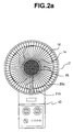
- FIG. 2a is a front view of the electric fan with a far infrared ray lamp serving as a hyperthermic therapy appliance in accordance with the first embodiment of the present invention
- FIG. 2b is a partially broken-away side view of the electric fan with a far infrared ray lamp serving as a hyperthermic therapy appliance in accordance with the first embodiment of the present invention.
- an AC power line is led from an upper part of the support bracket 30 and then connected to a far infrared ray lamp 23.
- the front and rear safety nets 16 and 12 are made of stainless steel-based material which underwent a coating process on a surface thereof.
- the front and rear safety nets 16 and 12 are fastened to each other by a fastening ring 17 which is made of plastic material.
- Reference numeral 21 representatively designates a pair of connectors 21a and 21b which are joined to the fastening ring 17 so that power is supplied through the pair of connectors 21a and 21b.
- a far infrared ray lamp power device 20 which is led from an upper part of the support bracket 32, passes through the rear safety net 12 which underwent the coating process on its surface. Then, after passing through the pair of connectors 21a and 21b which are joined to the fastening ring 17 for fastening the front and rear safety nets 16 and 12 to each other, the far infrared ray lamp power device 20 is connected to the front safety net 16.
- power is applied from a power line leading part 20a which is led from the upper part of the support bracket 30 to a first connection part 20b which is arranged on the rear safety net 12, from the first connection part 20b to the pair of connectors 21a and 21b which are joined to the fastening ring 17, and from the pair of connectors 21a and 21b to a second connection part 20c which is arranged on the front safety net 16.
- the far infrared ray lamp power device 20 which is connected to the front safety net 16 in this way, supplies power to the far infrared ray lamp 23 through a socket 22. At this time, the socket 22 is positioned in front of the blower fan unit 14.
- a far infrared ray lamp part which includes the socket 22 and the far infrared ray lamp 23 is accommodated in an insulating member 24 in such a way as to be surrounded thereby.
- the insulating member 24 has a truncated hollow cone-shaped configuration.
- the far infrared ray lamp part is secured with respect to the front safety net 16 by the medium of the insulating member 24.
- Through another connection part which extends from the second connection part 20c to the inside of the insulating member 24, power is supplied to the socket 22.
- the insulating member 24 is defined with a plurality of holes so as to prevent a temperature around the far infrared ray lamp 23 from rising.
- the blower fan unit 14 and the far infrared ray lamp 23 are independently or simultaneously operated, the blower fan unit 14 is not adversely influenced by heat generation of the far infrared ray lamp 23. Also, since the far infrared ray lamp 23 is independent of rotation of the blower fan unit 14, its reliable and safe heat generation is ensured.
- the upper end section of the electric fan which upper end section has the driving motor 10, has an outer wall made of FRP-based material which is heat-resistant.
- the blower fan unit 14 and the far infrared ray lamp 23 are disposed between the front and rear safety nets 16 and 12.
- a lamp protective net 25 which is resistant against heat of far infrared rays, is secured to the front safety net 16 in front of the far infrared ray lamp 23 serving as a heat generating part. Due to the fact that the lamp protective net 25 is structured so as to be easily attached to or detached from the front safety net 16, it is possible to conveniently replace the far infrared ray lamp 23 with new one.
- the control section 40 serves as control and display means for adjusting a wind direction, a wind speed, a rotational velocity, an operation time of the electric fan, a heat generation time of the far infrared ray lamp 23, etc. and for enabling the blower fan unit 14 and the far infrared ray lamp part to be independently or simultaneously utilized.
- FIG. 3 is a schematic exploded perspective view illustrating an electric fan with a far infrared ray lamp serving as a hyperthermic therapy appliance in accordance with a second embodiment of the present invention
- FIG. 4 is a side cross-sectional view of the electric fan with a far infrared ray lamp serving as a hyperthermic therapy appliance in accordance with the second embodiment of the present invention.
- an output shaft 11 of the driving motor 10 which is positioned at the upper part of the support bracket 30 is formed to have a pipe-shaped configuration so that a power line leading part 20d having the form of a cable and serving as the far infrared ray lamp power device 20 passes through the output shaft 11 to supply power to the far infrared ray lamp 23.
- the rear safety net 12 is coupled by a safety net fastener 13, and then, the blower fan unit 14 is fastened by the blower fan unit fastener 15.
- the power line leading part 20d is connected to the socket 22 which is positioned in front of the blower fan unit fastener 15, whereby power can be supplied to the far infrared ray lamp 23 fitted into the socket 22.
- the far infrared ray lamp 23 is installed at a front end thereof on the front safety net 16 and protected thereby.
- the front safety net 16 functions to fasten the far infrared ray lamp 23 and at the same time protect the far infrared ray lamp 23 and the blower fan unit 14.
- the lamp protective net 25 which is resistant against heat of far infrared rays is secured to the front safety net 16 in front of the far infrared ray lamp 23 serving as a heat generating part. While it is preferable for the lamp protective net 25 to be structured so as to be easily attached to or detached from the front safety net 16 so that it is possible to conveniently replace the far infrared ray lamp 23 with new one, the lamp protective net 25 can be integrally formed with the front safety net 16.
- the safety net fastener 13, the blower fan unit 14, and the blower fan unit fastener 15 are respectively defined at center portions thereof with holes so that the power line leading part 20d can pass through the holes. Due to the fact that the blower fan unit 14 is fastened to the output shaft 11 of driving motor 10 by the blower fan unit fastener 15 which is threaded around a circumferential outer surface of the output shaft 11, the blower fan unit 14 is integrally rotated with the output shaft 11. Since the power line leading part 20d serving as the far infrared ray lamp power device 20 extends through the output shaft 11 of the driving motor 10, it is possible to supply power to the socket 22 fastened with respect to the front safety net 16, irrespective of the rotating motion of the blower fan unit 14. In this way, rotation of the blower fan unit 14 and heat generation of the far infrared ray lamp 23 are not adversely influenced by each other.
- the electric fan with a far infrared ray lamp serving as a hyperthermic therapy appliance provides advantages in that, since a far infrared ray lamp part is positioned in front of a blower fan unit, it is possible to independently or simultaneously utilize hyperthermic heat discharged from the far infrared ray lamp and air blown by the electric fan.
Landscapes
- Engineering & Computer Science (AREA)
- Mechanical Engineering (AREA)
- General Engineering & Computer Science (AREA)
- Structures Of Non-Positive Displacement Pumps (AREA)
- Radiation-Therapy Devices (AREA)
Applications Claiming Priority (4)
| Application Number | Priority Date | Filing Date | Title |
|---|---|---|---|
| KR2001056310 | 2001-09-12 | ||
| KR1020010056310A KR20010099213A (ko) | 2001-09-12 | 2001-09-12 | 원적외선 램프가 부착된 온열 물리치료기 겸용 선풍기 |
| KR2001074252 | 2001-11-27 | ||
| KR10-2001-0074252A KR100431216B1 (ko) | 2001-11-27 | 2001-11-27 | 원적외선 램프가 부착된 온열 물리치료기 겸용 선풍기 |
Publications (2)
| Publication Number | Publication Date |
|---|---|
| EP1293683A2 true EP1293683A2 (de) | 2003-03-19 |
| EP1293683A3 EP1293683A3 (de) | 2003-10-29 |
Family
ID=26639342
Family Applications (1)
| Application Number | Title | Priority Date | Filing Date |
|---|---|---|---|
| EP02075503A Withdrawn EP1293683A3 (de) | 2001-09-12 | 2002-02-06 | Elektrischer Ventilator mit Langwelleninfrarotröntgenlampe |
Country Status (4)
| Country | Link |
|---|---|
| US (1) | US6610082B2 (de) |
| EP (1) | EP1293683A3 (de) |
| JP (1) | JP2003079751A (de) |
| CN (1) | CN1403719A (de) |
Families Citing this family (12)
| Publication number | Priority date | Publication date | Assignee | Title |
|---|---|---|---|---|
| US8326135B1 (en) * | 2008-01-25 | 2012-12-04 | Gose Kent W | Heat lamp with dispersing fan |
| USD633189S1 (en) * | 2009-11-19 | 2011-02-22 | National Presto Industries, Inc. | Dish-style electric heater |
| EP2908807B1 (de) | 2012-10-19 | 2018-07-25 | Nurman Salim | Hautpflaster zum absorbieren von toxinen aus dem körper |
| DE202012012818U1 (de) | 2012-12-03 | 2013-12-06 | Nurman Salim | Hautpflaster zur Absorbierung von Giftstofffen aus dem Körper |
| CN107218233A (zh) * | 2017-04-18 | 2017-09-29 | 东莞产权交易中心 | 一种多功能电风扇 |
| GB201808949D0 (en) | 2018-05-31 | 2018-07-18 | Micromass Ltd | Bench-top time of flight mass spectrometer |
| GB201808893D0 (en) | 2018-05-31 | 2018-07-18 | Micromass Ltd | Bench-top time of flight mass spectrometer |
| GB201808894D0 (en) | 2018-05-31 | 2018-07-18 | Micromass Ltd | Mass spectrometer |
| GB201808932D0 (en) | 2018-05-31 | 2018-07-18 | Micromass Ltd | Bench-top time of flight mass spectrometer |
| GB201808912D0 (en) | 2018-05-31 | 2018-07-18 | Micromass Ltd | Bench-top time of flight mass spectrometer |
| WO2019229469A1 (en) | 2018-05-31 | 2019-12-05 | Micromass Uk Limited | Mass spectrometer |
| CN108895010A (zh) * | 2018-07-23 | 2018-11-27 | 珠海格力电器股份有限公司 | 一种电风扇的接线结构及电风扇 |
Family Cites Families (9)
| Publication number | Priority date | Publication date | Assignee | Title |
|---|---|---|---|---|
| US1006767A (en) * | 1910-01-19 | 1911-10-24 | Gen Electric | Electric hair-drier. |
| US1674017A (en) * | 1926-03-15 | 1928-06-19 | John E Marsden | Combination electric heater and fan |
| US1961772A (en) * | 1929-07-09 | 1934-06-05 | Martin Brothers Electric Compa | Drier |
| US4263500A (en) * | 1978-06-19 | 1981-04-21 | Clairol Incorporated | Infrared heating hair dryer |
| DE3843552C1 (de) * | 1988-12-23 | 1990-06-13 | Bernhard 5143 Wassenberg De Pfeifer | |
| DE4113803A1 (de) * | 1991-04-24 | 1992-10-29 | Iwg Eastmed Medizintechnik Gmb | Bestrahlungseinrichtung zur oertlichen oder gesamten erwaermung des menschlichen koerpers |
| US5348447A (en) * | 1992-12-30 | 1994-09-20 | J & D Sales | Improved fan housing with easy access |
| KR200195568Y1 (ko) * | 1998-06-26 | 2000-09-01 | 김대성 | 할로겐 헤어드라이기 |
| KR200190425Y1 (ko) * | 2000-03-03 | 2000-08-01 | 최종국 | 히터를 위한 열 발생장치 |
-
2001
- 2001-12-27 JP JP2001396985A patent/JP2003079751A/ja active Pending
- 2001-12-28 US US10/033,348 patent/US6610082B2/en not_active Expired - Fee Related
-
2002
- 2002-01-07 CN CN02101605A patent/CN1403719A/zh active Pending
- 2002-02-06 EP EP02075503A patent/EP1293683A3/de not_active Withdrawn
Also Published As
| Publication number | Publication date |
|---|---|
| JP2003079751A (ja) | 2003-03-18 |
| EP1293683A3 (de) | 2003-10-29 |
| CN1403719A (zh) | 2003-03-19 |
| US6610082B2 (en) | 2003-08-26 |
| US20030050679A1 (en) | 2003-03-13 |
Similar Documents
| Publication | Publication Date | Title |
|---|---|---|
| US5107832A (en) | Universal thermotherapy applicator | |
| US5190031A (en) | Universal thermotherapy applicator | |
| US6610082B2 (en) | Electric fan with far infrared ray lamp | |
| US4667658A (en) | Thermotherapy technique | |
| US4595008A (en) | Localized thermotherapy technique | |
| KR960009890B1 (ko) | 원적외선 발생 조성물을 갖는 휴대용 치료기기 | |
| US5443487A (en) | Combined chemo-thermo therapy technique | |
| WO1998010723A1 (en) | Eye function improving warmer | |
| CN102348446A (zh) | 电温灸器 | |
| US20080228247A1 (en) | Health Care and Physical Therapy Device For Gathering Energy | |
| CN109938991B (zh) | 一种放松器 | |
| JP2000225141A (ja) | 電池温熱式アイマスク | |
| WO2010013259A1 (en) | Device for suction-kneading massage | |
| KR200409904Y1 (ko) | 고주파 전기전극치료기 | |
| KR20130078979A (ko) | 비만과 암 치료용 전신온열장치 | |
| JPS63177856A (ja) | 温熱治療装置 | |
| CN104759036A (zh) | 一种远红外护膝理疗盒 | |
| CN212662470U (zh) | 悬停臂及其治疗仪 | |
| CA2058400A1 (en) | Universal thermotherapy technique | |
| KR100462008B1 (ko) | 치질 방석 | |
| KR100365508B1 (ko) | 원적외선을 이용한 전신온열장치 | |
| CN206453991U (zh) | 红外线光灸装置 | |
| KR100431216B1 (ko) | 원적외선 램프가 부착된 온열 물리치료기 겸용 선풍기 | |
| JP2004105662A (ja) | 生体加温方法 | |
| KR200261824Y1 (ko) | 원적외선 램프가 부착된 온열 물리치료기 겸용 선풍기 |
Legal Events
| Date | Code | Title | Description |
|---|---|---|---|
| PUAI | Public reference made under article 153(3) epc to a published international application that has entered the european phase |
Free format text: ORIGINAL CODE: 0009012 |
|
| AK | Designated contracting states |
Kind code of ref document: A2 Designated state(s): AT BE CH CY DE DK ES FI FR GB GR IE IT LI LU MC NL PT SE TR Designated state(s): AT BE CH CY DE DK ES FI FR GB GR IE IT LI LU MC NL PT SE TR |
|
| AX | Request for extension of the european patent |
Extension state: AL LT LV MK RO SI |
|
| PUAL | Search report despatched |
Free format text: ORIGINAL CODE: 0009013 |
|
| AK | Designated contracting states |
Kind code of ref document: A3 Designated state(s): AT BE CH CY DE DK ES FI FR GB GR IE IT LI LU MC NL PT SE TR |
|
| AX | Request for extension of the european patent |
Extension state: AL LT LV MK RO SI |
|
| RIC1 | Information provided on ipc code assigned before grant |
Ipc: 7A 61N 5/06 B Ipc: 7F 04D 29/70 A |
|
| AKX | Designation fees paid |
Designated state(s): DE ES FR GB IT |
|
| STAA | Information on the status of an ep patent application or granted ep patent |
Free format text: STATUS: THE APPLICATION IS DEEMED TO BE WITHDRAWN |
|
| 18D | Application deemed to be withdrawn |
Effective date: 20040430 |