EP1293654A2 - Système d'injection de carburant pour moteur a combustion interne - Google Patents
Système d'injection de carburant pour moteur a combustion interne Download PDFInfo
- Publication number
- EP1293654A2 EP1293654A2 EP02021233A EP02021233A EP1293654A2 EP 1293654 A2 EP1293654 A2 EP 1293654A2 EP 02021233 A EP02021233 A EP 02021233A EP 02021233 A EP02021233 A EP 02021233A EP 1293654 A2 EP1293654 A2 EP 1293654A2
- Authority
- EP
- European Patent Office
- Prior art keywords
- fuel
- pressure
- tank
- pump
- injection system
- Prior art date
- Legal status (The legal status is an assumption and is not a legal conclusion. Google has not performed a legal analysis and makes no representation as to the accuracy of the status listed.)
- Withdrawn
Links
Images


Classifications
-
- F—MECHANICAL ENGINEERING; LIGHTING; HEATING; WEAPONS; BLASTING
- F17—STORING OR DISTRIBUTING GASES OR LIQUIDS
- F17C—VESSELS FOR CONTAINING OR STORING COMPRESSED, LIQUEFIED OR SOLIDIFIED GASES; FIXED-CAPACITY GAS-HOLDERS; FILLING VESSELS WITH, OR DISCHARGING FROM VESSELS, COMPRESSED, LIQUEFIED, OR SOLIDIFIED GASES
- F17C7/00—Methods or apparatus for discharging liquefied, solidified, or compressed gases from pressure vessels, not covered by another subclass
- F17C7/02—Discharging liquefied gases
-
- F—MECHANICAL ENGINEERING; LIGHTING; HEATING; WEAPONS; BLASTING
- F02—COMBUSTION ENGINES; HOT-GAS OR COMBUSTION-PRODUCT ENGINE PLANTS
- F02D—CONTROLLING COMBUSTION ENGINES
- F02D19/00—Controlling engines characterised by their use of non-liquid fuels, pluralities of fuels, or non-fuel substances added to the combustible mixtures
- F02D19/06—Controlling engines characterised by their use of non-liquid fuels, pluralities of fuels, or non-fuel substances added to the combustible mixtures peculiar to engines working with pluralities of fuels, e.g. alternatively with light and heavy fuel oil, other than engines indifferent to the fuel consumed
- F02D19/0639—Controlling engines characterised by their use of non-liquid fuels, pluralities of fuels, or non-fuel substances added to the combustible mixtures peculiar to engines working with pluralities of fuels, e.g. alternatively with light and heavy fuel oil, other than engines indifferent to the fuel consumed characterised by the type of fuels
- F02D19/0642—Controlling engines characterised by their use of non-liquid fuels, pluralities of fuels, or non-fuel substances added to the combustible mixtures peculiar to engines working with pluralities of fuels, e.g. alternatively with light and heavy fuel oil, other than engines indifferent to the fuel consumed characterised by the type of fuels at least one fuel being gaseous, the other fuels being gaseous or liquid at standard conditions
- F02D19/0647—Controlling engines characterised by their use of non-liquid fuels, pluralities of fuels, or non-fuel substances added to the combustible mixtures peculiar to engines working with pluralities of fuels, e.g. alternatively with light and heavy fuel oil, other than engines indifferent to the fuel consumed characterised by the type of fuels at least one fuel being gaseous, the other fuels being gaseous or liquid at standard conditions the gaseous fuel being liquefied petroleum gas [LPG], liquefied natural gas [LNG], compressed natural gas [CNG] or dimethyl ether [DME]
-
- F—MECHANICAL ENGINEERING; LIGHTING; HEATING; WEAPONS; BLASTING
- F17—STORING OR DISTRIBUTING GASES OR LIQUIDS
- F17C—VESSELS FOR CONTAINING OR STORING COMPRESSED, LIQUEFIED OR SOLIDIFIED GASES; FIXED-CAPACITY GAS-HOLDERS; FILLING VESSELS WITH, OR DISCHARGING FROM VESSELS, COMPRESSED, LIQUEFIED, OR SOLIDIFIED GASES
- F17C13/00—Details of vessels or of the filling or discharging of vessels
- F17C13/02—Special adaptations of indicating, measuring, or monitoring equipment
- F17C13/025—Special adaptations of indicating, measuring, or monitoring equipment having the pressure as the parameter
-
- F—MECHANICAL ENGINEERING; LIGHTING; HEATING; WEAPONS; BLASTING
- F17—STORING OR DISTRIBUTING GASES OR LIQUIDS
- F17C—VESSELS FOR CONTAINING OR STORING COMPRESSED, LIQUEFIED OR SOLIDIFIED GASES; FIXED-CAPACITY GAS-HOLDERS; FILLING VESSELS WITH, OR DISCHARGING FROM VESSELS, COMPRESSED, LIQUEFIED, OR SOLIDIFIED GASES
- F17C13/00—Details of vessels or of the filling or discharging of vessels
- F17C13/02—Special adaptations of indicating, measuring, or monitoring equipment
- F17C13/026—Special adaptations of indicating, measuring, or monitoring equipment having the temperature as the parameter
-
- F—MECHANICAL ENGINEERING; LIGHTING; HEATING; WEAPONS; BLASTING
- F17—STORING OR DISTRIBUTING GASES OR LIQUIDS
- F17C—VESSELS FOR CONTAINING OR STORING COMPRESSED, LIQUEFIED OR SOLIDIFIED GASES; FIXED-CAPACITY GAS-HOLDERS; FILLING VESSELS WITH, OR DISCHARGING FROM VESSELS, COMPRESSED, LIQUEFIED, OR SOLIDIFIED GASES
- F17C9/00—Methods or apparatus for discharging liquefied or solidified gases from vessels not under pressure
-
- F—MECHANICAL ENGINEERING; LIGHTING; HEATING; WEAPONS; BLASTING
- F17—STORING OR DISTRIBUTING GASES OR LIQUIDS
- F17C—VESSELS FOR CONTAINING OR STORING COMPRESSED, LIQUEFIED OR SOLIDIFIED GASES; FIXED-CAPACITY GAS-HOLDERS; FILLING VESSELS WITH, OR DISCHARGING FROM VESSELS, COMPRESSED, LIQUEFIED, OR SOLIDIFIED GASES
- F17C2221/00—Handled fluid, in particular type of fluid
- F17C2221/03—Mixtures
- F17C2221/032—Hydrocarbons
- F17C2221/035—Propane butane, e.g. LPG, GPL
-
- F—MECHANICAL ENGINEERING; LIGHTING; HEATING; WEAPONS; BLASTING
- F17—STORING OR DISTRIBUTING GASES OR LIQUIDS
- F17C—VESSELS FOR CONTAINING OR STORING COMPRESSED, LIQUEFIED OR SOLIDIFIED GASES; FIXED-CAPACITY GAS-HOLDERS; FILLING VESSELS WITH, OR DISCHARGING FROM VESSELS, COMPRESSED, LIQUEFIED, OR SOLIDIFIED GASES
- F17C2227/00—Transfer of fluids, i.e. method or means for transferring the fluid; Heat exchange with the fluid
- F17C2227/01—Propulsion of the fluid
- F17C2227/0128—Propulsion of the fluid with pumps or compressors
- F17C2227/0135—Pumps
-
- F—MECHANICAL ENGINEERING; LIGHTING; HEATING; WEAPONS; BLASTING
- F17—STORING OR DISTRIBUTING GASES OR LIQUIDS
- F17C—VESSELS FOR CONTAINING OR STORING COMPRESSED, LIQUEFIED OR SOLIDIFIED GASES; FIXED-CAPACITY GAS-HOLDERS; FILLING VESSELS WITH, OR DISCHARGING FROM VESSELS, COMPRESSED, LIQUEFIED, OR SOLIDIFIED GASES
- F17C2227/00—Transfer of fluids, i.e. method or means for transferring the fluid; Heat exchange with the fluid
- F17C2227/01—Propulsion of the fluid
- F17C2227/0128—Propulsion of the fluid with pumps or compressors
- F17C2227/0171—Arrangement
- F17C2227/0185—Arrangement comprising several pumps or compressors
-
- Y—GENERAL TAGGING OF NEW TECHNOLOGICAL DEVELOPMENTS; GENERAL TAGGING OF CROSS-SECTIONAL TECHNOLOGIES SPANNING OVER SEVERAL SECTIONS OF THE IPC; TECHNICAL SUBJECTS COVERED BY FORMER USPC CROSS-REFERENCE ART COLLECTIONS [XRACs] AND DIGESTS
- Y02—TECHNOLOGIES OR APPLICATIONS FOR MITIGATION OR ADAPTATION AGAINST CLIMATE CHANGE
- Y02T—CLIMATE CHANGE MITIGATION TECHNOLOGIES RELATED TO TRANSPORTATION
- Y02T10/00—Road transport of goods or passengers
- Y02T10/10—Internal combustion engine [ICE] based vehicles
- Y02T10/30—Use of alternative fuels, e.g. biofuels
Definitions
- the invention relates to a fuel injection system for internal combustion engines according to the preamble of claim 1.
- Injection systems which direct the fuel in liquid form into the Injecting the combustion chamber of an internal combustion engine has been known for a long time and are used, for example, in connection with common rail technology used.
- the direct injection enables a high power yield achieve while keeping fuel consumption relatively low is. For these reasons, this technology is already widely used in the Construction of motor vehicle engines found.
- Fuels such as gasoline or diesel to tap additional fuel sources are particularly suitable for liquefied petroleum gas.
- liquefied petroleum gas is a by-product of the manufacture of petrol and diesel. It can be use with good performance to operate internal combustion engines and leads to lower environmental emissions. This is usually the case a propane-butane mixture, which is also known as LPG (liquefied petroleum gas) referred to as.
- LPG liquefied petroleum gas
- this fuel is gaseous, can, however, by applying a relatively low excess pressure of Keep approx. 6 bar in the liquid state.
- medium pressure fuel in delimitation to low-pressure fuels such as gasoline or liquid at atmospheric pressure Diesel.
- medium pressure fuel can also be used in the above Use direct injection system provided the fuel is under Pressure and thus fluid is kept and in this state in the combustion chamber can be injected.
- Suitable fuel injection systems are already available in different versions known.
- the document EP 0 725 208 B1 shows an injection system, at which liquid gas from a pressurized storage tank is supplied in liquid form to the injection pump.
- a fuel pump is arranged inside the tank, which is the liquid gas promotes in the injection pump supply line.
- US-A 5 291 869 also discloses a liquid gas injection system with a pump arranged in the tank.
- This structure has the advantage that it is structurally simple and inexpensive are.
- the object of the present invention is therefore a fuel injection system to create the type mentioned, through which medium-pressure fuel can be supplied in liquid form to the injection pump without the constructive Effort increases significantly compared to the known systems and without operating problems.
- the fuel injection system is in addition to the Tank arranged fuel pump another, second fuel pump downstream arranged in the injection pump supply line outside the tank. So these two pumps are connected in series so that they are different add generated pressures.
- the pump in the tank ensures that the medium pressure fuel leaves the tank in liquid form and still in this state reached the second pump. This then bends through the additional pressurization another pressure drop before, so that it is ensured that only liquid fuel is supplied to the injection pump.
- This construction is relatively simple in that no change in the Injection pump is necessary, but only a liquid fuel pump must also be installed in the injection pump supply line.
- the performance the pump in the tank can be so limited that it is just sufficient to keep the fuel liquid until the second pump is reached. To a small-sized fuel pump is sufficient for this purpose, so that it there are no problems with accommodation and with regard to waste heat.
- the part of the injection pump supply line can be between the first and the second fuel pump to a comparatively low nominal pressure be designed regardless of the higher ultimate pressure caused by the second Pump is generated.
- the medium-pressure fuel is preferably liquefied petroleum gas (LPG).
- LPG liquefied petroleum gas
- the fuel injection system according to the invention comprises a high pressure valve to control the injection pressure of the Injection pump and a pressure control valve to control the pressure in the Injection pump supply line.
- the injection pump feed line opens a low pressure fuel supply line for feeding one under Atmospheric pressure liquid low pressure fuel from a low pressure fuel source
- the low pressure fuel supply line and the injection pump supply line include means for switching between a fuel supply from the low pressure fuel source and a fuel supply from the Tank.
- This embodiment is a so-called bivalent system, both with low-pressure fuel and with medium-pressure fuel is to be operated and can be used particularly flexibly due to this option is.
- the injection pump is provided for this purpose, either low-pressure fuel such as gasoline or diesel or liquid medium pressure fuel in the Inject the combustion chamber of the internal combustion engine without modifications or supplementing the injection pump compared to a conventional low-pressure fuel system are required.
- low-pressure fuel such as gasoline or diesel or liquid medium pressure fuel in the Inject the combustion chamber of the internal combustion engine without modifications or supplementing the injection pump compared to a conventional low-pressure fuel system are required.
- you can choose between the two operating modes. can in particular serve to act on parts with different pressures to separate the system from one another and, for example, to prevent the system area for feeding in low pressure fuel with the Pressure is applied that prevails in the system area from which the Medium pressure fuel is fed.
- the low-pressure fuel feed line preferably opens at one point downstream of the second fuel pump into the injection pump feed line, see above that both fuel pumps mentioned above serve only the medium pressure fuel component to promote and apply pressure.
- the Switching devices preferably include solenoid valves for switching on or off the fuel supply from the tank or the low pressure fuel source.
- a low pressure fuel pump is arranged which is the low pressure fuel can independently convey into the injection pump supply line.
- the low pressure fuel pump and the series-connected medium pressure fuel pumps can be operated independently of each other. This turns out to control the Pressure ratios in switching operations as advantageous. For example switched from medium pressure fuel to low pressure fuel, so it is possible turn off the medium pressure fuel pumps while the low pressure fuel pump maintains the pressure in the injection pump supply line.
- the medium pressure fuel residues remaining in the supply line are thereby prevented from evaporation and can be fed to the injection pump in liquid form as they are gradually displaced by low pressure fuel become. This helps prevent the occurrence of unwanted gaseous fuel components to prevent completely during switching operations, so that there are no operational or performance disruptions and continuous combustion is possible.
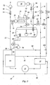
- the fuel injection system 10 shown in FIG. 1 is an injection system suitable for operation with a medium pressure fuel which is gaseous under atmospheric pressure and for liquefaction with a Pressure of at least about 6 bar must be applied.
- a medium pressure fuel which is gaseous under atmospheric pressure and for liquefaction with a Pressure of at least about 6 bar must be applied.
- it can are particularly liquefied gas, which is also known as LPG (Liquified Petroleum Gas) is called and is a propane-butane mixture.
- LPG Liquified Petroleum Gas
- the injection system 10 is constructed according to the common rail principle, i.e. by a manifold 12 shown only schematically in FIG Combustion chamber, not shown, of an engine supplied with fuel. This happens under high pressure by an injection pump 14 which is the pressurized Fuel fed into the rail. Via a high pressure regulator 16, which is connected to the distributor pipe 12, excess, fuel not supplied to the combustion chamber can be derived. simultaneously the high-pressure regulator 16 serves to regulate the pressure in the distributor pipe 12.
- Medium pressure fuel is stored in a tank 20 under a pressure that is higher than the vaporization pressure of the medium pressure fuel.
- the pressure inside the tank 20 is 25 bar, while the blow-off pressure is Tanks 20 is 30 bar.
- the medium pressure fuel becomes the injection pump 14 by an injection pump supply line 22 in the manner explained below fed.
- a first fuel pump 24 is arranged inside the tank and is liquid held medium pressure fuel in the injection pump supply line 22 feeds. In the present case it is a submersible pump.
- the fuel pump 24 can also be suspended from the ceiling of the tank 20.
- the Medium pressure fuel passes in the section outside the tank 20 the injection pump supply line 22 in succession a solenoid valve 26, a heat exchanger 28 and a second fuel pump 30.
- the two fuel pumps 24, 30 are thus connected in series, so that their pressures add.
- the performance of the first fuel pump 24 is such that they pressurize the medium pressure fuel with sufficient pressure is to the medium pressure fuel on its way to the second fuel pump 30 keep fluid.
- the second fuel pump 30 applies a pressure to the medium pressure fuel additional pressure sufficient to fuel the injection pump 14 in to supply liquid form.
- the solenoid valve 26 serves the fuel supply if necessary to switch off completely and thus the operation of the internal combustion engine to interrupt.
- the serial arrangement of the fuel pumps 24, 30 can ensure that only liquid medium pressure fuel always reaches the injection pump 14. Since this is now injected into the combustion chamber in liquid form no more intake air displaced. This increases the degree of filling of the cylinders compared to the injection in the intake tract and thus also the Motor performance.
- a return line 32 is used to keep excess, not in the combustion chamber injected fuel from the high pressure regulator 16 optionally into the injection pump feed line 22 or attributed to the tank 20.
- the return line 32 on the one hand via a cross connection 34 with the injection pump supply line 22 connected and on the other hand itself leads to one Filling line 36, which serves to fill the tank 20 and leads into this.
- medium-pressure fuel can also be produced from a non-illustrated one Medium pressure fuel source to be filled in the tank.
- Check valve 38 arranged. Another check valve 40 at the inlet to tank 20 ensures that the pressure in tank 20 is maintained.
- a lubricant tank 48 feed a lubricant into the tank 20 via the filling line 36 and mix it with the medium pressure fuel that the Can improve operating properties of the fuel. This is the lubricant tank 48 via a corresponding supply line 50 with a lubricant pump 52 and a check valve 54 to prevent backflow connected to the filling line 36.
- An electrical control unit 56 is provided for this purpose, which is connected to two temperature sensors, namely a first temperature sensor 58 in the injection pump supply line at the inlet of the injection pump 14 and a second temperature sensor 60 for measuring the temperature inside the tank 20.
- the control unit 56 is thus able to control the temperature in the tank 20 with that in the injection pump supply line 22 immediately compare before the injection pump 14.
- an electric heater 62 controlled by the electric control unit 46 can be.
- 20 heating mats can be placed on the outside of the tank be attached, or it will be the coolant of the cooler of the internal combustion engine, which is heated by its waste heat, used for heating.
- the tank 20 may be thermally insulated and / or soundproofed exhibit.
- the comparison of the temperatures in the tank 20 and in the injection pump supply line 22 offers the possibility in connection with the electric heater 62. Catch temperature fluctuations in the system better. In particular is it is necessary to compensate for temperature peaks caused by heat conduction within of the system and due to the heat radiation from the internal combustion engine caused. However, it must be guaranteed that the ruling Pressure of the medium pressure fuel at the input of the injection pump 14 always higher is than its vapor pressure.
- the control unit 56 thus compares the temperatures in the tank 20 and at the entrance of the injection pump 14 and reacts if the Difference of the measured values exceeds a predetermined value, with an activation the electric heater 62. In this way it can be ensured that a certain maximum temperature difference is not exceeded becomes. If this falls below, the heating power of the heater 62 can be switched off become.
- FIG. 2 shows a modification of the injection system 10 according to the invention Figure 1.
- the same parts in Figures 1 and 2 provided with identical reference numerals.
- the arrangement of the injection pump supply line 22 for conveying medium-pressure fuel from the tank 20 to the injection pump 14 essentially corresponds Figure 1, in particular the arrangement of the first fuel pump 24 in Tank 20, the downstream second fuel pump 30 and the one in between arranged heat exchanger 28.
- the arrangement from FIG. 2 additionally comprises a low-pressure fuel supply line 70 which is at a point downstream of the second Fuel pump 30 opens into the injection pump feed line 22.
- a low-pressure fuel supply line 70 which is at a point downstream of the second Fuel pump 30 opens into the injection pump feed line 22.
- This is an under Atmospheric pressure liquid fuel such as diesel or gasoline or possibly also vegetable oil.
- suitable feeding and switching devices which are to be explained in the following, can thus be chosen liquid low-pressure fuel or medium-pressure fuel of the injection pump 14 respectively.
- the low pressure fuel supply line 70 also includes a fuel pump 72 for feeding the low-pressure fuel into the injection pump feed line 22. Downstream of this low pressure fuel pump 72 is a check valve 74 arranged, which is a backflow along the low pressure fuel supply line 70 prevented. Upstream of the low pressure fuel pump 72 can in a manner not shown, a feed pump for the transport of low pressure fuel be arranged from a tank so that the downstream Low-pressure fuel pump 72 mainly serves the delivered low-pressure fuel to apply sufficient pressure.
- the injection system of Figure 2 also includes a fuel return system corresponding to FIG. 1.
- a fuel return system corresponding to FIG. 1.
- the fuel return system from Figure 2 enables in particular low-pressure fuel initiate in the medium pressure fuel tank 20 and on this wise to generate a fuel mixture if desired.
- Functions of the temperature sensors 58, 60 and the heater 62 can be found on the explanations be referred in connection with Figure 1.
- the injection system from FIG. 3 differs from that in FIG. 2 essentially through a modified fuel recirculation system as well by a pressure control valve 82 for controlling the input pressure of the injection pump 14.
- the pressure control valve 82 is connected through a control line 84 the return line 32 connected so that excess fuel in the Return line 32 can be returned. It always ensures that only liquid fuel, in particular liquid medium pressure fuel to the injection pump 14 arrives.
- Another control line 86 branches from the injection pump supply line 22 and connects them to the high pressure regulator 16. Through this control line 86, a control piston of the high-pressure regulator 16 When operating with medium-pressure fuel, a pressure is applied that increases added to an already existing spring tension of the piston, so that the desired injection pressure can be achieved.
- the return line 46 emanating from the injection pump 14 runs in this Case directly to the low-pressure fuel source, not shown, the return flow as with the return line 78 through a solenoid valve 88 is regulated.
- a branch line 90 with a check valve 92 is the return line 46 with the return line 32 and the filling line 36 connected so that a return to the tank 20 is also possible from here.
- a solenoid valve 93 is arranged, which is another possibility for Control of fuel flow provides.
- throttling of the return flow through the solenoid valve 93 an increase in pressure reach in front of the valve.
- control valve 82 offers a further possibility for temperature and pressure control.
- the electrical Control unit 56 is able, except for the described comparison of temperatures in the tank 20 and in the injection pump supply line 22 and the corresponding Control of the heater 62 to control a pump 94, which serves to a compensation chamber within the control valve 82 with additional pressure apply. This pressure is added to a spring pressure of the control valve in such a way that the necessary fuel pressure can be achieved.
- a branch line 96 is branched off from the injection pump supply line 22, through which a part of the medium pressure fuel contained in the tank 20 branch off as coolant for operating the heat exchanger 28 and again the engine's intake tract.
- the volume flow through this Branch line 96 can be regulated by a further solenoid valve 98.
- the temperature and thus the pressure immediately before the injection pump 14 can be control by regulating the cooling capacity of the heat exchanger 28 accordingly becomes. This can be done by an appropriate connection to the temperature sensor 58, 60 or the control unit 56 happen.
- the injection system shown in FIG. 3 has a further additional feature 10 a sensor 100 in the return line 46 through which the possibility is given the power of the fuel pump 72 and possibly the valves in the return lines 32, 46, 78 in response to a signal to control the sensor 100.
- the measured size is for example the pressure or the fuel mass flow rate per unit of time.
Landscapes
- Engineering & Computer Science (AREA)
- Mechanical Engineering (AREA)
- General Engineering & Computer Science (AREA)
- Chemical & Material Sciences (AREA)
- Oil, Petroleum & Natural Gas (AREA)
- Combustion & Propulsion (AREA)
- Fuel-Injection Apparatus (AREA)
Applications Claiming Priority (6)
| Application Number | Priority Date | Filing Date | Title |
|---|---|---|---|
| DE10146051A DE10146051B4 (de) | 2001-01-28 | 2001-09-18 | Kraftstoffdirekteinspritzsystem |
| DE10146051 | 2001-09-18 | ||
| DE20209413U DE20209413U1 (de) | 2002-06-17 | 2002-06-17 | Flüssiggastank |
| DE20209413U | 2002-06-17 | ||
| DE10230958 | 2002-07-10 | ||
| DE2002130958 DE10230958A1 (de) | 2001-09-18 | 2002-07-10 | Kraftstoffdirekteinspritzsystem |
Publications (2)
| Publication Number | Publication Date |
|---|---|
| EP1293654A2 true EP1293654A2 (fr) | 2003-03-19 |
| EP1293654A3 EP1293654A3 (fr) | 2004-02-11 |
Family
ID=27214610
Family Applications (1)
| Application Number | Title | Priority Date | Filing Date |
|---|---|---|---|
| EP02021233A Withdrawn EP1293654A3 (fr) | 2001-09-18 | 2002-09-18 | Système d'injection de carburant pour moteur a combustion interne |
Country Status (1)
| Country | Link |
|---|---|
| EP (1) | EP1293654A3 (fr) |
Cited By (5)
| Publication number | Priority date | Publication date | Assignee | Title |
|---|---|---|---|---|
| EP1785618A1 (fr) * | 2005-11-13 | 2007-05-16 | Karlheinrich Winkelmann | Système de refroidissement de carburant pour moteur à combustion interne |
| US20130098334A1 (en) * | 2010-06-22 | 2013-04-25 | A. Luhmann Gmbh | Fuel Metering Device for an Internal Combustion Engine |
| US9506409B2 (en) | 2011-06-24 | 2016-11-29 | Indopar B.V. | Method of switching from a liquefied gas fuel to a liquid fuel being provided to a direct injection combustion engine, and direct injection bi-fuel system for such an engine |
| CN111677611A (zh) * | 2020-06-24 | 2020-09-18 | 天津大学 | 一种内燃机燃料超临界喷射系统及控制方法 |
| DE102012105604B4 (de) * | 2011-12-07 | 2021-05-06 | Hyundai Motor Company | Wärmetauscher für ein Fahrzeug |
Citations (5)
| Publication number | Priority date | Publication date | Assignee | Title |
|---|---|---|---|---|
| DE19611381A1 (de) * | 1995-03-23 | 1996-09-26 | Avl Verbrennungskraft Messtech | Einspritzsystem für eine Brennkraftmaschine |
| US5857448A (en) * | 1995-03-23 | 1999-01-12 | AVL Gesellschaft fur Verbrennungskraftmaschinen und Messtechnik m.b.H. Prof.Dr.Dr.h.c. Hans List | Injection system for an internal combustion engine |
| EP1010886A1 (fr) * | 1998-12-15 | 2000-06-21 | Renault | Circuit d'injection perfectionné |
| JP2001349256A (ja) * | 2000-06-06 | 2001-12-21 | Nippon Soken Inc | 内燃機関の燃料供給システム |
| DE20101475U1 (de) * | 2001-01-28 | 2002-06-13 | Winkelmann, Karlheinrich, Dipl.-Ing. (TH), 33617 Bielefeld | Direkteinspritzsystem |
-
2002
- 2002-09-18 EP EP02021233A patent/EP1293654A3/fr not_active Withdrawn
Patent Citations (5)
| Publication number | Priority date | Publication date | Assignee | Title |
|---|---|---|---|---|
| DE19611381A1 (de) * | 1995-03-23 | 1996-09-26 | Avl Verbrennungskraft Messtech | Einspritzsystem für eine Brennkraftmaschine |
| US5857448A (en) * | 1995-03-23 | 1999-01-12 | AVL Gesellschaft fur Verbrennungskraftmaschinen und Messtechnik m.b.H. Prof.Dr.Dr.h.c. Hans List | Injection system for an internal combustion engine |
| EP1010886A1 (fr) * | 1998-12-15 | 2000-06-21 | Renault | Circuit d'injection perfectionné |
| JP2001349256A (ja) * | 2000-06-06 | 2001-12-21 | Nippon Soken Inc | 内燃機関の燃料供給システム |
| DE20101475U1 (de) * | 2001-01-28 | 2002-06-13 | Winkelmann, Karlheinrich, Dipl.-Ing. (TH), 33617 Bielefeld | Direkteinspritzsystem |
Non-Patent Citations (1)
| Title |
|---|
| PATENT ABSTRACTS OF JAPAN vol. 2002, no. 04, 4. August 2002 (2002-08-04) -& JP 2001 349256 A (NIPPON SOKEN INC), 21. Dezember 2001 (2001-12-21) * |
Cited By (6)
| Publication number | Priority date | Publication date | Assignee | Title |
|---|---|---|---|---|
| EP1785618A1 (fr) * | 2005-11-13 | 2007-05-16 | Karlheinrich Winkelmann | Système de refroidissement de carburant pour moteur à combustion interne |
| US20130098334A1 (en) * | 2010-06-22 | 2013-04-25 | A. Luhmann Gmbh | Fuel Metering Device for an Internal Combustion Engine |
| US9506409B2 (en) | 2011-06-24 | 2016-11-29 | Indopar B.V. | Method of switching from a liquefied gas fuel to a liquid fuel being provided to a direct injection combustion engine, and direct injection bi-fuel system for such an engine |
| DE102012105604B4 (de) * | 2011-12-07 | 2021-05-06 | Hyundai Motor Company | Wärmetauscher für ein Fahrzeug |
| CN111677611A (zh) * | 2020-06-24 | 2020-09-18 | 天津大学 | 一种内燃机燃料超临界喷射系统及控制方法 |
| CN111677611B (zh) * | 2020-06-24 | 2023-09-12 | 天津大学 | 一种内燃机燃料超临界喷射系统及控制方法 |
Also Published As
| Publication number | Publication date |
|---|---|
| EP1293654A3 (fr) | 2004-02-11 |
Similar Documents
| Publication | Publication Date | Title |
|---|---|---|
| DE602005001546T2 (de) | Anordnung zum Fördern von gasförmigem Brennstoff zu einer Energieerzeugungseinheit eines Schiffes zum Transport von Flüssiggas | |
| EP1785618B2 (fr) | Système de refroidissement de carburant pour moteur à combustion interne | |
| DE10310345A1 (de) | Kraftstoffversorgungsvorrichtung für einen Kraftstoff mit niedrigem Siedepunkt und Verfahren zu ihrer Steuerung | |
| DE10146051B4 (de) | Kraftstoffdirekteinspritzsystem | |
| DE60309184T2 (de) | Kraftstoffrückführvorrichtung für verbrennungsmotor | |
| DE102008063566A1 (de) | Gasdruckregler mit integrierter Beheizung | |
| DE102007028816A1 (de) | Vorrichtung zur monovalenten Einbringung von Flüssiggas in Flüssigphase | |
| WO2017140480A1 (fr) | Moteur à combustion interne et procédé permettant de faire fonctionner un moteur à combustion interne | |
| WO2019115167A1 (fr) | Dispositif d'alimentation en carburant pour moteur à combustion interne | |
| DE102014218632A1 (de) | Vorrichtung zur Kraftstoffversorgung, Verfahren zum Betreiben einer Vorrichtung zur Kraftstoffversorgung und Computerprogrammprodukt | |
| DE102010034227A1 (de) | Verbrennungskraftmaschine, insbesondere für einen Kraftwagen | |
| DE102019133796A1 (de) | Ein wärmetauscher für ein wassereinspritzsystem, ein system, ein steuersystem, ein verfahren und ein fahrzeug | |
| EP0661437A1 (fr) | Système d'alimentation de carburant pour une véhicule avec moteur Otto | |
| DE102018221323A1 (de) | Kraftstofffördereinrichtung für eine Brennkraftmaschine | |
| EP1293654A2 (fr) | Système d'injection de carburant pour moteur a combustion interne | |
| EP2795085B1 (fr) | Procédé et dispositif permettant de commander l'amenée de carburant à un moteur à combustion interne fonctionnant au gpl | |
| DE10310147B9 (de) | Verfahren zum Zuführen von Flüssiggas zu einer Brennkraftmaschine, Kraftstoffversorgungssystem sowie Kraftstoffzufuhraggregat | |
| EP2024623B1 (fr) | Dispositif pour un moteur à combustion interne à gaz | |
| WO2016046297A1 (fr) | Dispositif d'alimentation en carburant destiné à un véhicule fonctionnant avec du gaz comprimé ou liquéfié, procédé pour faire fonctionner un dispositif d'alimentation en carburant et produit-programme d'ordinateur | |
| EP1090251B1 (fr) | Systeme pour alimenter un consommateur avec un milieu cryogenique | |
| DE19738502A1 (de) | System zur Hochdruckerzeugung | |
| WO2016041710A1 (fr) | Dispositif de réduction de pression pour un système d'alimentation en carburant et système d'alimentation en carburant | |
| EP3333405B1 (fr) | Unité de dosage pour un moteur à combustion interne fonctionnant au gaz | |
| DE602004013423T2 (de) | Kraftstoffverteilerkomponent | |
| DE102020214434A1 (de) | Kraftstoffversorgungssystem und Verfahren zum Betrieb des Kraftstoffversorgungssystems mit einem aufgeteilten Gasstrom zur Erhöhung des Betriebsbereiches eines Gasdruckreglers |
Legal Events
| Date | Code | Title | Description |
|---|---|---|---|
| PUAI | Public reference made under article 153(3) epc to a published international application that has entered the european phase |
Free format text: ORIGINAL CODE: 0009012 |
|
| AK | Designated contracting states |
Kind code of ref document: A2 Designated state(s): AT BE BG CH CY CZ DE DK EE ES FI FR GB GR IE IT LI LU MC NL PT SE SK TR Designated state(s): AT BE BG CH CY CZ DE DK EE ES FI FR GB GR IE IT LI LU MC NL PT SE SK TR |
|
| AX | Request for extension of the european patent |
Extension state: AL LT LV MK RO SI |
|
| PUAL | Search report despatched |
Free format text: ORIGINAL CODE: 0009013 |
|
| AK | Designated contracting states |
Kind code of ref document: A3 Designated state(s): AT BE BG CH CY CZ DE DK EE ES FI FR GB GR IE IT LI LU MC NL PT SE SK TR |
|
| AX | Request for extension of the european patent |
Extension state: AL LT LV MK RO SI |
|
| AKX | Designation fees paid | ||
| REG | Reference to a national code |
Ref country code: DE Ref legal event code: 8566 |
|
| STAA | Information on the status of an ep patent application or granted ep patent |
Free format text: STATUS: THE APPLICATION IS DEEMED TO BE WITHDRAWN |
|
| 18D | Application deemed to be withdrawn |
Effective date: 20040812 |