EP1293654A2 - Fuel injection system for an internal combustion engine - Google Patents
Fuel injection system for an internal combustion engine Download PDFInfo
- Publication number
- EP1293654A2 EP1293654A2 EP02021233A EP02021233A EP1293654A2 EP 1293654 A2 EP1293654 A2 EP 1293654A2 EP 02021233 A EP02021233 A EP 02021233A EP 02021233 A EP02021233 A EP 02021233A EP 1293654 A2 EP1293654 A2 EP 1293654A2
- Authority
- EP
- European Patent Office
- Prior art keywords
- fuel
- pressure
- tank
- pump
- injection system
- Prior art date
- Legal status (The legal status is an assumption and is not a legal conclusion. Google has not performed a legal analysis and makes no representation as to the accuracy of the status listed.)
- Withdrawn
Links
Images


Classifications
-
- F—MECHANICAL ENGINEERING; LIGHTING; HEATING; WEAPONS; BLASTING
- F17—STORING OR DISTRIBUTING GASES OR LIQUIDS
- F17C—VESSELS FOR CONTAINING OR STORING COMPRESSED, LIQUEFIED OR SOLIDIFIED GASES; FIXED-CAPACITY GAS-HOLDERS; FILLING VESSELS WITH, OR DISCHARGING FROM VESSELS, COMPRESSED, LIQUEFIED, OR SOLIDIFIED GASES
- F17C7/00—Methods or apparatus for discharging liquefied, solidified, or compressed gases from pressure vessels, not covered by another subclass
- F17C7/02—Discharging liquefied gases
-
- F—MECHANICAL ENGINEERING; LIGHTING; HEATING; WEAPONS; BLASTING
- F02—COMBUSTION ENGINES; HOT-GAS OR COMBUSTION-PRODUCT ENGINE PLANTS
- F02D—CONTROLLING COMBUSTION ENGINES
- F02D19/00—Controlling engines characterised by their use of non-liquid fuels, pluralities of fuels, or non-fuel substances added to the combustible mixtures
- F02D19/06—Controlling engines characterised by their use of non-liquid fuels, pluralities of fuels, or non-fuel substances added to the combustible mixtures peculiar to engines working with pluralities of fuels, e.g. alternatively with light and heavy fuel oil, other than engines indifferent to the fuel consumed
- F02D19/0639—Controlling engines characterised by their use of non-liquid fuels, pluralities of fuels, or non-fuel substances added to the combustible mixtures peculiar to engines working with pluralities of fuels, e.g. alternatively with light and heavy fuel oil, other than engines indifferent to the fuel consumed characterised by the type of fuels
- F02D19/0642—Controlling engines characterised by their use of non-liquid fuels, pluralities of fuels, or non-fuel substances added to the combustible mixtures peculiar to engines working with pluralities of fuels, e.g. alternatively with light and heavy fuel oil, other than engines indifferent to the fuel consumed characterised by the type of fuels at least one fuel being gaseous, the other fuels being gaseous or liquid at standard conditions
- F02D19/0647—Controlling engines characterised by their use of non-liquid fuels, pluralities of fuels, or non-fuel substances added to the combustible mixtures peculiar to engines working with pluralities of fuels, e.g. alternatively with light and heavy fuel oil, other than engines indifferent to the fuel consumed characterised by the type of fuels at least one fuel being gaseous, the other fuels being gaseous or liquid at standard conditions the gaseous fuel being liquefied petroleum gas [LPG], liquefied natural gas [LNG], compressed natural gas [CNG] or dimethyl ether [DME]
-
- F—MECHANICAL ENGINEERING; LIGHTING; HEATING; WEAPONS; BLASTING
- F17—STORING OR DISTRIBUTING GASES OR LIQUIDS
- F17C—VESSELS FOR CONTAINING OR STORING COMPRESSED, LIQUEFIED OR SOLIDIFIED GASES; FIXED-CAPACITY GAS-HOLDERS; FILLING VESSELS WITH, OR DISCHARGING FROM VESSELS, COMPRESSED, LIQUEFIED, OR SOLIDIFIED GASES
- F17C13/00—Details of vessels or of the filling or discharging of vessels
- F17C13/02—Special adaptations of indicating, measuring, or monitoring equipment
- F17C13/025—Special adaptations of indicating, measuring, or monitoring equipment having the pressure as the parameter
-
- F—MECHANICAL ENGINEERING; LIGHTING; HEATING; WEAPONS; BLASTING
- F17—STORING OR DISTRIBUTING GASES OR LIQUIDS
- F17C—VESSELS FOR CONTAINING OR STORING COMPRESSED, LIQUEFIED OR SOLIDIFIED GASES; FIXED-CAPACITY GAS-HOLDERS; FILLING VESSELS WITH, OR DISCHARGING FROM VESSELS, COMPRESSED, LIQUEFIED, OR SOLIDIFIED GASES
- F17C13/00—Details of vessels or of the filling or discharging of vessels
- F17C13/02—Special adaptations of indicating, measuring, or monitoring equipment
- F17C13/026—Special adaptations of indicating, measuring, or monitoring equipment having the temperature as the parameter
-
- F—MECHANICAL ENGINEERING; LIGHTING; HEATING; WEAPONS; BLASTING
- F17—STORING OR DISTRIBUTING GASES OR LIQUIDS
- F17C—VESSELS FOR CONTAINING OR STORING COMPRESSED, LIQUEFIED OR SOLIDIFIED GASES; FIXED-CAPACITY GAS-HOLDERS; FILLING VESSELS WITH, OR DISCHARGING FROM VESSELS, COMPRESSED, LIQUEFIED, OR SOLIDIFIED GASES
- F17C9/00—Methods or apparatus for discharging liquefied or solidified gases from vessels not under pressure
-
- F—MECHANICAL ENGINEERING; LIGHTING; HEATING; WEAPONS; BLASTING
- F17—STORING OR DISTRIBUTING GASES OR LIQUIDS
- F17C—VESSELS FOR CONTAINING OR STORING COMPRESSED, LIQUEFIED OR SOLIDIFIED GASES; FIXED-CAPACITY GAS-HOLDERS; FILLING VESSELS WITH, OR DISCHARGING FROM VESSELS, COMPRESSED, LIQUEFIED, OR SOLIDIFIED GASES
- F17C2221/00—Handled fluid, in particular type of fluid
- F17C2221/03—Mixtures
- F17C2221/032—Hydrocarbons
- F17C2221/035—Propane butane, e.g. LPG, GPL
-
- F—MECHANICAL ENGINEERING; LIGHTING; HEATING; WEAPONS; BLASTING
- F17—STORING OR DISTRIBUTING GASES OR LIQUIDS
- F17C—VESSELS FOR CONTAINING OR STORING COMPRESSED, LIQUEFIED OR SOLIDIFIED GASES; FIXED-CAPACITY GAS-HOLDERS; FILLING VESSELS WITH, OR DISCHARGING FROM VESSELS, COMPRESSED, LIQUEFIED, OR SOLIDIFIED GASES
- F17C2227/00—Transfer of fluids, i.e. method or means for transferring the fluid; Heat exchange with the fluid
- F17C2227/01—Propulsion of the fluid
- F17C2227/0128—Propulsion of the fluid with pumps or compressors
- F17C2227/0135—Pumps
-
- F—MECHANICAL ENGINEERING; LIGHTING; HEATING; WEAPONS; BLASTING
- F17—STORING OR DISTRIBUTING GASES OR LIQUIDS
- F17C—VESSELS FOR CONTAINING OR STORING COMPRESSED, LIQUEFIED OR SOLIDIFIED GASES; FIXED-CAPACITY GAS-HOLDERS; FILLING VESSELS WITH, OR DISCHARGING FROM VESSELS, COMPRESSED, LIQUEFIED, OR SOLIDIFIED GASES
- F17C2227/00—Transfer of fluids, i.e. method or means for transferring the fluid; Heat exchange with the fluid
- F17C2227/01—Propulsion of the fluid
- F17C2227/0128—Propulsion of the fluid with pumps or compressors
- F17C2227/0171—Arrangement
- F17C2227/0185—Arrangement comprising several pumps or compressors
-
- Y—GENERAL TAGGING OF NEW TECHNOLOGICAL DEVELOPMENTS; GENERAL TAGGING OF CROSS-SECTIONAL TECHNOLOGIES SPANNING OVER SEVERAL SECTIONS OF THE IPC; TECHNICAL SUBJECTS COVERED BY FORMER USPC CROSS-REFERENCE ART COLLECTIONS [XRACs] AND DIGESTS
- Y02—TECHNOLOGIES OR APPLICATIONS FOR MITIGATION OR ADAPTATION AGAINST CLIMATE CHANGE
- Y02T—CLIMATE CHANGE MITIGATION TECHNOLOGIES RELATED TO TRANSPORTATION
- Y02T10/00—Road transport of goods or passengers
- Y02T10/10—Internal combustion engine [ICE] based vehicles
- Y02T10/30—Use of alternative fuels, e.g. biofuels
Definitions
- the invention relates to a fuel injection system for internal combustion engines according to the preamble of claim 1.
- Injection systems which direct the fuel in liquid form into the Injecting the combustion chamber of an internal combustion engine has been known for a long time and are used, for example, in connection with common rail technology used.
- the direct injection enables a high power yield achieve while keeping fuel consumption relatively low is. For these reasons, this technology is already widely used in the Construction of motor vehicle engines found.
- Fuels such as gasoline or diesel to tap additional fuel sources are particularly suitable for liquefied petroleum gas.
- liquefied petroleum gas is a by-product of the manufacture of petrol and diesel. It can be use with good performance to operate internal combustion engines and leads to lower environmental emissions. This is usually the case a propane-butane mixture, which is also known as LPG (liquefied petroleum gas) referred to as.
- LPG liquefied petroleum gas
- this fuel is gaseous, can, however, by applying a relatively low excess pressure of Keep approx. 6 bar in the liquid state.
- medium pressure fuel in delimitation to low-pressure fuels such as gasoline or liquid at atmospheric pressure Diesel.
- medium pressure fuel can also be used in the above Use direct injection system provided the fuel is under Pressure and thus fluid is kept and in this state in the combustion chamber can be injected.
- Suitable fuel injection systems are already available in different versions known.
- the document EP 0 725 208 B1 shows an injection system, at which liquid gas from a pressurized storage tank is supplied in liquid form to the injection pump.
- a fuel pump is arranged inside the tank, which is the liquid gas promotes in the injection pump supply line.
- US-A 5 291 869 also discloses a liquid gas injection system with a pump arranged in the tank.
- This structure has the advantage that it is structurally simple and inexpensive are.
- the object of the present invention is therefore a fuel injection system to create the type mentioned, through which medium-pressure fuel can be supplied in liquid form to the injection pump without the constructive Effort increases significantly compared to the known systems and without operating problems.
- the fuel injection system is in addition to the Tank arranged fuel pump another, second fuel pump downstream arranged in the injection pump supply line outside the tank. So these two pumps are connected in series so that they are different add generated pressures.
- the pump in the tank ensures that the medium pressure fuel leaves the tank in liquid form and still in this state reached the second pump. This then bends through the additional pressurization another pressure drop before, so that it is ensured that only liquid fuel is supplied to the injection pump.
- This construction is relatively simple in that no change in the Injection pump is necessary, but only a liquid fuel pump must also be installed in the injection pump supply line.
- the performance the pump in the tank can be so limited that it is just sufficient to keep the fuel liquid until the second pump is reached. To a small-sized fuel pump is sufficient for this purpose, so that it there are no problems with accommodation and with regard to waste heat.
- the part of the injection pump supply line can be between the first and the second fuel pump to a comparatively low nominal pressure be designed regardless of the higher ultimate pressure caused by the second Pump is generated.
- the medium-pressure fuel is preferably liquefied petroleum gas (LPG).
- LPG liquefied petroleum gas
- the fuel injection system according to the invention comprises a high pressure valve to control the injection pressure of the Injection pump and a pressure control valve to control the pressure in the Injection pump supply line.
- the injection pump feed line opens a low pressure fuel supply line for feeding one under Atmospheric pressure liquid low pressure fuel from a low pressure fuel source
- the low pressure fuel supply line and the injection pump supply line include means for switching between a fuel supply from the low pressure fuel source and a fuel supply from the Tank.
- This embodiment is a so-called bivalent system, both with low-pressure fuel and with medium-pressure fuel is to be operated and can be used particularly flexibly due to this option is.
- the injection pump is provided for this purpose, either low-pressure fuel such as gasoline or diesel or liquid medium pressure fuel in the Inject the combustion chamber of the internal combustion engine without modifications or supplementing the injection pump compared to a conventional low-pressure fuel system are required.
- low-pressure fuel such as gasoline or diesel or liquid medium pressure fuel in the Inject the combustion chamber of the internal combustion engine without modifications or supplementing the injection pump compared to a conventional low-pressure fuel system are required.
- you can choose between the two operating modes. can in particular serve to act on parts with different pressures to separate the system from one another and, for example, to prevent the system area for feeding in low pressure fuel with the Pressure is applied that prevails in the system area from which the Medium pressure fuel is fed.
- the low-pressure fuel feed line preferably opens at one point downstream of the second fuel pump into the injection pump feed line, see above that both fuel pumps mentioned above serve only the medium pressure fuel component to promote and apply pressure.
- the Switching devices preferably include solenoid valves for switching on or off the fuel supply from the tank or the low pressure fuel source.
- a low pressure fuel pump is arranged which is the low pressure fuel can independently convey into the injection pump supply line.
- the low pressure fuel pump and the series-connected medium pressure fuel pumps can be operated independently of each other. This turns out to control the Pressure ratios in switching operations as advantageous. For example switched from medium pressure fuel to low pressure fuel, so it is possible turn off the medium pressure fuel pumps while the low pressure fuel pump maintains the pressure in the injection pump supply line.
- the medium pressure fuel residues remaining in the supply line are thereby prevented from evaporation and can be fed to the injection pump in liquid form as they are gradually displaced by low pressure fuel become. This helps prevent the occurrence of unwanted gaseous fuel components to prevent completely during switching operations, so that there are no operational or performance disruptions and continuous combustion is possible.
- the fuel injection system 10 shown in FIG. 1 is an injection system suitable for operation with a medium pressure fuel which is gaseous under atmospheric pressure and for liquefaction with a Pressure of at least about 6 bar must be applied.
- a medium pressure fuel which is gaseous under atmospheric pressure and for liquefaction with a Pressure of at least about 6 bar must be applied.
- it can are particularly liquefied gas, which is also known as LPG (Liquified Petroleum Gas) is called and is a propane-butane mixture.
- LPG Liquified Petroleum Gas
- the injection system 10 is constructed according to the common rail principle, i.e. by a manifold 12 shown only schematically in FIG Combustion chamber, not shown, of an engine supplied with fuel. This happens under high pressure by an injection pump 14 which is the pressurized Fuel fed into the rail. Via a high pressure regulator 16, which is connected to the distributor pipe 12, excess, fuel not supplied to the combustion chamber can be derived. simultaneously the high-pressure regulator 16 serves to regulate the pressure in the distributor pipe 12.
- Medium pressure fuel is stored in a tank 20 under a pressure that is higher than the vaporization pressure of the medium pressure fuel.
- the pressure inside the tank 20 is 25 bar, while the blow-off pressure is Tanks 20 is 30 bar.
- the medium pressure fuel becomes the injection pump 14 by an injection pump supply line 22 in the manner explained below fed.
- a first fuel pump 24 is arranged inside the tank and is liquid held medium pressure fuel in the injection pump supply line 22 feeds. In the present case it is a submersible pump.
- the fuel pump 24 can also be suspended from the ceiling of the tank 20.
- the Medium pressure fuel passes in the section outside the tank 20 the injection pump supply line 22 in succession a solenoid valve 26, a heat exchanger 28 and a second fuel pump 30.
- the two fuel pumps 24, 30 are thus connected in series, so that their pressures add.
- the performance of the first fuel pump 24 is such that they pressurize the medium pressure fuel with sufficient pressure is to the medium pressure fuel on its way to the second fuel pump 30 keep fluid.
- the second fuel pump 30 applies a pressure to the medium pressure fuel additional pressure sufficient to fuel the injection pump 14 in to supply liquid form.
- the solenoid valve 26 serves the fuel supply if necessary to switch off completely and thus the operation of the internal combustion engine to interrupt.
- the serial arrangement of the fuel pumps 24, 30 can ensure that only liquid medium pressure fuel always reaches the injection pump 14. Since this is now injected into the combustion chamber in liquid form no more intake air displaced. This increases the degree of filling of the cylinders compared to the injection in the intake tract and thus also the Motor performance.
- a return line 32 is used to keep excess, not in the combustion chamber injected fuel from the high pressure regulator 16 optionally into the injection pump feed line 22 or attributed to the tank 20.
- the return line 32 on the one hand via a cross connection 34 with the injection pump supply line 22 connected and on the other hand itself leads to one Filling line 36, which serves to fill the tank 20 and leads into this.
- medium-pressure fuel can also be produced from a non-illustrated one Medium pressure fuel source to be filled in the tank.
- Check valve 38 arranged. Another check valve 40 at the inlet to tank 20 ensures that the pressure in tank 20 is maintained.
- a lubricant tank 48 feed a lubricant into the tank 20 via the filling line 36 and mix it with the medium pressure fuel that the Can improve operating properties of the fuel. This is the lubricant tank 48 via a corresponding supply line 50 with a lubricant pump 52 and a check valve 54 to prevent backflow connected to the filling line 36.
- An electrical control unit 56 is provided for this purpose, which is connected to two temperature sensors, namely a first temperature sensor 58 in the injection pump supply line at the inlet of the injection pump 14 and a second temperature sensor 60 for measuring the temperature inside the tank 20.
- the control unit 56 is thus able to control the temperature in the tank 20 with that in the injection pump supply line 22 immediately compare before the injection pump 14.
- an electric heater 62 controlled by the electric control unit 46 can be.
- 20 heating mats can be placed on the outside of the tank be attached, or it will be the coolant of the cooler of the internal combustion engine, which is heated by its waste heat, used for heating.
- the tank 20 may be thermally insulated and / or soundproofed exhibit.
- the comparison of the temperatures in the tank 20 and in the injection pump supply line 22 offers the possibility in connection with the electric heater 62. Catch temperature fluctuations in the system better. In particular is it is necessary to compensate for temperature peaks caused by heat conduction within of the system and due to the heat radiation from the internal combustion engine caused. However, it must be guaranteed that the ruling Pressure of the medium pressure fuel at the input of the injection pump 14 always higher is than its vapor pressure.
- the control unit 56 thus compares the temperatures in the tank 20 and at the entrance of the injection pump 14 and reacts if the Difference of the measured values exceeds a predetermined value, with an activation the electric heater 62. In this way it can be ensured that a certain maximum temperature difference is not exceeded becomes. If this falls below, the heating power of the heater 62 can be switched off become.
- FIG. 2 shows a modification of the injection system 10 according to the invention Figure 1.
- the same parts in Figures 1 and 2 provided with identical reference numerals.
- the arrangement of the injection pump supply line 22 for conveying medium-pressure fuel from the tank 20 to the injection pump 14 essentially corresponds Figure 1, in particular the arrangement of the first fuel pump 24 in Tank 20, the downstream second fuel pump 30 and the one in between arranged heat exchanger 28.
- the arrangement from FIG. 2 additionally comprises a low-pressure fuel supply line 70 which is at a point downstream of the second Fuel pump 30 opens into the injection pump feed line 22.
- a low-pressure fuel supply line 70 which is at a point downstream of the second Fuel pump 30 opens into the injection pump feed line 22.
- This is an under Atmospheric pressure liquid fuel such as diesel or gasoline or possibly also vegetable oil.
- suitable feeding and switching devices which are to be explained in the following, can thus be chosen liquid low-pressure fuel or medium-pressure fuel of the injection pump 14 respectively.
- the low pressure fuel supply line 70 also includes a fuel pump 72 for feeding the low-pressure fuel into the injection pump feed line 22. Downstream of this low pressure fuel pump 72 is a check valve 74 arranged, which is a backflow along the low pressure fuel supply line 70 prevented. Upstream of the low pressure fuel pump 72 can in a manner not shown, a feed pump for the transport of low pressure fuel be arranged from a tank so that the downstream Low-pressure fuel pump 72 mainly serves the delivered low-pressure fuel to apply sufficient pressure.
- the injection system of Figure 2 also includes a fuel return system corresponding to FIG. 1.
- a fuel return system corresponding to FIG. 1.
- the fuel return system from Figure 2 enables in particular low-pressure fuel initiate in the medium pressure fuel tank 20 and on this wise to generate a fuel mixture if desired.
- Functions of the temperature sensors 58, 60 and the heater 62 can be found on the explanations be referred in connection with Figure 1.
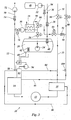
- the injection system from FIG. 3 differs from that in FIG. 2 essentially through a modified fuel recirculation system as well by a pressure control valve 82 for controlling the input pressure of the injection pump 14.
- the pressure control valve 82 is connected through a control line 84 the return line 32 connected so that excess fuel in the Return line 32 can be returned. It always ensures that only liquid fuel, in particular liquid medium pressure fuel to the injection pump 14 arrives.
- Another control line 86 branches from the injection pump supply line 22 and connects them to the high pressure regulator 16. Through this control line 86, a control piston of the high-pressure regulator 16 When operating with medium-pressure fuel, a pressure is applied that increases added to an already existing spring tension of the piston, so that the desired injection pressure can be achieved.
- the return line 46 emanating from the injection pump 14 runs in this Case directly to the low-pressure fuel source, not shown, the return flow as with the return line 78 through a solenoid valve 88 is regulated.
- a branch line 90 with a check valve 92 is the return line 46 with the return line 32 and the filling line 36 connected so that a return to the tank 20 is also possible from here.
- a solenoid valve 93 is arranged, which is another possibility for Control of fuel flow provides.
- throttling of the return flow through the solenoid valve 93 an increase in pressure reach in front of the valve.
- control valve 82 offers a further possibility for temperature and pressure control.
- the electrical Control unit 56 is able, except for the described comparison of temperatures in the tank 20 and in the injection pump supply line 22 and the corresponding Control of the heater 62 to control a pump 94, which serves to a compensation chamber within the control valve 82 with additional pressure apply. This pressure is added to a spring pressure of the control valve in such a way that the necessary fuel pressure can be achieved.
- a branch line 96 is branched off from the injection pump supply line 22, through which a part of the medium pressure fuel contained in the tank 20 branch off as coolant for operating the heat exchanger 28 and again the engine's intake tract.
- the volume flow through this Branch line 96 can be regulated by a further solenoid valve 98.
- the temperature and thus the pressure immediately before the injection pump 14 can be control by regulating the cooling capacity of the heat exchanger 28 accordingly becomes. This can be done by an appropriate connection to the temperature sensor 58, 60 or the control unit 56 happen.
- the injection system shown in FIG. 3 has a further additional feature 10 a sensor 100 in the return line 46 through which the possibility is given the power of the fuel pump 72 and possibly the valves in the return lines 32, 46, 78 in response to a signal to control the sensor 100.
- the measured size is for example the pressure or the fuel mass flow rate per unit of time.
Abstract
Description
Die Erfindung betrifft ein Kraftstoff-Einspritzsystem für Brennkraftmaschinen gemäß dem Oberbegriff des Anspruchs 1.The invention relates to a fuel injection system for internal combustion engines according to the preamble of claim 1.
Einspritzsysteme, welche den Kraftstoff in flüssiger Form unmittelbar in den Brennraum einer Brennkraftmaschine einspritzen, sind seit längerer Zeit bekannt und werden beispielsweise im Zusammenhang mit der Common-Rail-Technologie verwendet. Durch die Direkteinspritzung läßt sich eine hohe Leistungsausbeute erzielen, während gleichzeitig der Kraftstoffverbrauch relativ gering ist. Aus diesen Gründen hat diese Technik bereits weite Verbreitung beim Bau von Kraftfahrzeug-Motoren gefunden.Injection systems, which direct the fuel in liquid form into the Injecting the combustion chamber of an internal combustion engine has been known for a long time and are used, for example, in connection with common rail technology used. The direct injection enables a high power yield achieve while keeping fuel consumption relatively low is. For these reasons, this technology is already widely used in the Construction of motor vehicle engines found.
Seit einiger Zeit besteht das Bedürfnis, neben den bisher üblichen flüssigen Kraftstoffen wie Benzin oder Diesel weitere Kraftstoffquellen zu erschließen. Zum Betrieb von Fahrzeugmotoren kommt insbesondere Flüssiggas in Betracht, das als Nebenprodukt bei der Herstellung von Benzin und Diesel anfällt. Es läßt sich mit guter Leistungsausbeute zum Betrieb von Verbrennungsmotoren verwenden und führt zu geringeren Umweltemissionen. Üblicherweise handelt es sich hierbei um ein Propan-Butan-Gemisch, welches auch als LPG (Liquified-Petroleum-Gas) bezeichnet wird. Unter Atmosphärendruck ist dieser Kraftstoff gasförmig, läßt sich jedoch durch Beaufschlagung eines relativ geringen Überdrucks von ca. 6 bar im flüssigen Aggregatzustand halten. Diese Art von Kraftstoff soll daher im folgenden als Mitteldruckkraftstoff bezeichnet werden, in Abgrenzung zu den bei Atmosphärendruck flüssigen Niederdruckkraftstoffen wie Benzin oder Diesel. Grundsätzlich läßt sich auch Mitteldruckkraftstoff in dem oben beschriebenen Direkteinspritzsystem verwenden, vorausgesetzt, daß der Kraftstoff unter Druck und somit flüssig gehalten wird und in diesem Zustand in die Brennkammer eingespritzt werden kann.For some time there has been a need, in addition to the liquid that has been customary up to now Fuels such as gasoline or diesel to tap additional fuel sources. To the Operation of vehicle engines is particularly suitable for liquefied petroleum gas is a by-product of the manufacture of petrol and diesel. It can be use with good performance to operate internal combustion engines and leads to lower environmental emissions. This is usually the case a propane-butane mixture, which is also known as LPG (liquefied petroleum gas) referred to as. At atmospheric pressure, this fuel is gaseous, can, however, by applying a relatively low excess pressure of Keep approx. 6 bar in the liquid state. This type of fuel is said to be hereinafter referred to as medium pressure fuel, in delimitation to low-pressure fuels such as gasoline or liquid at atmospheric pressure Diesel. Basically, medium pressure fuel can also be used in the above Use direct injection system provided the fuel is under Pressure and thus fluid is kept and in this state in the combustion chamber can be injected.
Geeignete Kraftstoff-Einspritzsysteme sind bereits in unterschiedlichen Varianten bekannt. Beispielsweise zeigt die Druckschrift EP 0 725 208 B1 ein Einspritzsystem, bei welchem Flüssiggas aus einem mit Druck beaufschlagten Speichertank in flüssiger Form der Einspritzpumpe zugeführt wird. Zu diesem Zweck ist innerhalb des Tanks eine Kraftstoffpumpe angeordnet, die das Flüssiggas in die Einspritzpumpen-Zuleitung fördert. Auch die US-A 5 291 869 offenbart ein Flüssiggas-Einspritzsystem mit einer im Tank angeordneten Pumpe. Suitable fuel injection systems are already available in different versions known. For example, the document EP 0 725 208 B1 shows an injection system, at which liquid gas from a pressurized storage tank is supplied in liquid form to the injection pump. To this For this purpose, a fuel pump is arranged inside the tank, which is the liquid gas promotes in the injection pump supply line. US-A 5 291 869 also discloses a liquid gas injection system with a pump arranged in the tank.
Diese Aufbauten bietet den Vorteil, daß sie konstruktiv einfach und preiswert sind.This structure has the advantage that it is structurally simple and inexpensive are.
Bei diesen Systemen tritt jedoch häufig das Problem auf, daß das in flüssiger Form aus dem Tank beförderte Gas sich aufgrund seines niedrigen Dampfdrucks auf dem Weg zur Einspritzpumpe erwärmt und verdampft. Dies ist jedoch höchst unerwünscht, da sich die volle Leistungsausbeute der Brennkraftmaschine nur dann erreichen läßt, wenn der Kraftstoff in flüssiger Form eingespritzt werden kann. Aus diesem Grund schlägt beispielsweise die erwähnte USA 5 291 869 ein Kühlsystem vor, durch welches der Kraftstoff unmittelbar vor dem Einspritzen gekühlt wird, so daß er im flüssigen Aggregatzustand verbleibt.However, the problem often arises with these systems that it is in a liquid state Form from the tank transported gas due to its low vapor pressure warmed and evaporated on the way to the injection pump. However, this is highly undesirable, since the full performance of the engine can only be achieved if the fuel is injected in liquid form can be. For this reason, for example, the USA mentioned beats 5 291 869 a cooling system through which the fuel immediately before the injection is cooled so that it remains in the liquid state.
Damit die Verflüssigung durch ein solches Kühlsystem effektiv durchgeführt werden kann, ist eine relativ aurwendige Konstruktion erforderlich, damit eine ausreichende Kühlleistung zur Verfügung gestellt werden kann. Insbesondere muß die Einspritzpumpe selbst stark modifiziert werden. Es kommt daher grundsätzlich die alternative Möglichkeit in Betracht, den Mitteldruckkraftstoff durch die Pumpe im Tank mit einem Druck zu beaufschlagen, der ausreichend ist, um den Kraftstoff über die gesamte Einspritzpumpen-Zuleitung hinweg flüssig zu halten. Da der erzeugte Druck sehr hoch sein muß, ist eine hohe Pumpenleistung erforderlich. Die Anbringung einer derart leistungsfähigen Pumpe in einem Flüssiggas-Tank führt jedoch aus Platzgründen und aufgrund ihrer höheren Betriebstemperatur zu weiteren Problemen bei der Konstruktion und beim Betrieb des Einspritzsystems. Bei vergleichsweise langen Einspritzpumpen-Zuleitungen sind die Einsatzmöglichkeiten dieses Aufbaus jedoch begrenzt, da der aufzubringende Druck mit der Leitungslänge ansteigt. Zudem muß das gesamte Leitungssystem so druckfest ausgelegt sein, daß es dem gegenüber den herkömmlichen Systemen höheren Betriebsdruck standhält.So that the liquefaction is effectively carried out by such a cooling system a relatively complex construction is required so that a sufficient cooling capacity can be provided. In particular the injection pump itself must be heavily modified. It comes from that basically consider the alternative option, the medium pressure fuel to be pressurized by the pump in the tank with sufficient pressure is liquid to the fuel over the entire injection pump supply line to keep. Since the pressure generated must be very high, there is a high pump output required. The installation of such a powerful pump in A liquefied petroleum gas tank, however, runs out of space and because of its higher Operating temperature to further problems in construction and Operation of the injection system. With comparatively long injection pump supply lines the possible uses of this structure are limited, however, because of the pressure to be applied increases with the line length. In addition, the entire Pipe system designed so that it is pressure-resistant compared to conventional Systems withstands higher operating pressures.
Aufgabe der vorliegenden Erfindung ist es daher, ein Kraftstoff-Einspritzsystem der eingangs genannten Art zu schaffen, durch welches sich Mitteldruckkraftstoff in flüssiger Form der Einspritzpumpe zuführen läßt, ohne daß der konstruktive Aufwand gegenüber den bekannten Systemen wesentlich ansteigt und ohne daß Probleme beim Betrieb auftreten.The object of the present invention is therefore a fuel injection system to create the type mentioned, through which medium-pressure fuel can be supplied in liquid form to the injection pump without the constructive Effort increases significantly compared to the known systems and without operating problems.
Diese Aufgabe wird erfindungsgemäß durch ein Kraftstoff-Einspritzsystem mit den Merkmalen des Anspruchs 1 gelöst. This object is achieved by a fuel injection system solved the features of claim 1.
Bei dem erfindungsgemäßen Kraftstoff-Einspritzsystem ist zusätzlich zu der im Tank angeordneten Kraftstoffpumpe eine weitere, zweite Kraftstoffpumpe stromabwärts in der Einspritzpumpen-Zuleitung außerhalb des Tanks angeordnet. Diese beiden Pumpen sind also in Reihe geschaltet, so daß sich die von ihnen erzeugten Drücke addieren. Die Pumpe im Tank sorgt dafür, daß der Mitteldruckkraftstoff den Tank in flüssiger Form verläßt und auch noch in diesem Zustand die zweite Pumpe erreicht. Diese beugt dann durch die zusätzliche Druckbeaufschlagung einem weiteren Druckabfall vor, so daß gewährleistet wird, daß der Einspritzpumpe stets nur flüssiger Kraftstoff zugeführt wird.In the fuel injection system according to the invention is in addition to the Tank arranged fuel pump another, second fuel pump downstream arranged in the injection pump supply line outside the tank. So these two pumps are connected in series so that they are different add generated pressures. The pump in the tank ensures that the medium pressure fuel leaves the tank in liquid form and still in this state reached the second pump. This then bends through the additional pressurization another pressure drop before, so that it is ensured that only liquid fuel is supplied to the injection pump.
Diese Konstruktion ist insofern relativ einfach, als daß keine Veränderung der Einspritzpumpe notwendig ist, sondern lediglich eine Flüssigkraftstoff-Pumpe zusätzlich in die Einspritzpumpen-Zuleitung eingebaut werden muß. Die Leistung der Pumpe im Tank kann so weit begrenzt sein, daß sie gerade ausreicht, um den Kraftstoff bis zum Erreichen der zweiten Pumpe flüssig zu halten. Zu diesem Zweck genügt auch eine klein dimensionierte Kraftstoffpumpe, so daß es keine Probleme bei der Unterbringung und in Bezug auf die Abwärme gibt. Schließlich kann der Teil der Einspritzpumpen-Zuleitung zwischen der ersten und der zweiten Kraftstoffpumpe auf einen vergleichsweise niedrigen Nenndruck ausgelegt sein, unabhängig von dem höheren Enddruck, der durch die zweite Pumpe erzeugt wird.This construction is relatively simple in that no change in the Injection pump is necessary, but only a liquid fuel pump must also be installed in the injection pump supply line. The performance the pump in the tank can be so limited that it is just sufficient to keep the fuel liquid until the second pump is reached. To a small-sized fuel pump is sufficient for this purpose, so that it there are no problems with accommodation and with regard to waste heat. Finally, the part of the injection pump supply line can be between the first and the second fuel pump to a comparatively low nominal pressure be designed regardless of the higher ultimate pressure caused by the second Pump is generated.
Vorzugsweise handelt es sich bei dem Mitteldruckkraftstoff um Flüssiggas (LPG). In bevorzugten Ausführungsformen umfaßt das erfindungsgemäße Kraftstoff-Einspritzsystem ein Hochdruckventil zur Steuerung des Einspritzdruckes der Einspritzpumpe sowie ein Drucksteuerventil zur Steuerung des Druckes in der Einspritzpumpen-Zuleitung.The medium-pressure fuel is preferably liquefied petroleum gas (LPG). In preferred embodiments, the fuel injection system according to the invention comprises a high pressure valve to control the injection pressure of the Injection pump and a pressure control valve to control the pressure in the Injection pump supply line.
In einer weiteren bevorzugten Ausführungsform mündet in die Einspritzpumpen-Zuleitung eine Niederdruckkraftstoff-Zuleitung zum Einspeisen eines unter Atmosphärendruck flüssigen Niederdruckkraftstoffs aus einer Niederdruckkraftstoff-Quelle, und die Niederdruckkraftstoff-Zuleitung und die Einspritzpumpen-Zuleitung umfassen Einrichtungen zum Umschalten zwischen einer Kraftstoffzufuhr aus der Niederdruckkraftstoff-Quelle und einer Kraftstoffzufuhr aus dem Tank. In a further preferred embodiment, the injection pump feed line opens a low pressure fuel supply line for feeding one under Atmospheric pressure liquid low pressure fuel from a low pressure fuel source, and the low pressure fuel supply line and the injection pump supply line include means for switching between a fuel supply from the low pressure fuel source and a fuel supply from the Tank.
Bei dieser Ausführungsform handelt es sich um ein sogenanntes bivalentes System, das sowohl mit Niederdruck-Kraftstoff als auch mit Mitteldruckkraftstoff zu betreiben ist und aufgrund dieser Wahlmöglichkeit besonders flexibel einsetzbar ist. Hierbei ist die Einspritzpumpe dazu vorgesehen, entweder Niederdruckkraftstoff wie etwa Benzin oder Diesel oder flüssigen Mitteldruckkraftstoff in den Brennraum der Brennkraftmaschine einzuspritzen, ohne daß Modifikationen oder Ergänzugen der Einspritzpumpe gegenüber einem herkömmlichen Niederdruckkraftstoff-System erfoderlich sind. Durch entsprechende Umschalteinrichtungen ist eine Wahl zwischen den beiden Betriebsarten möglich. Diese können insbesondere dazu dienen, mit unterschiedlichen Drücken beaufschlagte Teile des Systems voneinander zu trennen und beispielsweise zu verhindern, daß der zur Einspeisung von Niederdruckkraftstoff dienende Systembereich mit dem Druck beaufschlagt wird, der in dem Systembereich herrscht, aus welchen der Mitteldruckkraftstoff eingespeist wird. Im umgekehrten Fall ist zu verhindern, daß der Druck in der Mitteldruckkraftstoff-Zufuhr so weit abfällt, daß es in der Kraftstoffleitung zu dem unerwünschten Verdampfen des Mitteldruckkraftstoffs kommt.This embodiment is a so-called bivalent system, both with low-pressure fuel and with medium-pressure fuel is to be operated and can be used particularly flexibly due to this option is. The injection pump is provided for this purpose, either low-pressure fuel such as gasoline or diesel or liquid medium pressure fuel in the Inject the combustion chamber of the internal combustion engine without modifications or supplementing the injection pump compared to a conventional low-pressure fuel system are required. With appropriate switching devices you can choose between the two operating modes. these can in particular serve to act on parts with different pressures to separate the system from one another and, for example, to prevent the system area for feeding in low pressure fuel with the Pressure is applied that prevails in the system area from which the Medium pressure fuel is fed. In the opposite case, prevent that the pressure in the medium pressure fuel supply drops so far that it is in the Fuel line to the undesirable vaporization of the medium pressure fuel comes.
Vorzugsweise mündet die Niederdruckkraftstoff-Zuleitung an einem Punkt stromabwärts der zweiten Kraftstoffpumpe in die Einspritzpumpen-Zuleitung, so daß beide oben erwähnten Kraftstoffpumpen dazu dienen, lediglich die Mitteldruckkraftstoff-Komponente zu fördern und mit Druck zu beaufschlagen. Die Umschalt-Einrichtungen umfassen bevorzugt Magnetventile zum Zu- oder Abschalten der Kraftstoffzufuhr aus dem Tank oder der Niederdruckkraftstoff-Quelle.The low-pressure fuel feed line preferably opens at one point downstream of the second fuel pump into the injection pump feed line, see above that both fuel pumps mentioned above serve only the medium pressure fuel component to promote and apply pressure. The Switching devices preferably include solenoid valves for switching on or off the fuel supply from the tank or the low pressure fuel source.
In einer bevorzugten Ausführungsform ist in der Niederdruckkraftstoff-Zuleitung eine Niederdruckkraftstoff-Pumpe angeordnet, die den Niederdruckkraftstoff selbständig in die Einspritzpumpen-Zuleitung befördern kann. Die Niederdruckkraftstoff-Pumpe und die in Serie geschalteten Mitteldruckkraftstoff-Pumpen sind unabhängig voneinander betreibbar. Dies erweist sich zur Kontrolle der Druckverhältnisse bei Umschaltvorgängen als vorteilhaft. Wird beispielsweise von Mitteldruckkraftstoff auf Niederdruckkraftstoff umgeschaltet, so ist es möglich, die Mitteldruckkraftstoff-Pumpen abzuschalten, während die Niederdruckkraftstoff-Pumpe den Druck in der Einspritzpumpen-Zuleitung aufrechterhält. Die in der Zuleitung verbleibenden Mitteldruckkraftstoff-Reste werden dadurch am Verdampfen gehindert und können der Einspritzpumpe in flüssiger Form zugeführt werden, während sie allmählich vom Niederdruckkraftstoff verdrängt werden. Dies trägt dazu bei, das Auftreten unerwünschter gasförmiger Kraftstoff-Komponenten bei Umschaltvorgängen vollständig zu verhindern, so daß keine Betriebs- oder Leistungsstörungen auftreten und eine kontinuierliche Verbrennung möglich ist.In a preferred embodiment is in the low pressure fuel supply line a low pressure fuel pump is arranged which is the low pressure fuel can independently convey into the injection pump supply line. The low pressure fuel pump and the series-connected medium pressure fuel pumps can be operated independently of each other. This turns out to control the Pressure ratios in switching operations as advantageous. For example switched from medium pressure fuel to low pressure fuel, so it is possible turn off the medium pressure fuel pumps while the low pressure fuel pump maintains the pressure in the injection pump supply line. The medium pressure fuel residues remaining in the supply line are thereby prevented from evaporation and can be fed to the injection pump in liquid form as they are gradually displaced by low pressure fuel become. This helps prevent the occurrence of unwanted gaseous fuel components to prevent completely during switching operations, so that there are no operational or performance disruptions and continuous combustion is possible.
Weitere vorteilhafte Ausgestaltungen der Erfindung ergeben sich aus den übrigen Unteransprüchen.Further advantageous refinements of the invention result from the others Dependent claims.
Im folgenden werden bevorzugte Ausführungsbeispiele der Erfindung anhand der Zeichnung näher erläutert.
- Fig. 1
- ist ein Schaltbild eines ersten Ausführungsbeispiels eines erfindungsgemäßen Kraftstoff-Einspritzsystems;
- Fig. 2
- ist ein Schaltbild eines zweiten Ausführungsbeispiels eines erfindungsgemäßen Kraftstoff-Einspritzsystems; und
- Fig. 3
- ist ein Schaltbild entsprechend Figur 2 einer zweiten Ausführungsform eines erfindungsgemäßen Kraftstoff-Einspritzsystems.
- Fig. 1
- is a circuit diagram of a first embodiment of a fuel injection system according to the invention;
- Fig. 2
- is a circuit diagram of a second embodiment of a fuel injection system according to the invention; and
- Fig. 3
- is a circuit diagram corresponding to Figure 2 of a second embodiment of a fuel injection system according to the invention.
Bei dem in Fig. 1 dargestellten Kraftstoff-Einspritzsystem 10 handelt es sich um
ein Einspritzsystem, das zum Betrieb mit einem Mitteldruckkraftstoff geeignet
ist, der unter Atmosphärendruck gasförmig ist und zur Verflüssigung mit einem
Druck von zumindest etwa 6 bar beaufschlagt werden muß. Hierbei kann es
sich insbesondere um Flüssiggas handeln, welches auch als LPG (Liquified Petroleum
Gas) bezeichnet wird und ein Propan-Butan-Gemisch ist.The
Das Einspritzssystem 10 ist nach dem Common-Rail-Prinzip aufgebaut, d.h.,
durch ein in Figur 1 nur schematisch dargestelltes Verteilerrohr 12 wird der
nicht gezeigte Brennraum eines Motors mit Kraftstoff versorgt. Dies geschieht
unter hohem Druck durch eine Einspritzpumpe 14, die den mit Druck beaufschlagtem
Kraftstoff in das Verteilerrohr eingespeist. Über einen Hochdruckregler
16, der an das Verteilerrohr 12 angeschlossen ist, kann überschüssiger,
nicht dem Brennraum zugeführter Kraftstoff abgeleitet werden. Gleichzeitig
dient der Hochdruckregler 16 dazu, den Druck im Verteilerrohr 12 zu regeln. The
In einem Tank 20 ist Mitteldruckkraftstoff unter einem Druck gespeichert, der
höher ist als der Verdampfungsdruck des Mitteldruckkraftstoffs. Beispielsweise
beträgt der Druck innerhalb des Tanks 20 25 bar, während der Abblasdruck der
Tanks 20 bei 30 bar liegt. Der Mitteldruckkraftstoff wird der Einspritzpumpe 14
durch eine Einspritzpumpen-Zuleitung 22 auf die im folgenden erläuterte Weise
zugeführt.Medium pressure fuel is stored in a
Innerhalb des Tanks ist eine erste Kraftstoffpumpe 24 angeordnet, die den flüssig
gehaltenen Mitteldruckkraftstoff in die Einspritzpumpen-Zuleitung 22 einspeist.
Im vorliegenden Fall handelt es sich um eine Tauchpumpe. Die Kraftstoffpumpe
24 kann ferner von der Decke des Tanks 20 abgehängt sein. Der
Mitteldruckkraftstoff passiert in dem außerhalb des Tanks 20 verlaufenden Abschnitt
der Einspritzpumpen-Zuleitung 22 nacheinander ein Magnetventil 26,
einen Wärmetauscher 28 und eine zweite Kraftstoffpumpe 30. Die beiden Kraftstoffpumpen
24, 30 sind somit hintereinander geschaltet, so daß sich ihre Drükke
addieren. Die Leistung der ersten Kraftstoffpumpe 24 ist so bemessen, daß
sie den Mitteldruckkraftstoff mit einem Druck zu beaufschlagt, der ausreichend
ist, um den Mitteldruckkraftstoff auf seinem Weg bis zur zweiten Kraftstoffpumpe
30 flüssig zu halten. Dies wird durch die Kühlleistung des Wärmetauschers
28 unterstützt, welcher durch die Verdampfungskälte von Mitteldruckkraftstoff
betrieben werden kann, der auf hier nicht dargestellte Weise aus dem Tank 20
abgezweigt wird. Wahlweise ist es möglich, als Kühlmittel des Wärmetauschers
28 das Kältemittel einer Klimaanlage des Fahrzeugs zu verwenden.A
Die zweite Kraftstoffpumpe 30 beaufschlagt den Mitteldruckkraftstoff mit einem
zusätzlichen Druck, der ausreicht, um der Kraftstoff der Einspritzpumpe 14 in
flüssiger Form zuzuführen. Das Magnetventil 26 dient dazu, die Kraftstoffzufuhr
gegebenenfalls vollständig abzuschalten und somit den Betrieb der Brennkraftmaschine
zu unterbrechen.The
Durch die serielle Anordnung der Kraftstoffpumpen 24, 30 läßt sich gewährleisten,
daß stets nur flüssiger Mitteldruckkraftstoff zur Einspritzpumpe 14 gelangt.
Da dieser nun in flüssiger Form in den Brennraum eingespritzt wird, wird
keine Ansaugluft mehr verdrängt. Dadurch erhöht sich der Füllungsgrad der Zylinder
im Vergleich zur Einspritzung in den Ansaugtrakt und damit auch die
Leistung des Motors. The serial arrangement of the fuel pumps 24, 30 can ensure
that only liquid medium pressure fuel always reaches the
Eine Rücklaufleitung 32 dient dazu, überschüssigen, nicht in den Brennraum
eingespritzten Kraftstoff vom Hochdruckregler 16 wahlweise in die Einspritzpumpen-Zuleitung
22 oder in den Tank 20 zurückzuführen. Zu diesem Zweck
ist die Rücklaufleitung 32 einerseits über eine Querverbindung 34 mit der Einspritzpumpen-Zuleitung
22 verbunden und mündet andererseits selbst in eine
Fülleitung 36, die zum Befüllen des Tanks 20 dient und in diesen hineinführt.
Über die Fülleitung 36 kann ferner Mitteldruckkraftstoff aus einer nicht dargestellten
Mitteldruckkraftstoff-Quelle in den Tank gefüllt werden. Um einen Rückstrom
zur Mitteldruckkraftstoff-Quelle zu verhindern, ist in der Fülleitung 36 ein
Rückschlagventil 38 angeordnet. Ein weiteres Rückschlagventil 40 am Einlaß
zum Tank 20 sorgt dafür, daß der Druck im Tank 20 aufrecht erhalten bleibt.
Ferner sind in der Rücklaufleitung 32 und in der Querverbindung 34 Magnetventile
42, 44 angeordnet, durch welche sich der Durchfluß steuern läßt. Eine
weitere Rücklaufleitung 46 führt Kraftstoff von der Einspritzpumpe 14 in die
Rücklaufleitung 32. Schließlich besteht die Möglichkeit, aus einem Schmiermittel-Tank
48 ein Schmiermittel über die Fülleitung 36 in den Tank 20 einzuspeisen
und dieses somit unter den Mitteldruckkraftstoff zu mischen, welches die
Betriebseigenschaften des Kraftstoffs verbessern kann. Hierzu ist der Schmiermittel-Tank
48 über eine entsprechende Zuleitung 50 mit einer Schmiermittel-Pumpe
52 und einem Rückschlagventil 54 zur Verhinderung eines Rückstroms
mit der Fülleitung 36 verbunden.A
Die vorliegende Anordnung bietet ferner Möglichkeiten zur Temperatur- und
Drucksteuerung. Zu diesem Zweck ist eine elektrische Steuereinheit 56 vorgesehen,
die mit zwei Temperaturfühlern verbunden ist, nämlich einem ersten Temperaturfühler
58 in der Einspritzpumpen-Zuleitung am Eingang der Einspritzpumpe
14 und einem zweiten Temperaturfühler 60 zur Messung der Temperatur
innerhalb des Tanks 20. Die Steuereinheit 56 ist somit in der Lage, die Temperatur
im Tank 20 mit derjenigen in der Einspritzpumpen-Zuleitung 22 unmittelbar
vor der Einspritzpumpe 14 zu vergleichen. Außerdem befindet sich im Tank
20 eine elektrische Heizung 62, die durch die elektrische Steuereinheit 46 gesteuert
werden kann. Alternativ können an der Außenseite des Tanks 20 Heizmatten
angebracht sein, oder es wird die Kühlflüssigkeit des Kühlers der Brennkraftmaschine,
die durch deren Abwärme erhitzt ist, zum Heizen verwendet. Zur
Umgebung hin kann der Tank 20 wärmeisoliert sein und/oder eine Schallisolation
aufweisen. The present arrangement also offers possibilities for temperature and
Pressure control. An
Der Vergleich der Temperaturen im Tank 20 und in der Einspritzpumpen-Zuleitung
22 bietet im Zusammenhang mit der elektrischen Heizung 62 die Möglichkeit.
Temperaturschwankungen im System besser abzufangen. Insbesondere ist
es notwendig, Temperaturspitzen auszugleichen, die durch Wärmeleitung innerhalb
des Systems und durch die Wärmeabstrahlung der Brennkraftmaschine
verursacht werden. Es muß jedoch gewährleistet sein, daß der herrschende
Druck des Mitteldruckkraftstoffs am Eingang der Einspritzpumpe 14 immer höher
ist als sein Dampfdruck. Die Steuereinheit 56 vergleicht somit die Temperaturen
im Tank 20 und am Eingang der Einspritzpumpe 14 und reagiert, falls die
Differenz der Meßwerte einen vorgegebenen Wert überschreitet, mit einem Zuschalten
der elektrischen Heizung 62. Auf diese Weise kann sichergestellt werden,
daß eine bestimmte maximale Temperaturdifferenz nicht überschritten
wird. Wird diese unterschritten, so kann die Heizleistung der Heizung 62 abgeschaltet
werden.The comparison of the temperatures in the
Figur 2 zeigt eine Abwandlung des erfindungsgemäßen Einspritzsystems 10 aus
Figur 1. Zur besseren Verständlichkeit sind in den Figuren 1 und 2 gleiche Teile
mit identischen Bezugszeichen versehen.FIG. 2 shows a modification of the
Die Anordnung der Einspritzpumpen-Zuleitung 22 zur Förderung von Mitteldruckkraftstoff
aus dem Tank 20 zur Einspritzpumpe 14 entspricht im wesentlichen
Figur 1, insbesondere die Anordnung der ersten Kraftstoffpumpe 24 im
Tank 20, der nachgeschalteten zweiten Kraftstoffpumpe 30 sowie des dazwischen
angeordneten Wärmetauschers 28.The arrangement of the injection
Abweichend von Figur 1 umfaßt die Anordnung aus Figur 2 zusätzlich eine Niederdruckkraftstoff-Zuleitung
70, die an einem Punkt stromabwärts der zweiten
Kraftstoffpumpe 30 in die Einspritzpumpen-Zuleitung 22 mündet. Durch diese
läßt sich aus einer nicht dargestellten Quelle Niederdruckkraftstoff in die Einspritzpumpen-Zuleitung
22 einspeisen. Bei diesem handelt es sich um einen unter
Atmosphärendruck flüssigen Kraftstoff wie etwa Diesel oder Benzin oder gegebenenfalls
auch Pflanzenöl. Durch geeignete Zuführungs- und Umschalteinrichtungen,
die im folgenden erläutert werden sollen, läßt sich somit wahlweise
flüssiger Niederdruckkraftstoff oder Mitteldruckkraftstoff der Einspritzpumpe 14
zuführen. In a departure from FIG. 1, the arrangement from FIG. 2 additionally comprises a low-pressure
Die Niederdruckkraftstoff-Zuleitung 70 umfaßt ebenfalls eine Kraftstoffpumpe
72 zum Fördern des Niederdruckkraftstoffs in die Einspritzpumpen-Zuleitung
22. Stromabwärts dieser Niederdruckkraftstoff-Pumpe 72 ist ein Rückschlagventil
74 angeordnet, welches einen Rückstrom entlang der Niederdruckkraftstoff-Zuleitung
70 verhindert. Stromaufwärts der Niederdruckkraftstoff-Pumpe 72
kann auf nicht dargestellte Weise eine Förderpumpe zur Beförderung von Niederdruckkraftstoff
aus einem Tank angeordnet sein, so daß die nachgeschaltete
Niederdruckkraftstoff-Pumpe 72 vor allem dazu dient, den geförderten Niederdruckkraftstoff
mit einem ausreichenden Druck zu beaufschlagen.The low pressure
Durch welchselweises Betreiben der Kraftstoffpumpen 24 und 30 sowie 72 in
den jeweiligen Leitungen 22, 70 sowie durch Öffnen oder Schließen entsprechender
Magnetventile läßt sich also wahlweise die eine oder die andere Kraftstoff-Komponente
der Einspritzpumpe 14 zuführen. Wird vom Betrieb mit Mitteldruckkraftstoff
auf Niederdruckkraftstoff umgeschaltet, so wird ein zwischen der
Mitteldruckkraftstoff-Pumpe 30 und der Einmündung der Niederdruckkraftstoff-Zuleitung
70 gelegenes zusätzliches Magnetventil 76 sowie das Magnetventil 26
geschlossen, die Mitteldruckkraftstoff-Pumpen 24, 30 werden abgeschaltet, und
die Niederdruckkraftstoff-Pumpe 72 hält das Druckniveau im System aufrecht,
damit in den Leitungen 22, 70 verbliebene Reste von Mitteldruckkraftstoff nicht
verdampfen können. Auf diese Weise wird ein reibungsloser und störungsfreier
Betrieb der Einspritzpumpe 14 gewährleistet, da der Einspritzpumpe 14 stets
nur flüssiger Kraftstoff zugeführt wird.By alternately operating the fuel pumps 24 and 30 and 72 in
the
Das Einspritzssystem aus Figur 2 umfaßt ferner ein Kraftstoff-Rückführungssystem
entsprechend Figur 1. Ergänzend zweigt von der Rücklaufleitung 32 eine
weitere Rücklaufleitung 78 ab, die zur Niederdruckkraftstoff-Quelle führt und
durch ein Magnetventil 80 geöffnet oder geschlossen werden kann. Das Kraftstoff-Rückführungssystem
aus Figur 2 ermöglicht es insbesondere, Niederdruckkraftstoff
in den Mittelsruckkraftstoff-Tank 20 einzuleiten und auf diese
weise ein Kraftstoff-Gemisch zu erzeugen, falls dies erwünscht ist. Bezüglich der
Funktionen der Temperaturfühler 58, 60 und der Heizung 62 kann auf die Ausführungen
im Zusammenhang mit Figur 1 verwiesen werden.The injection system of Figure 2 also includes a fuel return system
corresponding to FIG. 1. In addition, one branches off from the
Das Einspritzssystem aus Figur 3 unterscheidet sich von demjenigen in Figur 2
im wesentlichen durch ein verändertes Kraftstoff-Rückführungssystem sowie
durch ein Drucksteuerventil 82 zur Steuerung des Eingangsdrucks der Einspritzpumpe
14. Das Drucksteuerventil 82 ist durch eine Steuerleitung 84 mit
der Rücklaufleitung 32 verbunden, so daß überschüssiger Kraftstoff in die
Rücklaufleitung 32 rückgeführt werden kann. Es gewährleistet, daß stets nur
flüssiger Kraftstoff, also insbesondere flüssiger Mitteldruck-Kraftstoff zur Einspritzpumpe
14 gelangt. Eine weitere Steuerleitung 86 zweigt von der Einspritzpumpen-Zuleitung
22 ab und verbindet diese mit dem Hochdruckregler 16.
Durch diese Steuerleitung 86 wird ein Steuerkolben des Hochdruckreglers 16
beim Betrieb mit Mitteldruck-Kraftstoff mit einem Druck beaufschlagt, der sich
zu einer bereits vorhandenen Federspannung des Kolbens addiert, so daß der
gewünschte Einspritzdruck erreicht werden kann.The injection system from FIG. 3 differs from that in FIG. 2
essentially through a modified fuel recirculation system as well
by a
Die von der Einspritzpumpe 14 ausgehende Rücklaufleitung 46 verläuft in diesem
Fall unmittelbar zu der nicht dargestellten Niederdruckkraftstoff-Quelle,
wobei der Rücklaufstrom ebenso wie bei der Rücklaufleitung 78 durch ein Magnetventil
88 geregelt ist. Durch eine Zweigleitung 90 mit einem Rückschlagventil
92 ist die Rücklaufleitung 46 mit der Rücklaufleitung 32 und der Fülleitung
36 verbunden, so daß auch von hier aus ein Rücklauf zum Tank 20 möglich ist.
Ferner ist in der Rücklaufleitung 32 unmittelbar vor der Einmündung in die
Fülleitung 36 ein Magnetventil 93 angeordnet, das eine weitere Möglichkeit zur
Steuerung der Kraftstoffstroms bietet. Insbesondere läßt sich durch eine Drosselung
des Rücklaufstroms durch das Magnetventil 93 eine Erhöhung des Drucks
vor dem Ventil erreichen.The
Die vorliegende Anordnung des Steuerventils 82 bietet eine weitere Möglichkeit
zur Temperatur- und Drucksteuerung. Zu diesem Zweck ist die elektrische
Steuereinheit 56 in der Lage, außer dem beschriebenen Vergleich der Temperaturen
im Tank 20 und in der Einspritzpumpen-Zuleitung 22 und der entsprechenden
Steuerung der Heizung 62 eine Pumpe 94 anzusteuern, die dazu dient,
eine Ausgleichskammer innerhalb des Steuerventils 82 zusätzlich mit Druck zu
beaufschlagen. Dieser Druck addiert sich zu einem Federdruck des Steuerventils
in der Weise, daß der notwendige Kraftstoffdruck erreicht werden kann.The present arrangement of the
Ferner ist von der Einspritzpumpen-Zuleitung 22 eine Zweigleitung 96 abgezweigt,
durch welche sich ein Teil des im Tank 20 enthaltenen Mitteldruckkraftstoffs
als Kühlmittel zum Betrieb des Wärmetauschers 28 abzweigen und wieder
dem Ansaugtrakt des Motors rückführen läßt. Der Volumenstrom durch diese
Zweigleitung 96 ist durch ein weiteres Magnetventil 98 regelbar. Die Temperatur
und somit der Druck unmittelbar vor der Einspritzpumpe 14 lassen sich somit
steuern, indem die Kühlleistung des Wärmetauschers 28 entsprechend geregelt
wird. Dies kann durch einen entsprechenden Anschluß an die Temperaturfühler
58, 60 bzw. die Steuereinheit 56 geschehen.Furthermore, a
Als weiteres zusätzliches Merkmal weist das in Figur 3 gezeigte Einspritzsystem
10 einen Meßfühler 100 in der Rücklaufleitung 46 auf, durch welchen die Möglichkeit
gegeben wird, die Leistung der Kraftstoffpumpe 72 und gegebenenfalls
die Ventile in den Rücklaufleitungen 32, 46, 78 in Abhängigkeit von einem Signal
des Meßfühlers 100 zu steuern. Bei der gemessenen Größe handelt es sich
beispielsweise um den Druck oder den Kraftstoff-Massendurchsatz pro Zeiteinheit.The injection system shown in FIG. 3 has a further additional feature
10 a
Claims (17)
Applications Claiming Priority (6)
| Application Number | Priority Date | Filing Date | Title |
|---|---|---|---|
| DE10146051 | 2001-09-18 | ||
| DE10146051A DE10146051B4 (en) | 2001-01-28 | 2001-09-18 | Fuel direct injection |
| DE20209413U DE20209413U1 (en) | 2002-06-17 | 2002-06-17 | LPG tank |
| DE20209413U | 2002-06-17 | ||
| DE2002130958 DE10230958A1 (en) | 2001-09-18 | 2002-07-10 | Fuel injection system, for an IC motor using LPG fuel, has an additional fuel pump in the fuel line to the injection pump to increase the fuel pressure in the flow from the tank |
| DE10230958 | 2002-07-10 |
Publications (2)
| Publication Number | Publication Date |
|---|---|
| EP1293654A2 true EP1293654A2 (en) | 2003-03-19 |
| EP1293654A3 EP1293654A3 (en) | 2004-02-11 |
Family
ID=27214610
Family Applications (1)
| Application Number | Title | Priority Date | Filing Date |
|---|---|---|---|
| EP02021233A Withdrawn EP1293654A3 (en) | 2001-09-18 | 2002-09-18 | Fuel injection system for an internal combustion engine |
Country Status (1)
| Country | Link |
|---|---|
| EP (1) | EP1293654A3 (en) |
Cited By (5)
| Publication number | Priority date | Publication date | Assignee | Title |
|---|---|---|---|---|
| EP1785618A1 (en) * | 2005-11-13 | 2007-05-16 | Karlheinrich Winkelmann | Fuel cooling system for internal combustion engines |
| US20130098334A1 (en) * | 2010-06-22 | 2013-04-25 | A. Luhmann Gmbh | Fuel Metering Device for an Internal Combustion Engine |
| US9506409B2 (en) | 2011-06-24 | 2016-11-29 | Indopar B.V. | Method of switching from a liquefied gas fuel to a liquid fuel being provided to a direct injection combustion engine, and direct injection bi-fuel system for such an engine |
| CN111677611A (en) * | 2020-06-24 | 2020-09-18 | 天津大学 | Internal combustion engine fuel supercritical injection system and control method |
| DE102012105604B4 (en) * | 2011-12-07 | 2021-05-06 | Hyundai Motor Company | Heat exchanger for a vehicle |
Citations (5)
| Publication number | Priority date | Publication date | Assignee | Title |
|---|---|---|---|---|
| DE19611381A1 (en) * | 1995-03-23 | 1996-09-26 | Avl Verbrennungskraft Messtech | Fuel-injection system for IC engine |
| US5857448A (en) * | 1995-03-23 | 1999-01-12 | AVL Gesellschaft fur Verbrennungskraftmaschinen und Messtechnik m.b.H. Prof.Dr.Dr.h.c. Hans List | Injection system for an internal combustion engine |
| EP1010886A1 (en) * | 1998-12-15 | 2000-06-21 | Renault | Improved fuel injection system |
| JP2001349256A (en) * | 2000-06-06 | 2001-12-21 | Nippon Soken Inc | Fuel supply system of internal combustion engine |
| DE20101475U1 (en) * | 2001-01-28 | 2002-06-13 | Winkelmann Karlheinrich | direct injection |
-
2002
- 2002-09-18 EP EP02021233A patent/EP1293654A3/en not_active Withdrawn
Patent Citations (5)
| Publication number | Priority date | Publication date | Assignee | Title |
|---|---|---|---|---|
| DE19611381A1 (en) * | 1995-03-23 | 1996-09-26 | Avl Verbrennungskraft Messtech | Fuel-injection system for IC engine |
| US5857448A (en) * | 1995-03-23 | 1999-01-12 | AVL Gesellschaft fur Verbrennungskraftmaschinen und Messtechnik m.b.H. Prof.Dr.Dr.h.c. Hans List | Injection system for an internal combustion engine |
| EP1010886A1 (en) * | 1998-12-15 | 2000-06-21 | Renault | Improved fuel injection system |
| JP2001349256A (en) * | 2000-06-06 | 2001-12-21 | Nippon Soken Inc | Fuel supply system of internal combustion engine |
| DE20101475U1 (en) * | 2001-01-28 | 2002-06-13 | Winkelmann Karlheinrich | direct injection |
Non-Patent Citations (1)
| Title |
|---|
| PATENT ABSTRACTS OF JAPAN vol. 2002, no. 04, 4. August 2002 (2002-08-04) -& JP 2001 349256 A (NIPPON SOKEN INC), 21. Dezember 2001 (2001-12-21) * |
Cited By (6)
| Publication number | Priority date | Publication date | Assignee | Title |
|---|---|---|---|---|
| EP1785618A1 (en) * | 2005-11-13 | 2007-05-16 | Karlheinrich Winkelmann | Fuel cooling system for internal combustion engines |
| US20130098334A1 (en) * | 2010-06-22 | 2013-04-25 | A. Luhmann Gmbh | Fuel Metering Device for an Internal Combustion Engine |
| US9506409B2 (en) | 2011-06-24 | 2016-11-29 | Indopar B.V. | Method of switching from a liquefied gas fuel to a liquid fuel being provided to a direct injection combustion engine, and direct injection bi-fuel system for such an engine |
| DE102012105604B4 (en) * | 2011-12-07 | 2021-05-06 | Hyundai Motor Company | Heat exchanger for a vehicle |
| CN111677611A (en) * | 2020-06-24 | 2020-09-18 | 天津大学 | Internal combustion engine fuel supercritical injection system and control method |
| CN111677611B (en) * | 2020-06-24 | 2023-09-12 | 天津大学 | Supercritical fuel injection system of internal combustion engine and control method |
Also Published As
| Publication number | Publication date |
|---|---|
| EP1293654A3 (en) | 2004-02-11 |
Similar Documents
| Publication | Publication Date | Title |
|---|---|---|
| DE602005001546T2 (en) | Arrangement for conveying gaseous fuel to a power generation unit of a ship for the transport of liquefied gas | |
| EP1785618B2 (en) | Fuel cooling system for internal combustion engines | |
| DE10310345A1 (en) | Fuel supply device for a low boiling point fuel and method for its control | |
| DE10146051B4 (en) | Fuel direct injection | |
| DE60309184T2 (en) | FUEL RECYCLING DEVICE FOR INTERNAL COMBUSTION ENGINE | |
| DE102008063566A1 (en) | Gas pressure regulator for conditioning source pressure of supplying gas to consumption pressure, in fuel supply system of motor vehicle, has heating device with heating chamber and electrical heating element that is arranged in chamber | |
| DE102007028816A1 (en) | IC engine with dual fuel including liquid gas with one shared common rail and one set of injector valves | |
| DE102014218632A1 (en) | Fuel supply device, method for operating a fuel supply device and computer program product | |
| DE102010034227A1 (en) | Internal combustion engine, in particular for a motor vehicle | |
| DE102019133796A1 (en) | A HEAT EXCHANGER FOR A WATER INJECTION SYSTEM, A SYSTEM, A CONTROL SYSTEM, A METHOD AND A VEHICLE | |
| WO2017140480A1 (en) | Internal combustion engine and method for operating an internal combustion engine | |
| DE102018221323A1 (en) | Fuel delivery device for an internal combustion engine | |
| EP1293654A2 (en) | Fuel injection system for an internal combustion engine | |
| EP2795085B1 (en) | Method and device for controlling the fuel supply of an internal combustion engine operated with liquefied gas | |
| DE10310147B9 (en) | Method for supplying LPG to an internal combustion engine, fuel supply system and fuel supply unit | |
| EP2024623B1 (en) | Device for a natural gas operated internal combustion engine | |
| WO2016046297A1 (en) | Fuel supply device for a vehicle operated with liquefied or compressed gas, method for operating a fuel supply device and computer program product | |
| WO2019115167A1 (en) | Fuel delivery device for an internal combustion engine | |
| EP1090251B1 (en) | System for providing a consumer with a cryogenic medium | |
| DE19738502A1 (en) | High pressure generation system | |
| WO2016041710A1 (en) | Pressure-relief device for a fuel supply device and fuel supply device | |
| EP3333405B1 (en) | Metering unit for a gas operated combustion engine | |
| DE602004013423T2 (en) | Kraftstoffverteilerkomponent | |
| DE102017217609A1 (en) | Fuel delivery device for an internal combustion engine, and a method for conveying fuel in a fuel delivery device | |
| DE102017222931A1 (en) | Fuel delivery device for an internal combustion engine |
Legal Events
| Date | Code | Title | Description |
|---|---|---|---|
| PUAI | Public reference made under article 153(3) epc to a published international application that has entered the european phase |
Free format text: ORIGINAL CODE: 0009012 |
|
| AK | Designated contracting states |
Kind code of ref document: A2 Designated state(s): AT BE BG CH CY CZ DE DK EE ES FI FR GB GR IE IT LI LU MC NL PT SE SK TR Designated state(s): AT BE BG CH CY CZ DE DK EE ES FI FR GB GR IE IT LI LU MC NL PT SE SK TR |
|
| AX | Request for extension of the european patent |
Extension state: AL LT LV MK RO SI |
|
| PUAL | Search report despatched |
Free format text: ORIGINAL CODE: 0009013 |
|
| AK | Designated contracting states |
Kind code of ref document: A3 Designated state(s): AT BE BG CH CY CZ DE DK EE ES FI FR GB GR IE IT LI LU MC NL PT SE SK TR |
|
| AX | Request for extension of the european patent |
Extension state: AL LT LV MK RO SI |
|
| AKX | Designation fees paid | ||
| REG | Reference to a national code |
Ref country code: DE Ref legal event code: 8566 |
|
| STAA | Information on the status of an ep patent application or granted ep patent |
Free format text: STATUS: THE APPLICATION IS DEEMED TO BE WITHDRAWN |
|
| 18D | Application deemed to be withdrawn |
Effective date: 20040812 |