EP1293274A2 - Vorrichtung zum Ablängen von Draht - Google Patents
Vorrichtung zum Ablängen von Draht Download PDFInfo
- Publication number
- EP1293274A2 EP1293274A2 EP02405772A EP02405772A EP1293274A2 EP 1293274 A2 EP1293274 A2 EP 1293274A2 EP 02405772 A EP02405772 A EP 02405772A EP 02405772 A EP02405772 A EP 02405772A EP 1293274 A2 EP1293274 A2 EP 1293274A2
- Authority
- EP
- European Patent Office
- Prior art keywords
- feed direction
- wire
- lancing
- chisel
- cutting
- Prior art date
- Legal status (The legal status is an assumption and is not a legal conclusion. Google has not performed a legal analysis and makes no representation as to the accuracy of the status listed.)
- Granted
Links
Images
Classifications
-
- B—PERFORMING OPERATIONS; TRANSPORTING
- B21—MECHANICAL METAL-WORKING WITHOUT ESSENTIALLY REMOVING MATERIAL; PUNCHING METAL
- B21F—WORKING OR PROCESSING OF METAL WIRE
- B21F11/00—Cutting wire
- B21F11/005—Cutting wire springs
-
- Y—GENERAL TAGGING OF NEW TECHNOLOGICAL DEVELOPMENTS; GENERAL TAGGING OF CROSS-SECTIONAL TECHNOLOGIES SPANNING OVER SEVERAL SECTIONS OF THE IPC; TECHNICAL SUBJECTS COVERED BY FORMER USPC CROSS-REFERENCE ART COLLECTIONS [XRACs] AND DIGESTS
- Y10—TECHNICAL SUBJECTS COVERED BY FORMER USPC
- Y10T—TECHNICAL SUBJECTS COVERED BY FORMER US CLASSIFICATION
- Y10T83/00—Cutting
- Y10T83/929—Tool or tool with support
- Y10T83/9292—Wire tool
-
- Y—GENERAL TAGGING OF NEW TECHNOLOGICAL DEVELOPMENTS; GENERAL TAGGING OF CROSS-SECTIONAL TECHNOLOGIES SPANNING OVER SEVERAL SECTIONS OF THE IPC; TECHNICAL SUBJECTS COVERED BY FORMER USPC CROSS-REFERENCE ART COLLECTIONS [XRACs] AND DIGESTS
- Y10—TECHNICAL SUBJECTS COVERED BY FORMER USPC
- Y10T—TECHNICAL SUBJECTS COVERED BY FORMER US CLASSIFICATION
- Y10T83/00—Cutting
- Y10T83/929—Tool or tool with support
- Y10T83/9295—Work supported tool [e.g., clicker die]
Definitions
- the invention relates to a cutting device for a wire, in particular a spring wire with a counter-holder having a contact surface for guiding a, in a feed direction having moving wire and a, in a bearing guide, movable against the contact surface, a cutting edge having Stechmeissel.
- Cutting devices of the above type serve for cutting wire, for example Steel wire.
- Possible products are, for example, wire rings, wire springs or the like.
- a disadvantage of this known solution is that due to the linear cut material in the area the cut surface is displaced and this to form one, at least partially over the wire cross-section extending burrs and to a deformation of the wire cross-section as a result of compression. Both burr and deformation limit at least a wire end, the applications of the so-cut wire.
- cutting device is a lancing chisel by a Warehouse management on an elliptical orbit with a feed rate adapted to the feed rate Speed led.
- An advantage of this solution is that the advancing movement of the wire for cutting to length does not have to be stopped.
- a disadvantage of this further known solution is that a control of the bearing guide the cutting chisel adversely affects the economics of the cutting device during manufacture effect.
- the present invention has for its object to provide a cutting device for wire create a burr-free, deformation-free and economical cutting of wire.
- the object is achieved in that the bearing guide moving the Cutting edge allowed in feed direction.
- the cutting edge is fixedly arranged on the lancing chisel.
- the bearing guide preferably allows a translational movement of the lancing chisel in Feed direction to ensure a structurally simple storage management.
- the bearing guide allows a pivoting of the Stechmeissel about an axis of rotation in the feed direction.
- the axis of rotation is preferably at the end region opposite the cutting edge arranged, for example, the axis of rotation extends approximately through the transverse to the feed direction and the feed direction facing away edge of the lancing chisel. This is a pivoting the cutting edge facilitates approximately in the feed direction.
- the axis of rotation is arranged in the region of the piercing chisel facing away from the cutting edge in the feed direction.
- a torque is generated at the piercer by the cutting force, which pivots the piercer with rotational direction in the feed direction about the axis of rotation.
- the penetrated into the wire cutting edge of the lancing tool brings by the pivoting movement in the stationary wire a tensile force in the feed direction.
- the not yet severed cross section of the wire is tapered and torn off by the tensile force in the cutting area.
- the cutting pressure on the wire is minimized and thereby also the deformation of the wire cross-section and a burr formation avoided.
- the bearing guide has a return element and one in the feed direction acting stop shoulder on, the sting chisel at least in the area the cutting edge is biased in the feed direction by the return element and in the starting position is in contact with the stop shoulder.
- This is a safe guide of the lancing chisel in the feed direction.
- the stop shoulder defines the starting position of the lancing chisel.
- the reset element on the one hand a guide of the lancing chisel during the separation process safely and on the other hand, in the starting position, pressing the lancing bit against the stop shoulder.
- the spring force of the return element adjustable trained.
- the lancing chisel is preferably in the starting position perpendicular to the contact surface to to ensure a burr-free cut.
- the lancing tool also inclined by an angle in the starting position.
- the contact surface advantageously has a guide device for guiding the wire on to prevent lateral deflection of the wire during the cutting process.
- the guide device has an opening formed open to the contact surface, in Advancing direction, preferably rounded approximately with the radius of the wire, Guide channel to low by this counter contour when cutting the deformation to keep and to ensure a structurally simple and therefore economical solution.
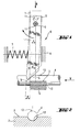
- FIGS. 1 and 2 show a cutting device according to the invention with a piercing chisel 1 and a counter-holder 2, which has a flat contact surface 3 for guiding one, in a feed direction V moving wire 4 has shown.
- a cutting edge 5 having Stechmeissel 1 is characterized by a, generally designated 6 bearing guide, against the Contact surface 3 movably guided.
- the bearing guide 6 has a return element 7 and a stop shoulder 8.
- Fig. 1 is the dashed chisel 1 in the starting position in which he is in Contact with the stop shoulder 8 stands.
- the opposite to the feed direction V of the wire 4 acting return element 7 presses the chisel 1 to the stop shoulder 8.
- the bearing guide 6 has a fastening bolt 3 which can be moved perpendicularly to the contact surface 3 9, which passes through a arranged on the chisel 1 through hole 11.
- the Through hole 11 is preferably on the end face remote from the contact surface 3 of the chisel 1 with a, opposite to the feed direction V extending Distance a from the cutting edge 5 is arranged. Acts a force in a lancing direction S, so causes, perpendicular to the piercing direction S extending distance a pivoting of the lancing chisel 1, in particular the cutting edge 5, with respect to the wire 4.
- the anvil 2 has for the lateral guidance of the wire 4 in the feed direction V, a Guide device on.
- the guide device has a contact surface 3 to open, in the feed direction V extending, semicircular guide channel 12, as can be seen in particular from FIG.
- the Stechmeissel 1 moves first in the lancing direction S and the Movement in the feed direction V of the wire 4 is stopped.
- the lancing chisel 1 against the spring force of the return element 7 in the feed direction V to the formed by the fastening bolt 9 and in a, opposite the feed direction V extending, distance a from the cutting edge 5 about the axis of rotation pivoted. If the wire 4 is severed, the Stechmeissel 1 is back to the starting position moved back.
- the spring force of the return element 7 is adjustable designed.
Landscapes
- Engineering & Computer Science (AREA)
- Mechanical Engineering (AREA)
- Wire Processing (AREA)
- Shearing Machines (AREA)
- Removal Of Insulation Or Armoring From Wires Or Cables (AREA)
- Turning (AREA)
- Electrical Discharge Machining, Electrochemical Machining, And Combined Machining (AREA)
- Harvester Elements (AREA)
Abstract
Description
Bei translatorischer Lagerausführung bewirken beim Ablängvorgang auftretende Kraftkomponenten in Vorschubrichtung, die zur Bildung eines Grats führen würden, das Verschieben der Schneidkante und verhindern somit die Bildung eines Grats. Wesentlich ist, das dadurch zwischen einer Stechrichtung des Stechmeissels und der Schneidkante ein Abstand entsteht, der bei einer Bewegung des Stechmeissel in Stechrichtung als Hebel wirkt und damit zur Schwenkbewegung des Stechmeissels führt.
- Fig. 1
- eine Prinzipdarstellung einer erfindungsgemässen Ablängvorrichtung in der Seitenansicht;
- Fig. 2
- einen vergrösserten Querschnitt des in Fig. 1 dargestellten Gegenhalters
Claims (9)
- Ablängvorrichtung für einen Draht (4), insbesondere einen Federdraht, mit einem Gegenhalter (2), der eine Anlagefläche (3) zur Führung eines, in eine Vorschubrichtung (V) bewegten Drahts (4) aufweist und einem, in einer Lagerführung (6), gegen die Anlagefläche (3) bewegbaren, eine Schneidkante (5) aufweisenden Stechmeissel (1), dadurch gekennzeichnet, dass die Lagerführung (6) ein Bewegen der Schneidkante (5) in Vorschubrichtung (V) erlaubt.
- Ablängvorrichtung nach Anspruch 1, dadurch gekennzeichnet, dass die Lagerführung (6) ein translatorisches Bewegen des Stechmeissels (1) in Vorschubrichtung (V) erlaubt.
- Ablängvorrichtung nach Anspruch 1, dadurch gekennzeichnet, dass die Lagerführung (6) ein Verschwenken des Stechmeissels (1) um eine Drehachse erlaubt.
- Ablängvorrichtung nach Anspruch 1 oder 3, dadurch gekennzeichnet, dass die Drehachse in dem der Schneidkante (5) in Vorschubrichtung (V) abgewandten Bereich des Stechmeissels (1) angeordnet ist.
- Ablängvorrichtung nach Anspruch 4, dadurch gekennzeichnet, dass die Drehachse etwa durch die, quer zur Vorschubrichtung (V) und der Vorschubrichtung (V) abgewandten, Kante des Stechmeissels (1) verläuft.
- Ablängvorrichtung nach einem der Ansprüche 1 bis 5, dadurch gekennzeichnet, dass die Lagerführung für den Stechmeissel (1) ein Rückstellelement (7) und eine in die Vorschubrichtung (V) weisende Anschlagschulter (8) aufweist.
- Ablängvorrichtung nach einem der Ansprüche 1 bis 6, dadurch gekennzeichnet, dass der Stechmeissel (1) in Ausgangsposition senkrecht zur Anlagefläche (3) steht.
- Ablängvorrichtung nach einem der Ansprüche 1 bis 7, dadurch gekennzeichnet, dass die Anlagefläche (3) eine Führungsvorrichtung zur Führung des Drahts (4) quer zur Vorschubrichtung (V) aufweist.
- Ablängvorichtung nach Anspruch 8, dadurch gekennzeichnet, dass die Führungsvorrichtung einen zur Anlagefläche (3) offen ausgebildeten, in Vorschubrichtung (V) verlaufenden, Führungskanal (12) aufweist.
Applications Claiming Priority (2)
| Application Number | Priority Date | Filing Date | Title |
|---|---|---|---|
| DE10145707A DE10145707A1 (de) | 2001-09-17 | 2001-09-17 | Vorrichtung zum Ablängen von Draht |
| DE10145707 | 2001-09-17 |
Publications (3)
| Publication Number | Publication Date |
|---|---|
| EP1293274A2 true EP1293274A2 (de) | 2003-03-19 |
| EP1293274A3 EP1293274A3 (de) | 2003-11-12 |
| EP1293274B1 EP1293274B1 (de) | 2005-05-04 |
Family
ID=7699270
Family Applications (1)
| Application Number | Title | Priority Date | Filing Date |
|---|---|---|---|
| EP02405772A Expired - Lifetime EP1293274B1 (de) | 2001-09-17 | 2002-09-06 | Vorrichtung zum Ablängen von Draht |
Country Status (5)
| Country | Link |
|---|---|
| US (1) | US20030121385A1 (de) |
| EP (1) | EP1293274B1 (de) |
| AT (1) | ATE294652T1 (de) |
| DE (2) | DE10145707A1 (de) |
| ES (1) | ES2240678T3 (de) |
Cited By (2)
| Publication number | Priority date | Publication date | Assignee | Title |
|---|---|---|---|---|
| DE102013207028B3 (de) * | 2013-04-18 | 2014-06-26 | Wafios Ag | Federwindemaschine mit einstellbarer Schnitteinrichtung |
| RU190812U1 (ru) * | 2019-04-15 | 2019-07-12 | Общество с ограниченной ответственностью Управляющая компания "Алтайский завод прецизионных изделий" | Устройство для резки длинномерных материалов |
Families Citing this family (3)
| Publication number | Priority date | Publication date | Assignee | Title |
|---|---|---|---|---|
| DE102010011735B3 (de) * | 2010-03-17 | 2011-07-28 | Wafios AG, 72764 | Anordnung zum Ablängen von Nagelrohlingen von einem intermittierend zugeführten Draht |
| CN105665587A (zh) * | 2016-03-16 | 2016-06-15 | 泰信电机(苏州)有限公司 | 一种新型切线装置 |
| JP6979230B2 (ja) * | 2020-05-08 | 2021-12-08 | 新興機械工業株式会社 | 切断装置、受け部及びホルダ |
Family Cites Families (13)
| Publication number | Priority date | Publication date | Assignee | Title |
|---|---|---|---|---|
| US1892327A (en) * | 1931-12-04 | 1932-12-27 | American Sheet & Tin Plate | Shears |
| US2612912A (en) * | 1948-08-26 | 1952-10-07 | M And B Metal Products Company | Machine for straightening and cutting wire |
| US2697489A (en) * | 1951-10-24 | 1954-12-21 | Continental Foundry & Machine | Severing apparatus for continuously moving material |
| US2696880A (en) * | 1952-10-30 | 1954-12-14 | Gen Electric | Lead wire trimming apparatus |
| US3100414A (en) * | 1961-06-26 | 1963-08-13 | Watkins Ellwood | Oscillating wire cutter |
| DE1915600C2 (de) * | 1969-03-27 | 1984-04-26 | Enka Ag, 5600 Wuppertal | Schneidvorrichtung für Maschinen mit hin- und hergehender Messerbewegung zum Schneiden von Faserkabeln, Folien u.dgl. |
| US3848334A (en) * | 1972-03-24 | 1974-11-19 | J Mattera | Hydraulically actuated cable cutter and indentor |
| GB2112690A (en) * | 1981-12-31 | 1983-07-27 | Sealy | Cut and clench device, and method |
| US4738349A (en) * | 1984-12-18 | 1988-04-19 | The Gillette Company | Automatic spring feeding device |
| DE4040659C1 (en) * | 1990-12-19 | 1992-02-20 | Wafios Maschinenfabrik Gmbh & Co Kg, 7410 Reutlingen, De | Metal spring coiling machine - incorporates wire feed, coiling tools and cutter |
| JP2978075B2 (ja) * | 1994-10-07 | 1999-11-15 | 旭精機工業株式会社 | コイリングマシンのスイングカット式線材切断装置 |
| IT1282392B1 (it) * | 1996-05-02 | 1998-03-20 | Omd Officina Maccanica Domaso | Dispositivo di taglio universale,particolarmente studiato per macchine avvolgitrici per la produzione di molle elicoidali |
| DE19948916A1 (de) * | 1999-10-11 | 2001-04-19 | Tzyh Ru Shyng Automation Co | Antriebsmechanismus zum Bewegen eines Schneidwerkzeugs oder einer Steigungs-Steuerstange in einer Feder-Formmaschine |
-
2001
- 2001-09-17 DE DE10145707A patent/DE10145707A1/de not_active Withdrawn
-
2002
- 2002-09-06 AT AT02405772T patent/ATE294652T1/de active
- 2002-09-06 EP EP02405772A patent/EP1293274B1/de not_active Expired - Lifetime
- 2002-09-06 ES ES02405772T patent/ES2240678T3/es not_active Expired - Lifetime
- 2002-09-06 DE DE50202981T patent/DE50202981D1/de not_active Expired - Lifetime
- 2002-09-13 US US10/243,577 patent/US20030121385A1/en not_active Abandoned
Cited By (2)
| Publication number | Priority date | Publication date | Assignee | Title |
|---|---|---|---|---|
| DE102013207028B3 (de) * | 2013-04-18 | 2014-06-26 | Wafios Ag | Federwindemaschine mit einstellbarer Schnitteinrichtung |
| RU190812U1 (ru) * | 2019-04-15 | 2019-07-12 | Общество с ограниченной ответственностью Управляющая компания "Алтайский завод прецизионных изделий" | Устройство для резки длинномерных материалов |
Also Published As
| Publication number | Publication date |
|---|---|
| DE50202981D1 (de) | 2005-06-09 |
| DE10145707A1 (de) | 2003-04-03 |
| EP1293274A3 (de) | 2003-11-12 |
| ATE294652T1 (de) | 2005-05-15 |
| US20030121385A1 (en) | 2003-07-03 |
| ES2240678T3 (es) | 2005-10-16 |
| EP1293274B1 (de) | 2005-05-04 |
Similar Documents
| Publication | Publication Date | Title |
|---|---|---|
| EP1290977B1 (de) | Lanzette für die Blutentnahme | |
| DE3886975T2 (de) | Vorrichtung und Verfahren zum Schweissen von Drähten mittels Ultraschall. | |
| EP3233377B1 (de) | Werkzeug zum befestigen einer spannschelle | |
| AT411819B (de) | Biegewerkzeug und werkzeugaufnahmevorrichtung für ein solches | |
| EP2114599B1 (de) | Ausgewuchtetes ausbohrwerkzeug mit klemmeinrichtung | |
| DE4109796A1 (de) | Einrichtung zum pressen, biegen und/oder stanzen | |
| EP0470354A1 (de) | Bohrer zur Herstellung von zylindrischen Bohrlöchern | |
| DE3528337C2 (de) | ||
| EP1293274B1 (de) | Vorrichtung zum Ablängen von Draht | |
| DE60118425T2 (de) | Stichsägeblattspannvorrichtung | |
| AT502038B1 (de) | Sicherheitseinrichtung für eine abkantpresse und ein lamellenwerkzeug | |
| DE202008002467U1 (de) | Schneidsatz für elektrische Haarschneidemaschinen | |
| DE102018002358A1 (de) | Kniehebelspannvorrichtung zur Verwendung im Karosseriebau der Kfz-Industrie | |
| DE102010007917A1 (de) | Handbetätigtes Werkzeug | |
| EP3138795A1 (de) | Greifer und verfahren zur herstellung eines greifer | |
| EP2116328A1 (de) | Werkzeugmaschinenanordnung mit einer Knackfrosch-Verrastungsvorrichtung | |
| DE1552657B2 (de) | Vorrichtung zur radialen fuehrung des stanzstempels von aushaumaschinen | |
| DE102015204415A1 (de) | Schlagschneidwerkzeug | |
| DE102022105305A1 (de) | Schneidewerkzeug | |
| EP3095534B1 (de) | Biegemaschine | |
| WO2022053252A1 (de) | Sägeblatt | |
| DE102017105386B4 (de) | Gurtaufrollsystem mit Gurtaufroller und Kraftbegrenzer | |
| EP3900898B1 (de) | Tiefziehverpackungsmaschine und verfahren zum ansteuern einer folienstanze | |
| DE102007060815B4 (de) | Stichsäge | |
| DE102011112125A1 (de) | Vorrichtung zum Verlegen einer Materialbahn |
Legal Events
| Date | Code | Title | Description |
|---|---|---|---|
| PUAI | Public reference made under article 153(3) epc to a published international application that has entered the european phase |
Free format text: ORIGINAL CODE: 0009012 |
|
| AK | Designated contracting states |
Kind code of ref document: A2 Designated state(s): AT BE BG CH CY CZ DE DK EE ES FI FR GB GR IE IT LI LU MC NL PT SE SK TR Designated state(s): AT BE BG CH CY CZ DE DK EE ES FI FR GB GR IE IT LI LU MC NL PT SE SK TR |
|
| AX | Request for extension of the european patent |
Extension state: AL LT LV MK RO SI |
|
| PUAL | Search report despatched |
Free format text: ORIGINAL CODE: 0009013 |
|
| AK | Designated contracting states |
Kind code of ref document: A3 Designated state(s): AT BE BG CH CY CZ DE DK EE ES FI FR GB GR IE IT LI LU MC NL PT SE SK TR |
|
| AX | Request for extension of the european patent |
Extension state: AL LT LV MK RO SI |
|
| 17P | Request for examination filed |
Effective date: 20040512 |
|
| AKX | Designation fees paid |
Designated state(s): AT BE BG CH CY CZ DE DK EE ES FI FR GB GR IE IT LI LU MC NL PT SE SK TR |
|
| 17Q | First examination report despatched |
Effective date: 20040712 |
|
| GRAP | Despatch of communication of intention to grant a patent |
Free format text: ORIGINAL CODE: EPIDOSNIGR1 |
|
| GRAS | Grant fee paid |
Free format text: ORIGINAL CODE: EPIDOSNIGR3 |
|
| GRAA | (expected) grant |
Free format text: ORIGINAL CODE: 0009210 |
|
| AK | Designated contracting states |
Kind code of ref document: B1 Designated state(s): AT BE BG CH CY CZ DE DK EE ES FI FR GB GR IE IT LI LU MC NL PT SE SK TR |
|
| PG25 | Lapsed in a contracting state [announced via postgrant information from national office to epo] |
Ref country code: SK Free format text: LAPSE BECAUSE OF FAILURE TO SUBMIT A TRANSLATION OF THE DESCRIPTION OR TO PAY THE FEE WITHIN THE PRESCRIBED TIME-LIMIT Effective date: 20050504 Ref country code: IE Free format text: LAPSE BECAUSE OF FAILURE TO SUBMIT A TRANSLATION OF THE DESCRIPTION OR TO PAY THE FEE WITHIN THE PRESCRIBED TIME-LIMIT Effective date: 20050504 Ref country code: CZ Free format text: LAPSE BECAUSE OF FAILURE TO SUBMIT A TRANSLATION OF THE DESCRIPTION OR TO PAY THE FEE WITHIN THE PRESCRIBED TIME-LIMIT Effective date: 20050504 Ref country code: FI Free format text: LAPSE BECAUSE OF FAILURE TO SUBMIT A TRANSLATION OF THE DESCRIPTION OR TO PAY THE FEE WITHIN THE PRESCRIBED TIME-LIMIT Effective date: 20050504 Ref country code: EE Free format text: LAPSE BECAUSE OF FAILURE TO SUBMIT A TRANSLATION OF THE DESCRIPTION OR TO PAY THE FEE WITHIN THE PRESCRIBED TIME-LIMIT Effective date: 20050504 Ref country code: TR Free format text: LAPSE BECAUSE OF FAILURE TO SUBMIT A TRANSLATION OF THE DESCRIPTION OR TO PAY THE FEE WITHIN THE PRESCRIBED TIME-LIMIT Effective date: 20050504 |
|
| REG | Reference to a national code |
Ref country code: GB Ref legal event code: FG4D Free format text: NOT ENGLISH |
|
| REG | Reference to a national code |
Ref country code: CH Ref legal event code: EP |
|
| REG | Reference to a national code |
Ref country code: IE Ref legal event code: FG4D Free format text: LANGUAGE OF EP DOCUMENT: GERMAN |
|
| REF | Corresponds to: |
Ref document number: 50202981 Country of ref document: DE Date of ref document: 20050609 Kind code of ref document: P |
|
| GBT | Gb: translation of ep patent filed (gb section 77(6)(a)/1977) |
Effective date: 20050531 |
|
| PG25 | Lapsed in a contracting state [announced via postgrant information from national office to epo] |
Ref country code: BG Free format text: LAPSE BECAUSE OF FAILURE TO SUBMIT A TRANSLATION OF THE DESCRIPTION OR TO PAY THE FEE WITHIN THE PRESCRIBED TIME-LIMIT Effective date: 20050804 Ref country code: DK Free format text: LAPSE BECAUSE OF FAILURE TO SUBMIT A TRANSLATION OF THE DESCRIPTION OR TO PAY THE FEE WITHIN THE PRESCRIBED TIME-LIMIT Effective date: 20050804 Ref country code: SE Free format text: LAPSE BECAUSE OF FAILURE TO SUBMIT A TRANSLATION OF THE DESCRIPTION OR TO PAY THE FEE WITHIN THE PRESCRIBED TIME-LIMIT Effective date: 20050804 Ref country code: GR Free format text: LAPSE BECAUSE OF FAILURE TO SUBMIT A TRANSLATION OF THE DESCRIPTION OR TO PAY THE FEE WITHIN THE PRESCRIBED TIME-LIMIT Effective date: 20050804 |
|
| PG25 | Lapsed in a contracting state [announced via postgrant information from national office to epo] |
Ref country code: CY Free format text: LAPSE BECAUSE OF FAILURE TO SUBMIT A TRANSLATION OF THE DESCRIPTION OR TO PAY THE FEE WITHIN THE PRESCRIBED TIME-LIMIT Effective date: 20050906 |
|
| PG25 | Lapsed in a contracting state [announced via postgrant information from national office to epo] |
Ref country code: LU Free format text: LAPSE BECAUSE OF NON-PAYMENT OF DUE FEES Effective date: 20050930 Ref country code: MC Free format text: LAPSE BECAUSE OF NON-PAYMENT OF DUE FEES Effective date: 20050930 |
|
| REG | Reference to a national code |
Ref country code: ES Ref legal event code: FG2A Ref document number: 2240678 Country of ref document: ES Kind code of ref document: T3 |
|
| PG25 | Lapsed in a contracting state [announced via postgrant information from national office to epo] |
Ref country code: PT Free format text: LAPSE BECAUSE OF FAILURE TO SUBMIT A TRANSLATION OF THE DESCRIPTION OR TO PAY THE FEE WITHIN THE PRESCRIBED TIME-LIMIT Effective date: 20051017 |
|
| REG | Reference to a national code |
Ref country code: IE Ref legal event code: FD4D |
|
| PLBE | No opposition filed within time limit |
Free format text: ORIGINAL CODE: 0009261 |
|
| STAA | Information on the status of an ep patent application or granted ep patent |
Free format text: STATUS: NO OPPOSITION FILED WITHIN TIME LIMIT |
|
| ET | Fr: translation filed | ||
| 26N | No opposition filed |
Effective date: 20060207 |
|
| REG | Reference to a national code |
Ref country code: FR Ref legal event code: PLFP Year of fee payment: 15 |
|
| REG | Reference to a national code |
Ref country code: FR Ref legal event code: PLFP Year of fee payment: 16 |
|
| REG | Reference to a national code |
Ref country code: FR Ref legal event code: PLFP Year of fee payment: 17 |
|
| PGFP | Annual fee paid to national office [announced via postgrant information from national office to epo] |
Ref country code: IT Payment date: 20180725 Year of fee payment: 17 |
|
| PGFP | Annual fee paid to national office [announced via postgrant information from national office to epo] |
Ref country code: NL Payment date: 20180919 Year of fee payment: 17 Ref country code: BE Payment date: 20180919 Year of fee payment: 17 Ref country code: AT Payment date: 20180920 Year of fee payment: 17 Ref country code: CH Payment date: 20180919 Year of fee payment: 17 |
|
| PGFP | Annual fee paid to national office [announced via postgrant information from national office to epo] |
Ref country code: ES Payment date: 20181022 Year of fee payment: 17 |
|
| PGFP | Annual fee paid to national office [announced via postgrant information from national office to epo] |
Ref country code: FR Payment date: 20190925 Year of fee payment: 18 Ref country code: DE Payment date: 20190918 Year of fee payment: 18 |
|
| PGFP | Annual fee paid to national office [announced via postgrant information from national office to epo] |
Ref country code: GB Payment date: 20190920 Year of fee payment: 18 |
|
| REG | Reference to a national code |
Ref country code: NL Ref legal event code: MM Effective date: 20191001 |
|
| REG | Reference to a national code |
Ref country code: CH Ref legal event code: PL |
|
| PG25 | Lapsed in a contracting state [announced via postgrant information from national office to epo] |
Ref country code: NL Free format text: LAPSE BECAUSE OF NON-PAYMENT OF DUE FEES Effective date: 20191001 Ref country code: LI Free format text: LAPSE BECAUSE OF NON-PAYMENT OF DUE FEES Effective date: 20190930 Ref country code: CH Free format text: LAPSE BECAUSE OF NON-PAYMENT OF DUE FEES Effective date: 20190930 |
|
| REG | Reference to a national code |
Ref country code: BE Ref legal event code: MM Effective date: 20190930 |
|
| REG | Reference to a national code |
Ref country code: AT Ref legal event code: MM01 Ref document number: 294652 Country of ref document: AT Kind code of ref document: T Effective date: 20190906 |
|
| PG25 | Lapsed in a contracting state [announced via postgrant information from national office to epo] |
Ref country code: IT Free format text: LAPSE BECAUSE OF NON-PAYMENT OF DUE FEES Effective date: 20190906 Ref country code: BE Free format text: LAPSE BECAUSE OF NON-PAYMENT OF DUE FEES Effective date: 20190930 |
|
| PG25 | Lapsed in a contracting state [announced via postgrant information from national office to epo] |
Ref country code: AT Free format text: LAPSE BECAUSE OF NON-PAYMENT OF DUE FEES Effective date: 20190906 |
|
| REG | Reference to a national code |
Ref country code: ES Ref legal event code: FD2A Effective date: 20210127 |
|
| REG | Reference to a national code |
Ref country code: DE Ref legal event code: R119 Ref document number: 50202981 Country of ref document: DE |
|
| GBPC | Gb: european patent ceased through non-payment of renewal fee |
Effective date: 20200906 |
|
| PG25 | Lapsed in a contracting state [announced via postgrant information from national office to epo] |
Ref country code: ES Free format text: LAPSE BECAUSE OF NON-PAYMENT OF DUE FEES Effective date: 20190907 |
|
| PG25 | Lapsed in a contracting state [announced via postgrant information from national office to epo] |
Ref country code: DE Free format text: LAPSE BECAUSE OF NON-PAYMENT OF DUE FEES Effective date: 20210401 Ref country code: FR Free format text: LAPSE BECAUSE OF NON-PAYMENT OF DUE FEES Effective date: 20200930 |
|
| PG25 | Lapsed in a contracting state [announced via postgrant information from national office to epo] |
Ref country code: GB Free format text: LAPSE BECAUSE OF NON-PAYMENT OF DUE FEES Effective date: 20200906 |