EP1293024B1 - Dispositifs pour unites d'entrainement de robots - Google Patents
Dispositifs pour unites d'entrainement de robots Download PDFInfo
- Publication number
- EP1293024B1 EP1293024B1 EP01964988A EP01964988A EP1293024B1 EP 1293024 B1 EP1293024 B1 EP 1293024B1 EP 01964988 A EP01964988 A EP 01964988A EP 01964988 A EP01964988 A EP 01964988A EP 1293024 B1 EP1293024 B1 EP 1293024B1
- Authority
- EP
- European Patent Office
- Prior art keywords
- stator
- windings
- rotor
- electric motor
- pole
- Prior art date
- Legal status (The legal status is an assumption and is not a legal conclusion. Google has not performed a legal analysis and makes no representation as to the accuracy of the status listed.)
- Expired - Lifetime
Links
- 238000004804 winding Methods 0.000 claims description 131
- 238000000034 method Methods 0.000 claims description 12
- 239000004020 conductor Substances 0.000 claims description 11
- 230000008569 process Effects 0.000 claims description 7
- 230000002093 peripheral effect Effects 0.000 claims description 5
- XEEYBQQBJWHFJM-UHFFFAOYSA-N Iron Chemical compound [Fe] XEEYBQQBJWHFJM-UHFFFAOYSA-N 0.000 description 11
- 230000004907 flux Effects 0.000 description 10
- 238000009413 insulation Methods 0.000 description 7
- 230000005540 biological transmission Effects 0.000 description 5
- 238000010276 construction Methods 0.000 description 5
- 229910052742 iron Inorganic materials 0.000 description 5
- 238000005304 joining Methods 0.000 description 5
- 238000009434 installation Methods 0.000 description 4
- 238000003466 welding Methods 0.000 description 4
- 238000012856 packing Methods 0.000 description 3
- 230000009467 reduction Effects 0.000 description 3
- 239000000243 solution Substances 0.000 description 3
- 229910000831 Steel Inorganic materials 0.000 description 2
- 239000000853 adhesive Substances 0.000 description 2
- 230000001070 adhesive effect Effects 0.000 description 2
- 238000005266 casting Methods 0.000 description 2
- 230000008878 coupling Effects 0.000 description 2
- 238000010168 coupling process Methods 0.000 description 2
- 238000005859 coupling reaction Methods 0.000 description 2
- 238000010586 diagram Methods 0.000 description 2
- 230000005284 excitation Effects 0.000 description 2
- 238000004382 potting Methods 0.000 description 2
- 238000005096 rolling process Methods 0.000 description 2
- 239000010959 steel Substances 0.000 description 2
- 238000004026 adhesive bonding Methods 0.000 description 1
- 230000002411 adverse Effects 0.000 description 1
- 230000000712 assembly Effects 0.000 description 1
- 238000000429 assembly Methods 0.000 description 1
- 238000005452 bending Methods 0.000 description 1
- 230000008901 benefit Effects 0.000 description 1
- 238000005219 brazing Methods 0.000 description 1
- 230000008859 change Effects 0.000 description 1
- 238000006243 chemical reaction Methods 0.000 description 1
- 239000011248 coating agent Substances 0.000 description 1
- 238000000576 coating method Methods 0.000 description 1
- 238000001816 cooling Methods 0.000 description 1
- 230000001627 detrimental effect Effects 0.000 description 1
- 230000000694 effects Effects 0.000 description 1
- 230000005684 electric field Effects 0.000 description 1
- 238000004146 energy storage Methods 0.000 description 1
- 230000012447 hatching Effects 0.000 description 1
- 230000017525 heat dissipation Effects 0.000 description 1
- 238000007373 indentation Methods 0.000 description 1
- 239000004413 injection moulding compound Substances 0.000 description 1
- 239000012212 insulator Substances 0.000 description 1
- 230000003993 interaction Effects 0.000 description 1
- 239000000696 magnetic material Substances 0.000 description 1
- 230000005415 magnetization Effects 0.000 description 1
- 238000004519 manufacturing process Methods 0.000 description 1
- 239000000463 material Substances 0.000 description 1
- 230000007246 mechanism Effects 0.000 description 1
- 238000005457 optimization Methods 0.000 description 1
- 230000010355 oscillation Effects 0.000 description 1
- 238000000926 separation method Methods 0.000 description 1
- 238000005476 soldering Methods 0.000 description 1
- 239000006228 supernatant Substances 0.000 description 1
- 230000001629 suppression Effects 0.000 description 1
Images


Classifications
-
- H—ELECTRICITY
- H02—GENERATION; CONVERSION OR DISTRIBUTION OF ELECTRIC POWER
- H02K—DYNAMO-ELECTRIC MACHINES
- H02K41/00—Propulsion systems in which a rigid body is moved along a path due to dynamo-electric interaction between the body and a magnetic field travelling along the path
- H02K41/06—Rolling motors, i.e. motors having the rotor axis parallel to the stator axis and following a circular path as the rotor rolls around the inside or outside of the stator ; Nutating motors, i.e. having the rotor axis parallel to the stator axis inclined with respect to the stator axis and performing a nutational movement as the rotor rolls on the stator
-
- H—ELECTRICITY
- H02—GENERATION; CONVERSION OR DISTRIBUTION OF ELECTRIC POWER
- H02K—DYNAMO-ELECTRIC MACHINES
- H02K1/00—Details of the magnetic circuit
- H02K1/06—Details of the magnetic circuit characterised by the shape, form or construction
- H02K1/12—Stationary parts of the magnetic circuit
- H02K1/14—Stator cores with salient poles
- H02K1/146—Stator cores with salient poles consisting of a generally annular yoke with salient poles
- H02K1/148—Sectional cores
-
- H—ELECTRICITY
- H02—GENERATION; CONVERSION OR DISTRIBUTION OF ELECTRIC POWER
- H02K—DYNAMO-ELECTRIC MACHINES
- H02K3/00—Details of windings
- H02K3/04—Windings characterised by the conductor shape, form or construction, e.g. with bar conductors
- H02K3/28—Layout of windings or of connections between windings
Definitions
- the present invention generally relates to electric motors.
- the present invention relates to stator and rotor designs for electric motors, e.g. be used for joint drives of so-called lightweight robots.
- the drive units of the joints should have the lowest possible weight in order to reduce the total weight and meet the mechanical requirements, e.g. to minimize between the joints extending robot arms. Furthermore, the drive units should have small dimensions in order to ensure the freedom of movement of the robot arms and a compact overall construction.
- drive units for joints of lightweight robots should have low electrical power losses, since their energy supply is generally limited and / or should be kept low. Furthermore, the drive units should deliver the highest possible moments, in particular high standstill torques, with the electrical power required for this purpose being low, above all for thermal reasons.
- electromechanical transducers such as e.g. High-speed brushless permanent-magnet-excited DC motors, which reach their maximum effect only at high speeds. Low output speeds therefore require high-reduction gear, which adversely affects the required space, the weight and the overall efficiency of the drive units.
- the energy stored in conventional drives in the rapidly rotating drive components also limits the mechanical bandwidth of the system. This should be as high as possible, especially for highly dynamic movements and emergency stop situations.
- electric motors conventional drive units on large winding heads, which increase their dimensions and reduce the efficiency, since the windings increase the power loss, but do not contribute to the generation of required magnetic fields.
- conventional trickle and draw-windings arise wire projections in the winding heads when the groove slot width is smaller than the groove width and the pole piece of a single pole enclosing winding wider than the pole core.
- conventional stators having a large number of poles such a wire protrusion is generated in the end windings because there the ratio of the stator length to its diameter is small.
- stators Normally, conventional stators have a predetermined number of pole pairs, which in general can only be changed constructively in order, for example, to be able to adapt to different operating states and types as well as to different applications.
- stators with switchable pole pairs which are normally used in conjunction with asynchronous squirrel-cage rotors.
- stator segments are electrically connected by welding processes or by other known joining methods.
- many of the frontally abutting sheets are electrically conductively connected to the respectively underlying and / or overlying sheet due to the sheet thickness tolerances.
- the eddy current induced iron losses increase in the stator back, which has a detrimental effect especially at the desired high electrical frequencies.
- welding or soldering processes also the sheet insulation in areas around the junction is thermally damaged and / or destroyed.
- DE 222 404 discloses a pole piece constructed of tooth-shaped, drawn or rolled iron bars by welding together or by brazing together.
- a core for an electric machine is provided in a ring shape by annularly connecting adjacent core segments.
- the core segments have connection structures which engage directly in one another during connection or are connected to one another by connecting elements. After completion of such a core, turns are placed in grooves in a conventional manner, each being bounded by two adjacent core segments.
- a core for an electrical machine is subdivided into individual pole tooth units, on each of which windings are arranged, before the pole tooth units are assembled to form the core by a welding process.
- FR 1,553,518 discloses a rotor for an electric motor with three separately rotated bobbins at 120 °, on each of which a winding is arranged. To build up this rotor, the winding bodies are connected to each other by means of a central axis.
- a stator for an internal rotor electric machine comprises a plurality of stator segments connected together.
- the stator segments each have a curved yoke portion, a pole portion extending radially inward from the center of the corresponding yoke portion, and a tooth portion disposed at a radially inner end of the pole portion.
- the stator segments are each provided with stator coils wound around the pole regions. To build the stator, the stator segments are connected to each other, are pressed in the formed on the yoke areas lugs in corresponding recesses adjacent yoke areas.
- an electric motor with a stationary annular stator with wound stator poles and with a rotatably mounted rotor which has annularly distributed permanent magnets or electromagnets of alternating polarity.
- the stator is composed of several separate stator segments with their own power connections, each stator segment being fed by its own frequency converter via the respective power connections.
- the stator segments are each designed as separate, modular units that are independently releasably attached to a stator support. These assemblies are to assemble to a stator of the electric motor.
- US-1,756,672 discloses a stator for an electric machine having radially inwardly extending relatively movable teeth. For arranging windings in the grooves adjacent to the teeth, the articulated teeth are unfolded.
- US-4,375,602 and DE 31 35 359 C2 describe a digital stepper motor with a stator and a rotor surrounded by the stator, to whose distal end an external gear is arranged.
- teeth of the external gear mesh with an internal gear disposed on a housing supporting the stator.
- the axis of the rotor is arranged asymmetrically relative to the axis of an output shaft so that the distal end of the rotor moves in a circular path in the stator during operation.
- the axis of the rotor describes a precession cone and thereby causes a rotation of the output shaft.
- the internal and external gears may have different numbers of teeth to allow different gear ratios.
- DE 32 31 553 C2 discloses an electromechanical actuator with an electric servomotor, the output of which is connected to a designed as a voltage wave transmission differential gear.
- an actuator comprises a stepper motor, which operates on the swash plate principle.
- the rotor of the stepper motor rolls on the stator, wherein the rolling surfaces can be provided with teeth or friction linings.
- an axially or radially elastic rotor can be used, which allows rolling on the stator according to the principle of a harmonic drive system.
- the output shaft of an electric drive motor is connected to a harmonic drive transmission.
- a drill head comprises a harmonic drive mechanism which rotates a main spindle and whose wave generator is driven by a stepper motor.
- a minute hand is driven by a stepping motor, with rotations of the minute hand being transmitted by means of a harmonic drive to an hour hand.
- DE 40 36 370 A1 discloses a method and a device for controlling the winding course of orthocally wound coils, in which light reflections are used on winding layers to determine whether the winding layers are parallel to each other.
- contiguous turns in a winding with adjacent adjacent turns are interconnected by discontinuously in the longitudinal direction with a light distance discontinuous successive adhesive zones.
- the object of the invention is to allow the construction of electric motors in particular for joint drives of lightweight robots whose efficiencies improved at low speeds compared to conventional drives and their power losses are reduced at holding torque at a standstill, without the motors larger and / or heavier than comparable engines conventional Type are. It is intended to reduce the thermal load and the energy requirement, e.g. in mobile applications using energy storage to increase the operating time.
- the invention provides a motor with different stator and Rotorpolfarfitt.
- the motor can be designed with a segmented stator or with an undivided stator as an internal rotor or external rotor.
- the motor may be a fundamental wave machine of arbitrary phase numbers or a polyphase system, e.g. is operated by means of a special block-shaped control.
- the solution according to the invention comprises a motor gear unit, in which a so-called harmonic drive gear or gearbox with the same or similar operation without the use of additional machine elements is coupled directly to an electric motor, so as to obtain a space and weight-saving drive unit.
- the motor according to the invention has a stator with pronounced poles, to each of which at least one magnetically coupled winding is assigned.
- the rotor pole number differs from the stator pole number by one pole or two poles.
- a number g of adjacent pole windings are connected in series to form a group, and a number n of such groups, each offset by 360 ° / (n * m), are connected in parallel or in series to form a phase.
- the voltages induced in the pole windings of a group due to the exciter fluxes are not offset in phase, but offset by an angular amount.
- the voltage induced within a group results from the geometric sum of the voltages in the windings of a group.
- the ratio of the geometric sum and the arithmetic sum of the amplitudes of the induced voltages on the windings of a group is called the winding factor.
- a winding factor near unity is desired to improve the efficiency of the electric motor.
- harmonic components compensate due to the phase angles between the induced winding voltages of a group. The degree of compensation depends on the phase angle between the voltages and the number of poles in a group. Therefore, for a given phase and pole pair number, a compromise between a high winding factor, a low current-free reluctance torque and low oscillation torques during operation due to harmonics of the induced group voltages is advantageous.
- the invention makes it possible to produce electric motors with 10 or more pole pairs efficiently with consistently high efficiency.
- This combination is suitable for pole shoe and magnet geometry no electroless reluctance torque more noticeable.
- a skew of the poles is not required.
- a known motor (see, for example, EP 0 291 219) requires 21 stator poles to reach 10 pole pairs. There, the stator pole windings are each connected to a group of seven, wherein each phase is assigned a group. This arrangement results in a winding factor of 0.83.
- the Einzelpolwicklened the stator are each individually or in blocks summarized designed for connection to a power supply of an electric motor.
- the single-pole windings can each have at least one or more windings, which can be arranged alternately or successively in layers.
- the efficiency which can be achieved with the stator according to the invention is additionally improved if the regions of the individual coil bodies, which form poles of the stator, each have recesses or indentations.
- the recesses extend in the direction of the axis of rotation of the stator over the entire length of the individual coil bobbin.
- the recesses may be in the form of a groove, a gutter, a trough and the like, i. e.g. have rectangular, curved, semicircular or circular cross-sections.
- a design is provided in which a plurality of recesses of the same or different cross-section arranged next to one another in the direction of the axis of rotation of the stator are arranged on the poles or on the pole shoes.
- several recesses may be arranged on a pole or pole piece in the direction of the axis of rotation of the stator at intervals one behind the other.
- stator 14 opposite the poles of the rotor can be made wider than would be necessary for an overlap.
- the stator is divided into segments such that each segment consists of a pole, a pole core and a possible pole piece, and a stator tail portion.
- the segments may have a substantially T- or L-shaped contour.
- the joining regions do not have any elements which are positive in the radial direction.
- the joining surfaces in the radial direction are planar surfaces of the stator segments.
- the stator back is radially divided to form the segments.
- the joints are electrically insulated. This can be done for example by suitable organic or inorganic coating.
- the stator segments are joined together by means of a suitable device. The assembly may be accomplished by casting with a suitable organic or inorganic potting or injection molding compound, by means of a bandage, or by press-fitting into a housing (e.g., an internal rotor motor).
- the insulation between the stator and the installation in a housing can be designed so that the engine is still functional or at least not able to run even in case of accidental winding closure on one or more stator segments.
- a bandage can be magnetically conductive, optionally isolated from the segments, and be non-conductive and / or non-magnetically coated with adhesive.
- the bandage is preferably magnetically conductive.
- the stator segments are individually provided with windings.
- the Einzelpolwicklonne can be arranged on the individual stator segments before assembly. Further, the stator segments can be connected to a bandage and then the Einzelpolwicklungen can be arranged on the stator segments, wherein for winding the bandage is deformed (for example by bending backwards).
- the windings may be arranged on the stator in radial planes. If e.g. T or L-shaped stator segments used, the windings can be arranged at radially extending portions of the stator segments by winding or sliding.
- the windings on the stator can be embodied in tangential planes as so-called gramme windings. If e.g. Used L-shaped stator segments, the windings can be arranged at tangentially extending portions of the stator segments by winding or sliding. When using T-shaped stator segments, winding conductors that form a single-pole winding can be arranged at tangentially extending regions of adjacent stator segments. For this purpose, adjacent stator segments wound or introduced stator segments in windings and arranged so adjacent.
- the insulation of the segments for the windings can be designed so that it also serves as a joint insulation and / or in the region of the stator poles or the pole pieces protrudes to ensure the air gap-side division of the stator poles when joining the stator segments.
- the air gap side stator diameter and the air gap side circularity of the stator can be achieved by a device in the form of a mandrel in the case of an internal rotor and a pipe or ring in the case of an external rotor.
- the division can by the insulation for the windings and / or by projections on the outer circumference of the mandrel or in the Inside of the pipe or ring can be ensured. Because of the absence of radially positive engagement of the stator segments, it is possible to eliminate the influence of the dimensional tolerances of the stator pole segments on the roundness and diameter of the air gap side stator boundary.
- stator segments are assembled using a predetermined force to the stator to achieve a desired tolerance compensation with respect to the air gap geometry.
- a non-segmented stator in which the windings are arranged in radial directions or on the back segments between the stator poles in radial planes as so-called gramme windings.
- the windings can be arranged at radially extending portions of the stator by winding or sliding.
- Winding conductors arranged by means of an orthocyclic winding method can run parallel between the poles of the stator, their intersections lying preferably on both end faces or on an end face of the pole.
- the windings can be executed as a follow-up winding over all the poles of a phase or the interconnection takes place after the joining of the wound stator segments.
- One advantage is the reduction of the magnetically active iron volume because part of the magnetically active winding lies outside the flux path in the stator iron. As a result, the absolute Ummagnetleiterswe compared to a conventional engine design can be further reduced.
- a motor gear unit according to the invention for use with a harmonic drive gear, an electric motor having a stator and a rotor, and a wave generator for a harmonic drive gear is provided.
- a compact construction of the motor gear unit is made possible by the rotor is used at the same time as the basis for receiving the wave generator.
- the wave generator is disposed on an outer circumferential surface of the rotor.
- connection of the rotor to the wave generator is simplified by choosing the rotor diameter appropriately, i. the outer diameter of the rotor substantially corresponds to the inner diameter of the wave generator.
- the rotor In the case of an internal rotor motor, the rotor is designed so that the wave generator is connected to the rotor without the use of additional components (eg output shafts, couplings, etc.).
- the rotor preferably has a region extending from the stator surrounding the rotor, the outer peripheral surface of which serves to arrange the wave generator.
- the electric motor of the motor gear unit is a brushless permanent-magnet-excited DC motor whose rotor comprises permanent magnets.
- the permanent magnets opposite surfaces of the regions of the individual coil body, which form the poles of the stator and having a recess are larger than the corresponding surfaces of the respective permanent magnets.
- joint drives for lightweight robots require drive units with small dimensions and low weight as well as low electrical power losses.
- the following describes solutions that improve drive units, in particular for robots.
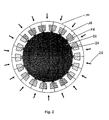
- the motor 1 shown in FIG. 1 is designed as a basic shaft machine and comprises a rotor 10 with permanent magnets 12 and a stator 14.
- the stator 14 has stator segments 16 of laminated iron parts with windings 18, which are arranged on a desired division providing insulating bodies 20. To build the stator 14, the stator segments 16 are connected together. The process for arranging windings on the stator 14 is thus reduced to individual operations for arranging the windings 18 on the stator segments 16.
- the windings 18 can be produced in a simple manner and inexpensively by automatic winding machines.
- stator 14 To build up the stator 14, the wound stator segments 16 are pressed onto an internal mandrel (not shown) which defines the air gap side stator diameter. The stator segments 16 are then connected to each other by casting or gluing or secured by a bandage.
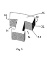
- an internal mandrel 22 shown in FIG. 2 can also be used, which has the projections 24 that ensure the division.
- the wound stator segments 16 are pressed onto the inner mandrel 40 in the direction of the arrows 26 in order to build up the stator 14.
- stator segments 16 of the basic-shaft machine 1 are constructed from individual sheets 28 which are insulated from one another electrically.
- the surfaces 30 of the stator segments 16 which come into contact with the structure of the stator 14 are insulated by an electrically nonconductive layer 32 prior to assembly.
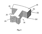
- FIG. 4 shows a possible form of a recess 34 for a stator pole segment 16.
- the recesses 34 extend parallel to the axis of rotation (not designated) of the stator 14 and have, for example, the shape of a circular section for a cross section perpendicular to the axis of rotation of the stator 14.
- the loss of effective pole area through the recess can be compensated by reducing the air gap, so that the maximum flux through the stator pole is not changed.
- additional cooling is made possible.
- the windings 18 are arranged in grooves 36 of the stator segments 16.
- the winding conductors 38 of the windings 18 are made by means of an orthocyclic winding process, with the winding conductors 30 crossing on one or both end sides of the stator 14 and running parallel between the poles in the densest packing.
- a schematic cross-sectional view through one of the stator segments 16 with a winding 18 arranged thereon is shown in FIG. 5.
- the winding conductors 38 can be crimped after winding individual layers or after winding a stator segment.
- additional windings may be arranged in the slots 36.
- the number of windings and the type of winding arrangement depend on the conductor cross-section of the windings, the shape of the slots, the dimensions of the stator, the desired electrical characteristics of a motor having the stator 14, and so forth.
- the stator 14 is made substantially in one piece, i. not the stator segments 16 described above are used.
- orthocyclic windings are used with closest packing of the winding conductors 38 in the grooves 36 between the poles.
- projections 42 are formed on the stator back, which are supported on installation on inner surfaces of a housing. The number of projections 42 may differ from the illustrated number.
- the windings 18 of the stator 14, which are designed as single-pole windings, can be operated individually or in groups or in blocks.
- the windings 18 are connected individually or in groups or in blocks to a control / power device (not shown).
- the windings 18 are controlled or operated under current control, whereby an optimal commutation of the stator 14 is achieved.
- stator 14 it is possible to change the number of the activated windings 18 by the control method without constructively modifying the stator 12. This can be done by interconnecting the individual coils in star or ring configuration or by any other blockwise summary.
- stator 14 can simple manner to different operating conditions and types as well as to different applications, for example, for use with different types of robot joints adapted.
- the windings 18 are combined in phases into phases, which are indicated in FIGS. 1, 2 and 6 by the same hatching. Adjacent windings 18 have an opposite sense of winding.
- a further optimization of the stator 14 for operation in the block clock is achieved when in the powered, switched-on windings 18 by the time-varying exciter field, a voltage is induced, which is constant during the switching phases.
- a voltage is induced, which is constant during the switching phases.
- a motor with low currentless reluctance torques is achieved when pole pair numbers of the rotor 10 and the stator 14 differ.
- the stator 14 has eighteen poles, while the rotor 10th twenty permanent magnets 12 has.
- the permanent magnets 12 are arranged with alternating polarity and may be composed of smaller, individual magnets.
- the interconnection of the windings 18 to groups of three poles and two groups per phase ensures good harmonic suppression with a simultaneously high winding factor of 0.9598 in operation as a three-phase fundamental wave machine. Due to the ten pole pairs of the motor 1, the rotating electrical field rotates at ten times the frequency of the rotor 10.
- At least one pair of windings 18 forming one pole of the stator 14 may be switched off, since the stator 14 is one pole pair less than the rotor 10 having. That is, no energy is supplied to these windings 18.
- the windings 18 are operated block-clocked.
- pole pairs of the stator 14 forming windings 18 are each controlled separately, wherein in the direction of rotation of the rotor 10 at least one Polcru vome is switched on, while in the direction of rotation of the rotor 10 at least one pole pair is turned off at the end.
- the block timing allows for pole pair windings 18 three different switching states.
- the windings 18, which are to generate a magnetic field, current is supplied with a negative or positive sign. Pairs of windings 18 which are not intended to generate a magnetic field are switched off. In this way you get blocks of on and off windings.
- the circuit diagram of the windings 18 shifts with respect to the stator 14 in the direction of rotation of the rotor 10, wherein the "electrical rotation speed" of the circuit diagram over the mechanical rotational speed of the rotor 10 is multiplied by the number of pole pairs.
- the areas of the stator 14 opposite the permanent magnets 12 can be made wider than would be necessary for an overlap with the permanent magnets 12 of the rotor 10.
- the pole forks formed in this way have such a large distance from one another that during rotations of the rotor 10 from positions in which maximum magnetic fluxes are generated by corresponding windings 18, partial fluxes of adjacent permanent magnets 12 are already recorded at angles than in a conventional stator the case would be.
- the rotor 10 is directly connected to a harmonic drive shown in Fig. 7.
- a wave generator 44 of the harmonic drive transmission on an outer peripheral surface (not designated) of the rotor 10 is arranged.
- the wave generator 70 can be connected to the rotor 10 directly, ie without the use of additional mechanical connection means (eg shafts, couplings and the like). This reduces the required installation space and the weight for the motor gear unit.
- a harmonic drive transmission ( Figure 7) consists of the wave generator 44, an elliptical steel disc with a center hub and a special elliptically deformable ball bearing mounted on it, a flex spline 46, a cylindrically deformable steel outer spline, and a circular spline 48 cylindrical ring with internal toothing.
- the elliptical wave generator 44 is driven by the rotor 10 and deforms via its ball bearing the flexspline 46 which is in the opposite areas of the large ellipse axis of the wave generator 44 with the internal splined circular spline 48 is engaged.
- Harmonic Drive gearboxes are particularly suitable for use with robots, as they enable backlash-free, high one-step reduction ratios. This is particularly important in robots that are used for high-precision positioning tasks.
- Special requirements for articulated drives for lightweight robots are set to the required (electrical) power for moments to be delivered and in particular the standstill torque.
- the required power depends, among other things, on the geometrical dimensions of the stator and rotor, the available space for the arrangement of and, in the case of a permanent-magnet-excited DC motor, the permanent magnets.
Claims (17)
- Moteur électrique (1), comprenant :- un rotor (10) et- un stator (14) à enroulements (18), lesquels sont réalisés en tant que bobinages d'excitation individuels et sont groupés individuellement ou en blocs pour une alimentation en énergie,- le stator (14) comprenant des segments statoriques (16), lesquels présentent des surfaces de connexion (30) qui sont pour l'essentiel planes dans la direction radiale pour la connexion entre les segments statoriques (16) et qui présentent une couche (32) électriquement non conductrice pour l'isolation des segments statoriques (16).
- Moteur électrique (1) selon la revendication 1,
caractérisé en ce que les bobinages (18) sont agencés sur le stator (14) au niveau de plans tangents. - Moteur électrique (1) selon la revendication 1,
caractérisé en ce que les bobinages (18) sont agencés sur le stator (14) au niveau de plans radiaux. - Moteur électrique (1) selon l'une des revendications 1 à 3,
caractérisé en ce qu'un premier nombre prédéterminé de pôles du stator (14) est respectivement connecté en série en tant que groupe, et un second nombre prédéterminé de groupes, décalés de 360° divisé par le produit du second nombre prédéterminé et du nombre de phases du moteur électrique (1), est connecté en parallèle ou en série. - Moteur électrique (1) selon l'une des revendications 1 à 4,
caractérisé en ce que les bobinages (18) sont conçus pour être, groupés individuellement ou en blocs, reliés de manière contrôlée à une alimentation en énergie. - Moteur électrique (1) selon l'une des revendications 1 à 5,
caractérisé en ce que le nombre de paires de pôles du rotor (10) diffère d'au moins un pôle du nombre de paires de pôles du stator (14). - Moteur électrique (1) selon l'une des revendications 1 à 6,
caractérisé en ce que les pôles du stator (14) présentent chacun au moins un évidement (34). - Moteur électrique (1) selon l'une des revendications 1 à 7,
caractérisé en ce que le rotor (10) présente des aimants permanents (12) et les surfaces des pôles du stator (14) opposées aux aimants permanents (12) sont supérieures aux surfaces correspondantes de chaque aimant permanent (12). - Moteur électrique (1) selon l'une des revendications 1 à 8,
caractérisé en ce que les segments statoriques (16) sont scellés au stator (14) ou fixés par le biais d'un bandage ou dans un logement pour former le stator (14). - Moteur électrique (1) selon l'une des revendications 1 à 9,
caractérisé en ce que les bobinages d'excitation individuels sont respectivement agencés au niveau de plans tangents sur l'un des segments statoriques (16). - Moteur électrique (1) selon l'une des revendications 1 à 9,
caractérisé en ce que les bobinages d'excitation individuels sont respectivement agencés au niveau de plans radiaux sur l'un ou sur deux des segments statoriques (16). - Moteur électrique (1 ) selon l'une des revendications 1 à 11,
caractérisé en ce que les bobinages (18) présentent des conducteurs (38) qui sont agencés selon la méthode de bobinage orthocyclique et qui courent parallèlement entre les pôles du stator (14). - Moteur électrique (1) selon l'une des revendications 1 à 12,
caractérisé en ce que les bobinages (18) présentent des conducteurs (38) qui sont disposés selon la méthode de bobinage orthocyclique et qui se croisent sur une face ou sur les deux faces du pôle correspondant. - Bloc moteur, comprenant- un moteur électrique (1) selon l'une des revendications 1 à 13, et- un Wave Generator (44) pour réducteur Harmonic Drive,- le rotor (10) étant directement relié au Wave Generator (44).
- Bloc moteur selon la revendication 14,
caractérisé en ce que le rotor (10) est un inducteur extérieur et le Wave Generator (44) est disposé sur une surface circonférentielle extérieure du rotor (10), le diamètre extérieur de la surface circonférentielle extérieure du rotor (10) correspondant pour l'essentiel au diamètre intérieur du Wave Generator (44). - Bloc moteur selon la revendication 14,
caractérisé en ce que le rotor (10) est un inducteur intérieur présentant une zone qui fait saillie du stator (14) et sur laquelle est agencé le Wave Generator (44). - Moteur électrique (1), comprenant un rotor (10), et un stator (14)
caractérisé en ce que- le nombre de paires de pôles du rotor (10) diffère d'au moins un pôle du nombre de paires de pôles du stator (14),- un premier nombre prédéterminé de pôles du stator (14) est respectivement connecté en série en tant que groupe, et un second nombre prédéterminé de groupes, décalés de 360° divisé par le produit du second nombre prédéterminé et du nombre de phases du moteur électrique (1), est connecté en parallèle ou en série,- le stator (14) comprenant des bobinages (18) réalisés en tant que bobinages d'excitation individuels, ces derniers étant groupés individuellement ou en blocs pour une alimentation en énergie,- les bobinages (18) étant agencés pour être, groupés individuellement ou en blocs, reliés de manière contrôlée à une alimentation en énergie,- les pôles du stator (14) présentant chacun au moins un évidement (34),- le rotor (10) présentant des aimants permanents (12) et les surfaces des pôles du stator (14) opposées aux aimants permanents (12) étant supérieures aux surfaces correspondantes de chaque aimant permanent (12),- le stator (14) comprenant des segments statoriques (16), lesquels présentent des surfaces de connexion (30) qui sont pour l'essentiel planes dans la direction radiale pour la connexion entre les segments statoriques (16) et qui présentent une couche (32) électriquement non conductrice pour l'isolation des segments statoriques (16),- les segments statoriques (16) étant scellés au stator (14) ou fixés par le biais d'un bandage ou dans un logement pour former le stator (14),- les enroulements d'excitation individuels étant respectivement agencés sur les segments statoriques (16), et- les enroulements (18) étant agencés au niveau de plans radiaux ou de plans tangents.
Applications Claiming Priority (3)
| Application Number | Priority Date | Filing Date | Title |
|---|---|---|---|
| DE10030129 | 2000-06-20 | ||
| DE2000130129 DE10030129A1 (de) | 2000-06-20 | 2000-06-20 | Vorrichtungen für Antriebseinheiten von Leichtbaurobotern |
| PCT/EP2001/006786 WO2001099254A1 (fr) | 2000-06-20 | 2001-06-15 | Dispositifs pour unites d'entrainement de robots |
Publications (2)
| Publication Number | Publication Date |
|---|---|
| EP1293024A1 EP1293024A1 (fr) | 2003-03-19 |
| EP1293024B1 true EP1293024B1 (fr) | 2006-07-05 |
Family
ID=7646239
Family Applications (1)
| Application Number | Title | Priority Date | Filing Date |
|---|---|---|---|
| EP01964988A Expired - Lifetime EP1293024B1 (fr) | 2000-06-20 | 2001-06-15 | Dispositifs pour unites d'entrainement de robots |
Country Status (3)
| Country | Link |
|---|---|
| EP (1) | EP1293024B1 (fr) |
| DE (2) | DE10030129A1 (fr) |
| WO (1) | WO2001099254A1 (fr) |
Cited By (2)
| Publication number | Priority date | Publication date | Assignee | Title |
|---|---|---|---|---|
| DE102014000690A1 (de) * | 2014-01-17 | 2015-07-23 | Kienle + Spiess Gmbh | Ringförmiges Lamellenpaket aus Einzelzahnpaketen sowie Verfahren zur Herstellung eines Lamellenpaketes |
| DE102014002627A1 (de) * | 2014-02-27 | 2015-08-27 | Sew-Eurodrive Gmbh & Co Kg | Elektromaschine |
Families Citing this family (5)
| Publication number | Priority date | Publication date | Assignee | Title |
|---|---|---|---|---|
| DE102009005496A1 (de) | 2009-01-21 | 2010-07-22 | Kuka Roboter Gmbh | Manipulator mit einem Außenläufermotor |
| DE102009060838A1 (de) * | 2009-12-29 | 2011-07-14 | Robert Bosch GmbH, 70469 | Stator einer elektrischen Maschine sowie Verfahren zum Herstellen eines solchen |
| DE102011118548B4 (de) | 2011-11-16 | 2019-07-04 | Diehl Aviation Laupheim Gmbh | Gepäckbehälter für ein Flugzeug und Flugzeug mit dem Gepäckbehälter |
| DE102011118550B4 (de) * | 2011-11-16 | 2019-07-04 | Diehl Aviation Laupheim Gmbh | Gepäckablagefach für ein Flugzeug und Flugzeug mit dem Gepäckablagefach |
| DE102014213595A1 (de) * | 2014-07-14 | 2016-01-14 | Schaeffler Technologies AG & Co. KG | Vorrichtung und Verfahren zur Herstellung eines Stators einer elektrischen Maschine |
Family Cites Families (20)
| Publication number | Priority date | Publication date | Assignee | Title |
|---|---|---|---|---|
| DE222404C (fr) * | ||||
| US1756672A (en) * | 1922-10-12 | 1930-04-29 | Allis Louis Co | Dynamo-electric machine |
| NL6702187A (fr) * | 1967-02-14 | 1968-08-15 | ||
| CH523618A (de) * | 1970-05-01 | 1972-05-31 | Rotel Ag | Verfahren zum Anbringen eines Stator- oder Rotoreisenkernes auf Wickelspulen eines Stators oder Rotors und Eisenkern zur Durchführung des Verfahrens |
| JPS57131088A (en) * | 1980-08-11 | 1982-08-13 | Matsushita Electric Works Ltd | Watch |
| US4375602A (en) * | 1980-09-08 | 1983-03-01 | Usm Corporation | One lobed motor |
| DE3231553A1 (de) * | 1982-08-25 | 1984-03-01 | Liebherr-Aero-Technik Gmbh, 8998 Lindenberg | Elektromechanischer stellantrieb |
| US4550267A (en) * | 1983-02-18 | 1985-10-29 | Sundstrand Corporation | Redundant multiple channel electric motors and generators |
| DE3317509A1 (de) * | 1983-05-13 | 1984-11-15 | Teldix Gmbh, 6900 Heidelberg | Stellantrieb fuer eine an einem satelliten angeordnete nachfuehrbare antenne, sonnenkollektor o.ae. |
| DE3578281D1 (de) * | 1984-07-11 | 1990-07-19 | Matsushita Electric Ind Co Ltd | Elektrischer drehmotor. |
| DE3723768A1 (de) * | 1987-07-17 | 1989-01-26 | Freund H Mora Messgeraete | Am ende eines querarms eines mess- oder anreissgeraetes befestigbarer aufnahmekopf |
| DE4012806C2 (de) * | 1990-04-21 | 1998-11-26 | Alcatel Kabel Ag | Mit einem isolierten Leiter hergestellter Wickel |
| DE4036370A1 (de) * | 1990-11-15 | 1992-05-21 | Rheinmetall Gmbh | Verfahren und vorrichtung zur kontrolle des wicklungsverlaufes orthozyklisch gewickelter spulen |
| US5252870A (en) * | 1991-03-01 | 1993-10-12 | Jacobsen Stephen C | Magnetic eccentric motion motor |
| JPH04365503A (ja) * | 1991-06-13 | 1992-12-17 | Sumitomo Electric Ind Ltd | U軸ボーリングヘッド |
| JP3355700B2 (ja) * | 1993-06-14 | 2002-12-09 | 松下電器産業株式会社 | 回転電機の固定子 |
| GB2310545B (en) * | 1996-02-22 | 2000-04-19 | Honda Motor Co Ltd | Stator core and method and apparatus for assembling same |
| US5912522A (en) * | 1996-08-22 | 1999-06-15 | Rivera; Nicholas N. | Permanent magnet direct current (PMDC) machine with integral reconfigurable winding control |
| JP3568364B2 (ja) * | 1996-09-30 | 2004-09-22 | 松下電器産業株式会社 | 回転電機のコア |
| JPH1132457A (ja) * | 1997-07-10 | 1999-02-02 | Toyota Motor Corp | 回転電機のステータ |
-
2000
- 2000-06-20 DE DE2000130129 patent/DE10030129A1/de not_active Withdrawn
-
2001
- 2001-06-15 DE DE50110404T patent/DE50110404D1/de not_active Expired - Lifetime
- 2001-06-15 EP EP01964988A patent/EP1293024B1/fr not_active Expired - Lifetime
- 2001-06-15 WO PCT/EP2001/006786 patent/WO2001099254A1/fr active IP Right Grant
Cited By (2)
| Publication number | Priority date | Publication date | Assignee | Title |
|---|---|---|---|---|
| DE102014000690A1 (de) * | 2014-01-17 | 2015-07-23 | Kienle + Spiess Gmbh | Ringförmiges Lamellenpaket aus Einzelzahnpaketen sowie Verfahren zur Herstellung eines Lamellenpaketes |
| DE102014002627A1 (de) * | 2014-02-27 | 2015-08-27 | Sew-Eurodrive Gmbh & Co Kg | Elektromaschine |
Also Published As
| Publication number | Publication date |
|---|---|
| WO2001099254A1 (fr) | 2001-12-27 |
| DE50110404D1 (de) | 2006-08-17 |
| DE10030129A1 (de) | 2002-01-17 |
| EP1293024A1 (fr) | 2003-03-19 |
Similar Documents
| Publication | Publication Date | Title |
|---|---|---|
| DE69827299T2 (de) | Elektrischer motor oder generator | |
| DE60315044T2 (de) | Wellgetriebemotor | |
| DE60219096T2 (de) | Transportsystem und dynamoelektrische Maschine | |
| EP1997214B1 (fr) | Machine électrique notamment générateur | |
| EP1685642B1 (fr) | Transmission magnetodynamique a reglage continu | |
| EP1797630B1 (fr) | Moteur d'entrainement direct synchrone multipole, lineaire ou rotatif | |
| EP1314236B1 (fr) | Machine electrique pour frequences de demagnetisation elevees | |
| EP3479462B1 (fr) | Système de machine électrique | |
| DE69814356T2 (de) | Bürstenloser permanenterregter Elektromotor | |
| EP2891235B1 (fr) | Convertisseur électromécanique | |
| EP3736943A1 (fr) | Machine à flux transversal rotative à phases multiples | |
| DE3927454C2 (fr) | ||
| EP1293024B1 (fr) | Dispositifs pour unites d'entrainement de robots | |
| EP1428306A1 (fr) | Moteur electrique a commutation electronique a bobines paralleles a l'axe | |
| DE102009004474B4 (de) | Transversalflussmaschine mit scheibenförmigen Rotoren | |
| DE60125194T2 (de) | Wanderfeld Synchronmotor | |
| DE19704769C2 (de) | Mehrsträngige Synchronmaschine mit Permanentmagneten und Spulenmodulen | |
| DE112014002642T5 (de) | Bürstenloser Motor des Innenläufertyps | |
| DE102018104418A1 (de) | Elektromagnetisch betätigter Aktor für elektrische Maschine und elektrische Maschine mit elektromagnetisch betätigtem Aktor | |
| DE10110719C2 (de) | Transversalflußmaschine mit mehreren einsträngigen Erregerteilen | |
| EP1130739A2 (fr) | Stator pour une machine électrique | |
| WO2014071960A1 (fr) | Moteur électrique présentant une inductance améliorée, et procédé d'enroulement et de connexion de bobines | |
| DE2105737C3 (de) | Mehrphasiger elektrischer Schrittmotor | |
| AT522827B1 (de) | Verkoppeltes Maschinensystem | |
| DE202008016680U1 (de) | Rotativer Motor |
Legal Events
| Date | Code | Title | Description |
|---|---|---|---|
| PUAI | Public reference made under article 153(3) epc to a published international application that has entered the european phase |
Free format text: ORIGINAL CODE: 0009012 |
|
| 17P | Request for examination filed |
Effective date: 20021111 |
|
| AK | Designated contracting states |
Kind code of ref document: A1 Designated state(s): AT BE CH CY DE DK ES FI FR GB GR IE IT LI LU MC NL PT SE TR |
|
| RBV | Designated contracting states (corrected) |
Designated state(s): DE FR GB SE |
|
| GRAP | Despatch of communication of intention to grant a patent |
Free format text: ORIGINAL CODE: EPIDOSNIGR1 |
|
| GRAS | Grant fee paid |
Free format text: ORIGINAL CODE: EPIDOSNIGR3 |
|
| GRAA | (expected) grant |
Free format text: ORIGINAL CODE: 0009210 |
|
| RAP1 | Party data changed (applicant data changed or rights of an application transferred) |
Owner name: DEUTSCHES ZENTRUM FUER LUFT- UND RAUMFAHRT E.V. |
|
| AK | Designated contracting states |
Kind code of ref document: B1 Designated state(s): DE FR GB SE |
|
| REG | Reference to a national code |
Ref country code: GB Ref legal event code: FG4D Free format text: NOT ENGLISH |
|
| GBT | Gb: translation of ep patent filed (gb section 77(6)(a)/1977) |
Effective date: 20060706 |
|
| REF | Corresponds to: |
Ref document number: 50110404 Country of ref document: DE Date of ref document: 20060817 Kind code of ref document: P |
|
| REG | Reference to a national code |
Ref country code: SE Ref legal event code: TRGR |
|
| ET | Fr: translation filed | ||
| PLBE | No opposition filed within time limit |
Free format text: ORIGINAL CODE: 0009261 |
|
| STAA | Information on the status of an ep patent application or granted ep patent |
Free format text: STATUS: NO OPPOSITION FILED WITHIN TIME LIMIT |
|
| 26N | No opposition filed |
Effective date: 20070410 |
|
| REG | Reference to a national code |
Ref country code: FR Ref legal event code: PLFP Year of fee payment: 16 |
|
| REG | Reference to a national code |
Ref country code: FR Ref legal event code: PLFP Year of fee payment: 17 |
|
| REG | Reference to a national code |
Ref country code: FR Ref legal event code: PLFP Year of fee payment: 18 |
|
| PGFP | Annual fee paid to national office [announced via postgrant information from national office to epo] |
Ref country code: FR Payment date: 20200520 Year of fee payment: 20 Ref country code: DE Payment date: 20200518 Year of fee payment: 20 |
|
| PGFP | Annual fee paid to national office [announced via postgrant information from national office to epo] |
Ref country code: GB Payment date: 20200529 Year of fee payment: 20 Ref country code: SE Payment date: 20200609 Year of fee payment: 20 |
|
| REG | Reference to a national code |
Ref country code: DE Ref legal event code: R071 Ref document number: 50110404 Country of ref document: DE |
|
| REG | Reference to a national code |
Ref country code: GB Ref legal event code: PE20 Expiry date: 20210614 |
|
| REG | Reference to a national code |
Ref country code: SE Ref legal event code: EUG |
|
| PG25 | Lapsed in a contracting state [announced via postgrant information from national office to epo] |
Ref country code: GB Free format text: LAPSE BECAUSE OF EXPIRATION OF PROTECTION Effective date: 20210614 |