EP1292404B1 - Coolant delivery device - Google Patents
Coolant delivery device Download PDFInfo
- Publication number
- EP1292404B1 EP1292404B1 EP01930690A EP01930690A EP1292404B1 EP 1292404 B1 EP1292404 B1 EP 1292404B1 EP 01930690 A EP01930690 A EP 01930690A EP 01930690 A EP01930690 A EP 01930690A EP 1292404 B1 EP1292404 B1 EP 1292404B1
- Authority
- EP
- European Patent Office
- Prior art keywords
- housing
- inner edge
- concave inner
- work roll
- interior surfaces
- Prior art date
- Legal status (The legal status is an assumption and is not a legal conclusion. Google has not performed a legal analysis and makes no representation as to the accuracy of the status listed.)
- Expired - Lifetime
Links
Images


Classifications
-
- B—PERFORMING OPERATIONS; TRANSPORTING
- B21—MECHANICAL METAL-WORKING WITHOUT ESSENTIALLY REMOVING MATERIAL; PUNCHING METAL
- B21B—ROLLING OF METAL
- B21B27/00—Rolls, roll alloys or roll fabrication; Lubricating, cooling or heating rolls while in use
- B21B27/06—Lubricating, cooling or heating rolls
- B21B27/10—Lubricating, cooling or heating rolls externally
Definitions
- This invention relates generally to coolant delivery devices, and is concerned in particular with coolant delivery devices of the type employed to cool work rolls in a rolling mill. (see for example GB-A-1281 404).
- rolling mill coolant delivery devices are fabricated from pipes which are bent into the desired configuration and then drilled at various angles to accommodate smaller tubes defining delivery nozzles.
- Such bending and drilling procedures make it difficult to achieve accuracy and repeatability, thus compromising cooling efficiency while contributing disadvantageously to high production costs.
- the present invention addresses these problems by providing an improved coolant delivery apparatus according to claim 1.
- Each half section is accurately machined with manifold and branch delivery grooves which coact when the half sections are assembled to provide an efficient coolant delivery system.
- a coolant delivery device in accordance with the present invention is generally depicted at 10 at a location adjacent to a work roll 12. As the work roll undergoes normal wear, it will be progressively ground down to a reduced diameter indicated at 12', at which time it will be discarded.
- the cooling device comprises a housing having a generally concave scalloped inner edge 13 configured and dimensioned to partially surround the surface of work roll 12.
- the housing is subdivided into two mating half sections 14a, 14b held together by any convenient means such as for example the screws 16 shown in the drawings.
- the abutting interior surfaces of the half sections 14a, 14b each have a manifold groove 18 with branch grooves 20 leading the a scalloped inner edge 13.
- manifold grooves 18 coact in a confronting relationship to define a manifold conduit 24, and the branch grooves 20 coact in a confronting relationship to define delivery nozzles 26 arranged at appropriate angles selected to achieve optimum cooling of the roll 12.
- a fluid coolant which can be a liquid and/or a gas, is fed to the manifold conduit 24 via an inlet port 28 in half section 14a, and is then delivered to the roll surface via nozzles 26.
- the concave inner edge 13 is formed on a generally arcuate first position "A" of the housing, and a generally arcuate oppositely curved portion "B" of the housing has a convex inner edge 25 providing a continuation of the edge 13.
- the housing portions A, B are provided, respectively, with generally hook-shaped ends defining notches 30a, 30b.
- Bolts 32a, 32b extend through the notches 30a, 30b and serve to secure the coolant delivery device to the roll stand structures 34.
- Notch 30a is somewhat deeper than notch 30b.
- the device can be pivotally adjusted about the axis of bolt 32b to accommodate the different roll diameters resulting from progressive roll grinding. Loosening of the bolts 32a, 32b also allows the device to be easily and quickly removed for replacement by another new or refurbished unit.
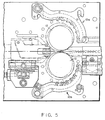
- Figure 5 depicts an installation of two coolant devices 10a, 10b, one being a mirror image of the other, and each being positioned adjacent to one of a pair of work rolls 12.
- the delivery device By dividing the delivery device into two mating half sections, it can be produced easily on common machinery with readily available tools, e.g., basic modern three axis milling machines. Much more freedom can be enjoyed in choosing the number of delivery nozzles, as well as their location, and angular disposition, without unnecessarily increasing the cost of the device.
- the cross sectional configuration of the delivery nozzles can be varied with considerable freedom, including for example cross, oval, T-shape, or diamond cross sections.
- the delivery nozzles can also be located above, at or below, the centerline of the manifold conduit to achieve a wide pattern of coolant delivery. Replaceable inserts for the nozzles and/or a liner for the manifold conduit is also a design option.
- Choice of materials is greatly expanded in comparison to conventional pipe-like devices. Material selection need not be limited to that which can withstand bending, machining and welding.
- the device of the present invention can readily be made from many different materials including metal plate, cast metal, plastic, ceramic, or composite materials. Thus, in a rolling mill environment where cooling water can often have entrained abrasive particles, an abrasion resistant material can be used. If the cooling water contains minerals that can adhere to passage walls, a non-stick lining or coating can be applied to interior surfaces. Corrosion-resistant coating may also be employed where appropriate.
- the geometry of the manifold conduit can also be varied to provide each delivery nozzle with near equal pressure, thereby further optimizing coolant delivery.
- the device can easily be disassembled for cleaning and replacement of internal liner components where utilized.
Landscapes
- Engineering & Computer Science (AREA)
- Mechanical Engineering (AREA)
- Nozzles (AREA)
- Spray Control Apparatus (AREA)
- Acyclic And Carbocyclic Compounds In Medicinal Compositions (AREA)
- Electron Sources, Ion Sources (AREA)
- Electrical Discharge Machining, Electrochemical Machining, And Combined Machining (AREA)
- Grinding Of Cylindrical And Plane Surfaces (AREA)
- Rolls And Other Rotary Bodies (AREA)
Abstract
Description
Claims (6)
- Apparatus for applying a fluid coolant to the surface of rotating work roll in a rolling mill, said apparatus comprising:a housing having a generally concave inner edge configured and dimensioned to partially surround the surface of the work roll, characterised in that said housing being subdivided into mating half sections having abutting interior surfaces;first grooves in said interior surfaces arranged in a confronting relationship to define a manifold conduit;second grooves in said interior surfaces arranged in a confronting relationship to define nozzle conduits leading from said manifold conduit to said concave inner edge; andan inlet in said housing through which a fluid coolant may be fed to said manifold conduit for application via said nozzle conduits to the surface of the work roll.
- The apparatus of claim 1 wherein said concave inner edge has a scalloped configuration.
- The apparatus as claimed in claim 1 wherein said concave inner edge is formed on a generally arcuate first portion of said housing.
- The apparatus as claimed in claim 3 wherein said housing has a generally arcuate oppositely curved second portion with a convex inner edge providing a continuation of said concave inner edge.
- The apparatus as claimed in claim 4 wherein said first and second housing portions are provided, respectively, with first and second notches configured and dimensioned to receive and coact in mechanical interengagement with fasteners serving to secure said housing to a support structure.
- The apparatus as claimed in claim 5 wherein the depth of said first notch is greater than the depth of said second notch to thereby accommodate pivotal adjustment of said housing about the fastener received in said first notch.
Applications Claiming Priority (5)
| Application Number | Priority Date | Filing Date | Title |
|---|---|---|---|
| US21167900P | 2000-06-15 | 2000-06-15 | |
| US211679P | 2000-06-15 | ||
| US09/818,164 US6385989B1 (en) | 2000-06-15 | 2001-03-27 | Coolant delivery device |
| US818164 | 2001-03-27 | ||
| PCT/US2001/013153 WO2001096037A1 (en) | 2000-06-15 | 2001-04-24 | Coolant delivery device |
Publications (2)
| Publication Number | Publication Date |
|---|---|
| EP1292404A1 EP1292404A1 (en) | 2003-03-19 |
| EP1292404B1 true EP1292404B1 (en) | 2004-11-17 |
Family
ID=26906357
Family Applications (1)
| Application Number | Title | Priority Date | Filing Date |
|---|---|---|---|
| EP01930690A Expired - Lifetime EP1292404B1 (en) | 2000-06-15 | 2001-04-24 | Coolant delivery device |
Country Status (13)
| Country | Link |
|---|---|
| US (1) | US6385989B1 (en) |
| EP (1) | EP1292404B1 (en) |
| JP (1) | JP3776885B2 (en) |
| KR (1) | KR100757553B1 (en) |
| CN (1) | CN1144631C (en) |
| AT (1) | ATE282486T1 (en) |
| AU (1) | AU2001257198A1 (en) |
| BR (1) | BR0111696B1 (en) |
| CA (1) | CA2411280C (en) |
| DE (1) | DE60107242T2 (en) |
| ES (1) | ES2227183T3 (en) |
| MX (1) | MXPA02012418A (en) |
| WO (1) | WO2001096037A1 (en) |
Families Citing this family (10)
| Publication number | Priority date | Publication date | Assignee | Title |
|---|---|---|---|---|
| IT1315084B1 (en) * | 2000-04-20 | 2003-02-03 | Danieli Off Mecc | COOLING DEVICE FOR ROLLING RINGS AND RELATED PROCEDURE. |
| EP2014379A1 (en) * | 2007-06-04 | 2009-01-14 | ArcelorMittal France | Rolling mill with cooling device and rolling process |
| CN101722191B (en) * | 2009-11-27 | 2012-09-26 | 中色科技股份有限公司 | Rolling mill roll cooling device |
| CN102049417B (en) * | 2010-11-04 | 2012-11-14 | 山东钢铁股份有限公司 | Combined adjustable type rolling machine roll collar cooling device |
| EP2489446A1 (en) * | 2011-02-17 | 2012-08-22 | Linde Aktiengesellschaft | Nozzle header |
| US9427788B2 (en) | 2013-11-13 | 2016-08-30 | Primetals Technologies USA LLC | Cooling device for a rolling mill work roll |
| DE102014224318A1 (en) * | 2014-11-27 | 2016-06-02 | Sms Group Gmbh | Apparatus and method for cooling a roll |
| GB2537162B (en) * | 2015-04-10 | 2017-04-19 | Primetals Technologies Austria GmbH | Work roll cooling apparatus and method |
| CN104942009B (en) * | 2015-06-25 | 2017-08-25 | 江苏永钢集团有限公司 | The special cooling device of rolling on edge groove |
| DE102016223131A1 (en) * | 2016-09-06 | 2018-03-08 | Sms Group Gmbh | Apparatus and method for applying a liquid medium to a roll and / or to a rolling stock and / or for removing the liquid medium |
Family Cites Families (15)
| Publication number | Priority date | Publication date | Assignee | Title |
|---|---|---|---|---|
| US1278617A (en) | 1915-08-02 | 1918-09-10 | Morgan Construction Co | Rolling-mill. |
| US3372916A (en) * | 1965-09-21 | 1968-03-12 | Braun & Co C F | Apparatus for stress-relieving pipe welds |
| GB1281404A (en) | 1969-05-01 | 1972-07-12 | Ashlow Steel & Eng Co | Improvements in or relating to rolling mills |
| US3998084A (en) * | 1974-11-01 | 1976-12-21 | Marotta Scientific Controls, Inc. | Cooling spray system for rolling mill |
| KR880000759B1 (en) * | 1978-11-03 | 1988-05-06 | 제이. 알. 바췔러 | A cooling apparatus of steel strip |
| JPS5619911A (en) * | 1979-07-25 | 1981-02-25 | Sumitomo Metal Ind Ltd | Cooling method for rolling roll made of sintered hard alloy |
| US4418559A (en) * | 1981-12-08 | 1983-12-06 | Gulf & Western Manufacturing Co. | Roll coolant distribution header |
| US4439991A (en) * | 1982-06-11 | 1984-04-03 | Stelco Inc. | Method and apparatus for treating elongate materials |
| US4577482A (en) * | 1984-06-18 | 1986-03-25 | Wean United, Inc. | Method and apparatus for treating work rolls in a rolling mill |
| US4706485A (en) | 1986-12-15 | 1987-11-17 | Morgan Construction Company | Carrier module |
| US5046347A (en) * | 1989-10-10 | 1991-09-10 | Alcan International Limited | Coolant containment apparatus for rolling mills |
| US5212975A (en) * | 1991-05-13 | 1993-05-25 | International Rolling Mill Consultants, Inc. | Method and apparatus for cooling rolling mill rolls and flat rolled products |
| JP3238637B2 (en) * | 1996-11-12 | 2001-12-17 | 山陽特殊製鋼株式会社 | Detachable multi-row roll cooling water header for vertical rolling mill |
| DE59705540D1 (en) * | 1996-12-23 | 2002-01-10 | Sms Demag Ag | Wire rolling mill |
| DE19737735A1 (en) * | 1997-08-29 | 1999-03-04 | Schloemann Siemag Ag | Device and method for cooling the work rolls of a roll stand on the outlet side |
-
2001
- 2001-03-27 US US09/818,164 patent/US6385989B1/en not_active Expired - Lifetime
- 2001-04-24 EP EP01930690A patent/EP1292404B1/en not_active Expired - Lifetime
- 2001-04-24 AT AT01930690T patent/ATE282486T1/en active
- 2001-04-24 BR BRPI0111696-7A patent/BR0111696B1/en not_active IP Right Cessation
- 2001-04-24 DE DE60107242T patent/DE60107242T2/en not_active Expired - Lifetime
- 2001-04-24 JP JP2002510208A patent/JP3776885B2/en not_active Expired - Fee Related
- 2001-04-24 CA CA002411280A patent/CA2411280C/en not_active Expired - Lifetime
- 2001-04-24 AU AU2001257198A patent/AU2001257198A1/en not_active Abandoned
- 2001-04-24 CN CNB018111815A patent/CN1144631C/en not_active Expired - Fee Related
- 2001-04-24 ES ES01930690T patent/ES2227183T3/en not_active Expired - Lifetime
- 2001-04-24 MX MXPA02012418A patent/MXPA02012418A/en active IP Right Grant
- 2001-04-24 WO PCT/US2001/013153 patent/WO2001096037A1/en active IP Right Grant
- 2001-04-24 KR KR1020027017082A patent/KR100757553B1/en active IP Right Grant
Also Published As
| Publication number | Publication date |
|---|---|
| EP1292404A1 (en) | 2003-03-19 |
| CN1144631C (en) | 2004-04-07 |
| DE60107242T2 (en) | 2005-10-27 |
| CN1436106A (en) | 2003-08-13 |
| BR0111696B1 (en) | 2008-11-18 |
| KR100757553B1 (en) | 2007-09-10 |
| MXPA02012418A (en) | 2003-06-06 |
| WO2001096037A1 (en) | 2001-12-20 |
| BR0111696A (en) | 2003-07-01 |
| JP2004503383A (en) | 2004-02-05 |
| ATE282486T1 (en) | 2004-12-15 |
| US6385989B1 (en) | 2002-05-14 |
| JP3776885B2 (en) | 2006-05-17 |
| CA2411280A1 (en) | 2001-12-20 |
| CA2411280C (en) | 2007-09-25 |
| KR20030028759A (en) | 2003-04-10 |
| AU2001257198A1 (en) | 2001-12-24 |
| ES2227183T3 (en) | 2005-04-01 |
| DE60107242D1 (en) | 2004-12-23 |
Similar Documents
| Publication | Publication Date | Title |
|---|---|---|
| EP1292404B1 (en) | Coolant delivery device | |
| US9975186B2 (en) | Ejector drill system | |
| KR100663222B1 (en) | Throw-away cutting tool | |
| EP1759133B1 (en) | Cutting tools and roughened articles using surface roughening methods | |
| US6669118B2 (en) | Coherent jet nozzles for grinding applications | |
| US20050169718A1 (en) | Tool coolant application and direction assembly | |
| US10569347B2 (en) | Drilling system and methods for deep hole drilling | |
| JP4667387B2 (en) | Split grinding tool | |
| RU2237531C1 (en) | Apparatus for feeding cooling agent | |
| US6471573B1 (en) | Adapter for supplying lubricating fluid to a workpiece-engaging tool | |
| RU2307729C1 (en) | Grinding tool with vortex cooling | |
| GB2114030A (en) | Valve seat grinding device and tool for using the same | |
| US10967441B2 (en) | Drilling system and modular drilling head for deep hole drilling | |
| GB2152631A (en) | Assembled cylindrical roll tool with axially extending joint between parts | |
| CA1250454A (en) | Coolant supply shank for a rotating cutting tool | |
| CN220426941U (en) | Spiral end mill | |
| EP1222981B1 (en) | Engine cylinder block manufacture | |
| SU1652041A1 (en) | Device for reconditioning parts of types of center-crosses of universal joints | |
| Woon et al. | Deep hole gun drilling of nickel-based superalloys | |
| JP2002224733A (en) | Manufacturing apparatus for inner grooved metal tube |
Legal Events
| Date | Code | Title | Description |
|---|---|---|---|
| PUAI | Public reference made under article 153(3) epc to a published international application that has entered the european phase |
Free format text: ORIGINAL CODE: 0009012 |
|
| 17P | Request for examination filed |
Effective date: 20021211 |
|
| AK | Designated contracting states |
Kind code of ref document: A1 Designated state(s): AT BE CH CY DE DK ES FI FR GB GR IE IT LI LU MC NL PT SE TR Designated state(s): AT BE CH CY DE DK ES FI FR GB GR IE IT LI LU MC NL PT SE TR |
|
| AX | Request for extension of the european patent |
Extension state: AL LT LV MK RO SI |
|
| GRAP | Despatch of communication of intention to grant a patent |
Free format text: ORIGINAL CODE: EPIDOSNIGR1 |
|
| GRAS | Grant fee paid |
Free format text: ORIGINAL CODE: EPIDOSNIGR3 |
|
| GRAA | (expected) grant |
Free format text: ORIGINAL CODE: 0009210 |
|
| AK | Designated contracting states |
Kind code of ref document: B1 Designated state(s): AT BE CH CY DE DK ES FI FR GB GR IE IT LI LU MC NL PT SE TR |
|
| PG25 | Lapsed in a contracting state [announced via postgrant information from national office to epo] |
Ref country code: NL Free format text: LAPSE BECAUSE OF FAILURE TO SUBMIT A TRANSLATION OF THE DESCRIPTION OR TO PAY THE FEE WITHIN THE PRESCRIBED TIME-LIMIT Effective date: 20041117 Ref country code: LI Free format text: LAPSE BECAUSE OF FAILURE TO SUBMIT A TRANSLATION OF THE DESCRIPTION OR TO PAY THE FEE WITHIN THE PRESCRIBED TIME-LIMIT Effective date: 20041117 Ref country code: FI Free format text: LAPSE BECAUSE OF FAILURE TO SUBMIT A TRANSLATION OF THE DESCRIPTION OR TO PAY THE FEE WITHIN THE PRESCRIBED TIME-LIMIT Effective date: 20041117 Ref country code: TR Free format text: LAPSE BECAUSE OF FAILURE TO SUBMIT A TRANSLATION OF THE DESCRIPTION OR TO PAY THE FEE WITHIN THE PRESCRIBED TIME-LIMIT Effective date: 20041117 Ref country code: CH Free format text: LAPSE BECAUSE OF FAILURE TO SUBMIT A TRANSLATION OF THE DESCRIPTION OR TO PAY THE FEE WITHIN THE PRESCRIBED TIME-LIMIT Effective date: 20041117 Ref country code: BE Free format text: LAPSE BECAUSE OF FAILURE TO SUBMIT A TRANSLATION OF THE DESCRIPTION OR TO PAY THE FEE WITHIN THE PRESCRIBED TIME-LIMIT Effective date: 20041117 |
|
| REG | Reference to a national code |
Ref country code: GB Ref legal event code: FG4D |
|
| REG | Reference to a national code |
Ref country code: CH Ref legal event code: EP |
|
| REG | Reference to a national code |
Ref country code: IE Ref legal event code: FG4D |
|
| REF | Corresponds to: |
Ref document number: 60107242 Country of ref document: DE Date of ref document: 20041223 Kind code of ref document: P |
|
| PG25 | Lapsed in a contracting state [announced via postgrant information from national office to epo] |
Ref country code: GR Free format text: LAPSE BECAUSE OF FAILURE TO SUBMIT A TRANSLATION OF THE DESCRIPTION OR TO PAY THE FEE WITHIN THE PRESCRIBED TIME-LIMIT Effective date: 20050217 Ref country code: DK Free format text: LAPSE BECAUSE OF FAILURE TO SUBMIT A TRANSLATION OF THE DESCRIPTION OR TO PAY THE FEE WITHIN THE PRESCRIBED TIME-LIMIT Effective date: 20050217 |
|
| REG | Reference to a national code |
Ref country code: SE Ref legal event code: TRGR |
|
| REG | Reference to a national code |
Ref country code: ES Ref legal event code: FG2A Ref document number: 2227183 Country of ref document: ES Kind code of ref document: T3 |
|
| PG25 | Lapsed in a contracting state [announced via postgrant information from national office to epo] |
Ref country code: LU Free format text: LAPSE BECAUSE OF NON-PAYMENT OF DUE FEES Effective date: 20050424 Ref country code: CY Free format text: LAPSE BECAUSE OF FAILURE TO SUBMIT A TRANSLATION OF THE DESCRIPTION OR TO PAY THE FEE WITHIN THE PRESCRIBED TIME-LIMIT Effective date: 20050424 |
|
| PG25 | Lapsed in a contracting state [announced via postgrant information from national office to epo] |
Ref country code: IE Free format text: LAPSE BECAUSE OF NON-PAYMENT OF DUE FEES Effective date: 20050425 |
|
| PG25 | Lapsed in a contracting state [announced via postgrant information from national office to epo] |
Ref country code: MC Free format text: LAPSE BECAUSE OF NON-PAYMENT OF DUE FEES Effective date: 20050430 |
|
| NLV1 | Nl: lapsed or annulled due to failure to fulfill the requirements of art. 29p and 29m of the patents act | ||
| REG | Reference to a national code |
Ref country code: CH Ref legal event code: PL |
|
| PLBE | No opposition filed within time limit |
Free format text: ORIGINAL CODE: 0009261 |
|
| STAA | Information on the status of an ep patent application or granted ep patent |
Free format text: STATUS: NO OPPOSITION FILED WITHIN TIME LIMIT |
|
| 26N | No opposition filed |
Effective date: 20050818 |
|
| ET | Fr: translation filed | ||
| PG25 | Lapsed in a contracting state [announced via postgrant information from national office to epo] |
Ref country code: PT Free format text: LAPSE BECAUSE OF NON-PAYMENT OF DUE FEES Effective date: 20050417 |
|
| REG | Reference to a national code |
Ref country code: GB Ref legal event code: 732E Free format text: REGISTERED BETWEEN 20110310 AND 20110316 |
|
| REG | Reference to a national code |
Ref country code: DE Ref legal event code: R081 Ref document number: 60107242 Country of ref document: DE Owner name: SIEMENS INDUSTRY, INC. (N. D. GES. D. STAATES , US Free format text: FORMER OWNER: MORGAN CONSTRUCTION CO., WORCESTER, MASS., US Effective date: 20110209 Ref country code: DE Ref legal event code: R081 Ref document number: 60107242 Country of ref document: DE Owner name: PRIMETALS TECHNOLOGIES USA LLC, ALPHARETTA, US Free format text: FORMER OWNER: MORGAN CONSTRUCTION CO., WORCESTER, MASS., US Effective date: 20110209 |
|
| REG | Reference to a national code |
Ref country code: ES Ref legal event code: PC2A Owner name: SIEMENS INDUSTRY, INC. Effective date: 20110428 |
|
| REG | Reference to a national code |
Ref country code: FR Ref legal event code: TP |
|
| REG | Reference to a national code |
Ref country code: FR Ref legal event code: PLFP Year of fee payment: 16 |
|
| REG | Reference to a national code |
Ref country code: DE Ref legal event code: R082 Ref document number: 60107242 Country of ref document: DE Representative=s name: KINNSTAETTER, KLAUS, DIPL.-PHYS.UNIV., DE Ref country code: DE Ref legal event code: R081 Ref document number: 60107242 Country of ref document: DE Owner name: PRIMETALS TECHNOLOGIES USA LLC, ALPHARETTA, US Free format text: FORMER OWNER: SIEMENS INDUSTRY, INC. (N. D. GES. D. STAATES DELAWARE), BUFFALO GROVE, III., US |
|
| REG | Reference to a national code |
Ref country code: FR Ref legal event code: TP Owner name: PRIMETALS TECHNOLOGIES USA LLC, US Effective date: 20160928 |
|
| REG | Reference to a national code |
Ref country code: GB Ref legal event code: 732E Free format text: REGISTERED BETWEEN 20161103 AND 20161109 |
|
| REG | Reference to a national code |
Ref country code: ES Ref legal event code: PC2A Owner name: PRIMETALS TECHNOLOGIES USA LLC Effective date: 20161220 |
|
| REG | Reference to a national code |
Ref country code: FR Ref legal event code: PLFP Year of fee payment: 17 |
|
| REG | Reference to a national code |
Ref country code: AT Ref legal event code: PC Ref document number: 282486 Country of ref document: AT Kind code of ref document: T Owner name: PRIMETALS TECHNOLOGIES USA LLC, US Effective date: 20170706 |
|
| REG | Reference to a national code |
Ref country code: FR Ref legal event code: PLFP Year of fee payment: 18 |
|
| PGFP | Annual fee paid to national office [announced via postgrant information from national office to epo] |
Ref country code: ES Payment date: 20190521 Year of fee payment: 19 Ref country code: IT Payment date: 20190429 Year of fee payment: 19 Ref country code: DE Payment date: 20190418 Year of fee payment: 19 |
|
| PGFP | Annual fee paid to national office [announced via postgrant information from national office to epo] |
Ref country code: FR Payment date: 20190424 Year of fee payment: 19 Ref country code: SE Payment date: 20190418 Year of fee payment: 19 |
|
| PGFP | Annual fee paid to national office [announced via postgrant information from national office to epo] |
Ref country code: AT Payment date: 20190423 Year of fee payment: 19 Ref country code: GB Payment date: 20190418 Year of fee payment: 19 |
|
| REG | Reference to a national code |
Ref country code: DE Ref legal event code: R119 Ref document number: 60107242 Country of ref document: DE |
|
| REG | Reference to a national code |
Ref country code: AT Ref legal event code: MM01 Ref document number: 282486 Country of ref document: AT Kind code of ref document: T Effective date: 20200424 |
|
| PG25 | Lapsed in a contracting state [announced via postgrant information from national office to epo] |
Ref country code: FR Free format text: LAPSE BECAUSE OF NON-PAYMENT OF DUE FEES Effective date: 20200430 Ref country code: AT Free format text: LAPSE BECAUSE OF NON-PAYMENT OF DUE FEES Effective date: 20200424 Ref country code: DE Free format text: LAPSE BECAUSE OF NON-PAYMENT OF DUE FEES Effective date: 20201103 Ref country code: SE Free format text: LAPSE BECAUSE OF NON-PAYMENT OF DUE FEES Effective date: 20200425 |
|
| GBPC | Gb: european patent ceased through non-payment of renewal fee |
Effective date: 20200424 |
|
| PG25 | Lapsed in a contracting state [announced via postgrant information from national office to epo] |
Ref country code: GB Free format text: LAPSE BECAUSE OF NON-PAYMENT OF DUE FEES Effective date: 20200424 |
|
| REG | Reference to a national code |
Ref country code: ES Ref legal event code: FD2A Effective date: 20210903 |
|
| PG25 | Lapsed in a contracting state [announced via postgrant information from national office to epo] |
Ref country code: IT Free format text: LAPSE BECAUSE OF NON-PAYMENT OF DUE FEES Effective date: 20200424 |
|
| PG25 | Lapsed in a contracting state [announced via postgrant information from national office to epo] |
Ref country code: ES Free format text: LAPSE BECAUSE OF NON-PAYMENT OF DUE FEES Effective date: 20200425 |