EP1292071A2 - Kommunikationsnetzwerk und Verfahren zur Steuerung des Kommunikationsnetzwerks - Google Patents
Kommunikationsnetzwerk und Verfahren zur Steuerung des Kommunikationsnetzwerks Download PDFInfo
- Publication number
- EP1292071A2 EP1292071A2 EP02102313A EP02102313A EP1292071A2 EP 1292071 A2 EP1292071 A2 EP 1292071A2 EP 02102313 A EP02102313 A EP 02102313A EP 02102313 A EP02102313 A EP 02102313A EP 1292071 A2 EP1292071 A2 EP 1292071A2
- Authority
- EP
- European Patent Office
- Prior art keywords
- communication
- clock signal
- bus guardian
- communication controller
- transmission medium
- Prior art date
- Legal status (The legal status is an assumption and is not a legal conclusion. Google has not performed a legal analysis and makes no representation as to the accuracy of the status listed.)
- Granted
Links
Images


Classifications
-
- H—ELECTRICITY
- H04—ELECTRIC COMMUNICATION TECHNIQUE
- H04L—TRANSMISSION OF DIGITAL INFORMATION, e.g. TELEGRAPHIC COMMUNICATION
- H04L12/00—Data switching networks
- H04L12/28—Data switching networks characterised by path configuration, e.g. LAN [Local Area Networks] or WAN [Wide Area Networks]
- H04L12/40—Bus networks
-
- H—ELECTRICITY
- H04—ELECTRIC COMMUNICATION TECHNIQUE
- H04L—TRANSMISSION OF DIGITAL INFORMATION, e.g. TELEGRAPHIC COMMUNICATION
- H04L12/00—Data switching networks
- H04L12/28—Data switching networks characterised by path configuration, e.g. LAN [Local Area Networks] or WAN [Wide Area Networks]
- H04L12/44—Star or tree networks
-
- H—ELECTRICITY
- H04—ELECTRIC COMMUNICATION TECHNIQUE
- H04J—MULTIPLEX COMMUNICATION
- H04J3/00—Time-division multiplex systems
- H04J3/02—Details
- H04J3/06—Synchronising arrangements
- H04J3/0635—Clock or time synchronisation in a network
- H04J3/0685—Clock or time synchronisation in a node; Intranode synchronisation
- H04J3/0694—Synchronisation in a TDMA node, e.g. TTP
-
- H—ELECTRICITY
- H04—ELECTRIC COMMUNICATION TECHNIQUE
- H04L—TRANSMISSION OF DIGITAL INFORMATION, e.g. TELEGRAPHIC COMMUNICATION
- H04L12/00—Data switching networks
- H04L12/28—Data switching networks characterised by path configuration, e.g. LAN [Local Area Networks] or WAN [Wide Area Networks]
- H04L12/40—Bus networks
- H04L12/40006—Architecture of a communication node
- H04L12/40013—Details regarding a bus controller
-
- H—ELECTRICITY
- H04—ELECTRIC COMMUNICATION TECHNIQUE
- H04L—TRANSMISSION OF DIGITAL INFORMATION, e.g. TELEGRAPHIC COMMUNICATION
- H04L12/00—Data switching networks
- H04L12/28—Data switching networks characterised by path configuration, e.g. LAN [Local Area Networks] or WAN [Wide Area Networks]
- H04L12/40—Bus networks
- H04L12/40006—Architecture of a communication node
- H04L12/40026—Details regarding a bus guardian
-
- H—ELECTRICITY
- H04—ELECTRIC COMMUNICATION TECHNIQUE
- H04L—TRANSMISSION OF DIGITAL INFORMATION, e.g. TELEGRAPHIC COMMUNICATION
- H04L12/00—Data switching networks
- H04L12/28—Data switching networks characterised by path configuration, e.g. LAN [Local Area Networks] or WAN [Wide Area Networks]
- H04L12/42—Loop networks
- H04L12/422—Synchronisation for ring networks
-
- H—ELECTRICITY
- H04—ELECTRIC COMMUNICATION TECHNIQUE
- H04L—TRANSMISSION OF DIGITAL INFORMATION, e.g. TELEGRAPHIC COMMUNICATION
- H04L5/00—Arrangements affording multiple use of the transmission path
- H04L5/14—Two-way operation using the same type of signal, i.e. duplex
- H04L5/1469—Two-way operation using the same type of signal, i.e. duplex using time-sharing
- H04L5/1484—Two-way operation using the same type of signal, i.e. duplex using time-sharing operating bytewise
-
- H—ELECTRICITY
- H04—ELECTRIC COMMUNICATION TECHNIQUE
- H04J—MULTIPLEX COMMUNICATION
- H04J3/00—Time-division multiplex systems
- H04J3/02—Details
- H04J3/06—Synchronising arrangements
- H04J3/0635—Clock or time synchronisation in a network
- H04J3/0638—Clock or time synchronisation among nodes; Internode synchronisation
- H04J3/0652—Synchronisation among time division multiple access [TDMA] nodes, e.g. time triggered protocol [TTP]
Definitions
- the invention relates to a communication network and a method for controlling the communication network.
- a communication network is, for example, from TTP: "Drive by Wire” within reach ', Dr. Stefan Polenda, Georg Kroiss; "Electronics", No. 14, 1999, pages 36 to 43 known.
- time-controlled communication protocols such as TTP or FlexRay enforced.
- the media access protocol is based on one static communication schedule that is set in advance when designing the system. In this schedule is set for each communication node, at what time he can send data within a communication cycle.
- the bus guardian has one independent timebase and a scheduler that has write access to the medium only during the intended time slot and during short tolerance ranges before and after the time slot.
- the bus guardian determines that a communication controller outside of the period reserved for him tries to the data bus write, the bus guardian prevents this access, reports an error state and permanently blocks further bus access through this communication controller. To this In this way, the bus guardian ensures the fail-silent property of a network node.
- Communication controller and bus guardian should be as independent of each other as possible work. State of the art is that communication controller and bus guardian with independent clock sources and that only once per communication cycle Synchronization of the bus guardian by the communication controller using the so-called ARM signal takes place.
- the bus guardian is supplied with his own clock however, in addition to increased costs, this leads to restrictions in system design and reduced efficiency since the "inter frame gaps" must be dimensioned so that it even after many years not due to deviations in the clock frequency to overlap comes from time slots.
- a communication network with at least two network nodes between which data can be transmitted via a transmission medium, a communication schedule is provided which assigns the network nodes time slots for access to the transmission medium, wherein the network nodes each have at least one communication controller with a first time planner for controlling the access of the network nodes to the transmission medium in accordance with the communication schedule, wherein the communication network has at least one bus guardian with a second scheduler for monitoring the access of the network nodes to the transmission medium in accordance with a monitoring schedule, wherein the communication controller has means for generating a local, independent clock signal and a global clock signal that can be influenced by at least one parameter of the communication system, and wherein the global clock signal is provided both for controlling the first scheduler of the communication controller and for controlling the second scheduler of the bus guardian.
- the field of application of the invention relates to distributed communication systems, at which have access to the transmission medium according to a cyclic time slice procedure (TDMA) and where a bus guardian communicates one or more network nodes monitored and media access dependent from a predefined communication schedule.
- TDMA cyclic time slice procedure
- the bus guardian is synchronized with the help of a global clock signal that the Communication controller provides.
- the global clock signal is from at least one parameter of the communication system can be influenced.
- the global Clock signal can e.g. for global clock synchronization of the communication controller necessary corrections follow. This can e.g. in that the global clock signals of the individual communication controllers to each other or in relation be matched to an external reference signal.
- a second local clock signal is from independent of these corrections and is statically e.g. from a quartz oscillator of the Communication controller derived.
- the local clock signal can preferably be used to monitor the global clock signal become.
- the method proposed in this invention enables time monitoring of the communication controller without the disadvantages described above, by a continuous synchronization of the bus guardian with the global clock signal of the Communication controller is made.
- the bus guardian can use one very precise and stable clock source of the communication controller over a long period of time and algorithms for global clock synchronization of the distributed Communication controllers benefit.
- Quartz oscillator for the bus guardian can be omitted.
- monitoring is carried out in the bus monitor the clock signals supplied by the communication controller with the aid of suitable "Watchdog" circuits.
- the local clock signal of the communication controller preferably for monitoring the global clock signal of the communication controller be used.
- the idea underlying this invention is a continuous synchronization of the Bus guard with the global clock signal of the communication controller.
- Synchronization makes it possible to pre-close the data bus with tight time tolerances to protect unauthorized write accesses without the bus guardian using clock oscillators with low tolerances and high long-term stability.
- An internal clock signal is already available, which contains all corrections to the global Has experienced clock synchronization.
- this is internal clock also known as a macro tick. With the resolution of this macro stick, which in generally is significantly shorter than the period of the actual clock signal and in should correspond to the system accuracy, all bus accesses of the node take place.
- the means that the length of data packets or breaks are defined in macroticks.
- the known methods for global clock synchronization are based on the Correct the period of this macrotick in such a way that despite a different clock frequency adhered to the specified time-division multiplex scheme on the bus with narrow tolerances becomes.
- the clock oscillator of the Bus guardian for whom according to the current state of the art a long-term stable Quartz oscillator would be required, can be omitted completely.
- a "Watchdog" is an oscillator with very low demands on the accuracy of the Clock frequency required.
- this can also be an RC oscillator, which is considerable Brings cost advantages and later integration into one as integrated Circuit realized bus guard easier.
- the communication controller can ensure that media access be prevented outside the communication schedule.
- Such faulty Access could be caused by configuration errors, errors in global clock synchronization, in the event of major deviations in the clock frequency or in the event of total failure one of the clock signals occur. In these cases, bus access is reliably blocked and thus the fail-silent property of the communication controller is ensured.
- the Period of the global influenced by global clock synchronization Clock signal checked.
- the local, independent clock signal is used as the reference signal of the communication controller used.
- the duration of this test can be one or several periods of the global influenced by global clock synchronization Clock signal.
- Checking the global one influenced by global clock synchronization Clock signal can be deactivated for a configurable part of the communication cycle if this is possible for corrections of the global time to be carried out as quickly as possible is required.
- bus guardian can be used to protect against errors in scheduling or in the Clock generation of the communication controller the duration of a communication cycle being checked.
- a synchronization signal (ARM) can be used that the Indicates the beginning of a communication cycle.
- the failure as well as rough frequency deviations of the independent local clock signal are preferably also monitored using a watchdog circuit.
- a local clock generator of the bus guardian is used for reference, because of the lower Precision requirements can also be designed as an RC oscillator.
- Another watchdog circuit can be used to prevent a local failure
- the reference being, for example, the time constant
- a monostable multivibrator analog circuit
- the errors detected by the watchdog circuits cause the bus guardian Media access prevented and an error message to the higher-level host controller emits.
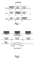
- 1 shows a simplified example of the communication schedule of a communication network with the three network nodes 1, 2 and 3, the three network nodes only going to may send the specified times t1, t2 and t3.
- Fig. 2 shows the relationship between a communication schedule Communication controller and the monitoring schedule of an assigned Bus guardian.
- the time span for node n is shown is assigned to node n for transmission according to the communication schedule.
- the bus guard opens a little earlier and closes a little later, each offset by a tolerance window.
- Fig. 3 shows a simplified time division scheme with two communication nodes and a communication cycle consisting of 8 data packets (frames).
- This Example shows that the transmission times of the both nodes can drift so that at the end of the communication cycle there is a risk of collision consists.
- the collisions can be caused by "inter frame gaps "can be prevented. It can be seen that only once at the beginning of each communication cycle all nodes synchronized by receiving a special symbol and, as a result, larger deviations occur with increasing cycle length.
- the length of the "inter frame gap” is used as a constant parameter for the entire duration of the Communication cycle set and cannot be dynamic at the end of the cycle be enlarged.
- Fig. 4 shows an example of a network node in which the bus guardian due to deviating Clock frequency drifts away in the course of a communication cycle.
- the bus guardian shows at the beginning of the communication cycle correct timing, but always deviates in the second half of the cycle more depending on the transmission times of the communication controller. From the fifth If the bus guardian is closed too early, data packets will even become part of the data packets cut off. The only remedy would be to enlarge the "inter frame gaps" possible.
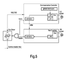
- Fig. 5 shows the basic structure of a bus guardian and its connection to one Communication controller according to the state of the art.
- the Bus guard only once at the beginning of the communication cycle using the ARM signal synchronized by the communication controller and then runs freely with the Accuracy of its own clock oscillator until the end of the cycle. It means that clock deviations between communication controller and bus guardian up to At the end of the communication cycle it may be possible to add up in such a way that the Bus guardian can no longer perform his task without errors.
- Global clock synchronization can ensure that all communication controllers have common understanding of time, but has no influence on the bus guardians, as these have their own clock oscillators for reasons of independence.
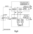
- FIG. 6 shows a section of a communication network according to the invention a communication controller and a bus guardian, which in a node of the Network are implemented and the access of the node to a data bus of the Network.
- the communication controller generates a global clock signal f_MT and a local one Clock signal f_mt.
- the bus monitor's scheduler controls the bus accesses based on the global clock signal (macrotick) f_MT.
- the two watchdog circuits WD f_MT for monitoring the macrotick and WD f_BG for monitoring the BG tick have been added and instead of the otherwise usual quartz oscillator, an integrated RC oscillator is used in this example.
- the bus guardian is continuously synchronized with the internal time of the associated communication controller, this time typically being the so-called macro tick is represented.
- the macro tick is generated from the signal of the Clock oscillator in the communication controller generated by a digital divider, its division ratio using the algorithm for global clock synchronization can be controlled that the communication controller even in the event of deviations Clock frequency adheres to the correct time division scheme. If the scheduler is now in the Bus guardian also clocked with this macro tick, so it follows the clock synchronization inserted changes in the period of the macrotick. With the help of this continuous Synchronization between communication controller and bus guardian become very narrow tolerance ranges for the opening times of the bus guardian and thus also allows short "inter-frame gaps".
- the synchronization enables a separate, precise clock oscillator for the bus guardian omitted.
- a clock signal is used as a replacement for the previous one used local clock oscillator of the bus guardian.
- This so-called BG tick is by a frequency divider directly from the clock oscillator of the communication controller is derived and is therefore independent of global clock synchronization.
- the BG tick determines the maximum resolution with which the bus guardian opens and Control the closing of the bus access.
- the BG-Tick is also required to close with the help of a watchdog circuit Check whether the period of the macrotick is within the specified tolerances. These limits are set when the system is configured and must be so be dimensioned such that permissible deviations such as those caused by clock synchronization be tolerated. If the period of the macrotick is outside the Tolerances or if the signal fails completely, the bus guardian must block bus access.
- a configurable number of periods can also be monitored. Depending on the requirements monitoring can include the entire cycle length.
- the surveillance possible by a watchdog circuit the number of BG ticks determined between two consecutive ARM signals.
- Another watchdog circuit protects against the failure or a different frequency of the BG tick signal itself. This checks in a similar way the period of the BG tick signal and thus indirectly that of the clock oscillator in the communication controller.
- a clock oscillator with relatively large tolerances is suitable as the reference oscillator, since only gross deviations from the target period have to be recognized at this point. Small deviations from the target frequency are usually recognized with the help of the algorithms for global clock synchronization in the communication controller.
- An RC oscillator can be used at this point to save costs and for easy integration.
- the bus guardian shown in Figure 6 can also be assigned to multiple nodes and control access from multiple nodes. This is particularly advantageous for star-shaped networks.
- the signal f_gw is obtained by frequency division from the clock signal of the RC oscillator.
- a gate time is defined with the aid of this signal and the number of clock periods of the BG tick signal f_BG is determined within this gate time.
- the second bus guardian WD f_MT is also built up, except that the gate time corresponds to the period of the macrotick and the number of BG ticks is counted.
- the bus guardian reacts to a failure of the RC oscillator as well as the signals f_MT and f_BG from the communication controller by blocking the bus access in the shortest possible time in order to ensure the fail-silent property of the Ensure the node also in the event of an error.
Landscapes
- Engineering & Computer Science (AREA)
- Signal Processing (AREA)
- Computer Networks & Wireless Communication (AREA)
- Small-Scale Networks (AREA)
- Synchronisation In Digital Transmission Systems (AREA)
- Time-Division Multiplex Systems (AREA)
- Computer And Data Communications (AREA)
Abstract
wobei ein Kommunikationszeitplan vorgesehen ist, der den Netzknoten Zeitschlitze für den Zugriff auf das Übertragungsmedium zuweist,
wobei die Netzknoten jeweils wenigstens einen Kommunikations-Controller mit einem ersten Zeitplaner zur Steuerung des Zugriffs der Netzknoten auf das Übertragungsmedium gemäß dem Kommunikationszeitplan aufweisen,
wobei das Kommunikationsnetzwerk wenigstens einen Buswächter mit einem zweiten Zeitplaner zur Überwachung der Zugriffe der Netzknoten auf das Übertragungsmedium gemäß einem Überwachungszeitplan aufweist,
wobei der Kommunikations-Controller Mittel zur Generierung eines lokalen, unabhängigen Taktsignals und eines globalen Taktsignals, das von wenigstens einem Parameter des Kommunikationssystems beeinflussbar ist, aufweist und
wobei das globale Taktsignal sowohl zur Steuerung der ersten Zeitplaner der Kommunikations-Controller als auch zur Steuerung des zweiten Zeitplaners des Buswächters vorgesehen ist.
Description
wobei ein Kommunikationszeitplan vorgesehen ist, der den Netzknoten Zeitschlitze für den Zugriff auf das Übertragungsmedium zuweist,
wobei die Netzknoten jeweils wenigstens einen Kommunikations-Controller mit einem ersten Zeitplaner zur Steuerung des Zugriffs der Netzknoten auf das Übertragungsmedium gemäß dem Kommunikationszeitplan aufweisen,
wobei das Kommunikationsnetzwerk wenigstens einen Buswächter mit einem zweiten Zeitplaner zur Überwachung der Zugriffe der Netzknoten auf das Übertragungsmedium gemäß einem Überwachungszeitplan aufweist,
wobei der Kommunikations-Controller Mittel zur Generierung eines lokalen, unabhängigen Taktsignals und eines globalen Taktsignals, das von wenigstens einem Parameter des Kommunikationssystems beeinflussbar ist, aufweist und
wobei das globale Taktsignal sowohl zur Steuerung der ersten Zeitplaner der Kommunikations-Controller als auch zur Steuerung des zweiten Zeitplaners des Buswächters vorgesehen ist.
Alternativ kann der in der Fig. 6 dargestellte Buswächter auch mehreren Netzknoten zugeordnet werden und den Zugriffvon mehreren Netzknoten steuern. Dies ist insbesondere bei sternförmigen Netzwerken vorteilhaft.
Claims (12)
- Kommunikationsnetzwerk mit wenigstens zwei Netzknoten, zwischen denen Daten über ein Übertragungsmedium übertragbar sind,
wobei ein Kommunikationszeitplan vorgesehen ist, der den Netzknoten Zeitschlitze für den Zugriff auf das Übertragungsmedium zuweist,
wobei die Netzknoten jeweils wenigstens einen Kommunikations-Controller mit einem ersten Zeitplaner zur Steuerung des Zugriffs der Netzknoten auf das Übertragungsmedium gemäß dem Kommunikationszeitplan aufweisen,
wobei das Kommunikationsnetzwerk wenigstens einen Buswächter mit einem zweiten Zeitplaner zur Überwachung der Zugriffe der Netzknoten auf das Übertragungsmedium gemäß einem Überwachungszeitplan aufweist,
wobei der Kommunikations-Controller Mittel zur Generierung eines lokalen, unabhängigen Taktsignals und eines globalen Taktsignals, das von wenigstens einem Parameter des Kommunikationssystems beeinflussbar ist, aufweist und
wobei das globale Taktsignal sowohl zur Steuerung der ersten Zeitplaner der Kommunikations-Controller als auch zur Steuerung des zweiten Zeitplaners des Buswächters vorgesehen ist. - Kommunikationsnetzwerk nach Anspruch 1,
dadurch gekennzeichnet, dass der Buswächter eine erste Überwachungsschaltung aufweist, welche mittels des lokalen Taktsignals des Kommunikations-Controllers das globale Taktsignal des Kommunikations-Controllers überwacht. - Kommunikationsnetzwerk nach Anspruch 1,
dadurch gekennzeichnet, dass der Buswächter einen Buswächteroszillator aufweist, welcher ein lokales Taktsignal an eine zweite Überwachungsschaltung liefert, und dass die zweite Überwachungsschaltung mittels des lokalen Taktsignals des Buswächters das lokale Taktsignal des Kommunikations-Controllers überwacht. - Kommunikationsnetzwerk nach Anspruch 3,
dadurch gekennzeichnet, dass der Buswächteroszillator ein RC-Oszillator ist. - Kommunikationsnetzwerk nach Anspruch 3,
dadurch gekennzeichnet, dass der Buswächter eine Ausfallüberwachungsschaltung aufweist, welche den Ausfall des Buswächteroszillators überwacht und dass die Ausfallüberwachungsschaltung bei Ausfall des Buswächteroszillators die Sperrung des Zugriffs der diesem Buswächter zugeordneten Knoten auf das Übertragungsmedium veranlasst oder eine Fehlermeldung generiert. - Kommunikationsnetzwerk nach Anspruch 1,
dadurch gekennzeichnet, dass in die Kommunikations-Controller des Netzwerks ein Algorithmus implementiert ist, mittels dessen die globalen Taktsignale der Kommunikations-Controller aufeinander oder in Bezug auf ein Referenzsignal abgestimmt werden. - Kommunikationsnetzwerk nach Anspruch 2,
dadurch gekennzeichnet, dass die erste Überwachungsschaltung einen Zähler aufweist, der die Anzahl der Perioden des lokalen Taktsignals über eine oder mehrere Perioden des globalen Taktsignals bestimmt und dass die erste Überwachungsschaltung die Sperrung des Zugriffs des dem Buswächter zugeordneten Knotens oder der dem Buswächter zugeordneten Knoten auf das Übertragungsmedium veranlasst, wenn die Anzahl der gezählten Perioden außerhalb eines vorgebbaren Toleranzbereiches liegt. - Kommunikationsnetzwerk nach Anspruch 3,
dadurch gekennzeichnet, dass die zweite Überwachungsschaltung einen Zähler aufweist, der die Anzahl der Perioden des lokalen Taktsignals des Kommunikations-Controllers über eine oder mehrere Perioden des lokalen Taktsignals des Buswächters bestimmt und dass die zweite Überwachungsschaltung die Sperrung des Zugriffs des dem Buswächter zugeordneten Knotens oder der dem Buswächter zugeordneten Knoten auf das Übertragungsmedium veranlasst, wenn die Anzahl der gezählten Perioden außerhalb eines vorgebbaren Toleranzbereiches liegt. - Kommunikationsnetzwerk nach Anspruch 1,
dadurch gekennzeichnet, dass die Kommunikations-Controller einen Quarzoszillator aufweisen, dass das lokale Taktsignal der Kommunikations-Controller mittels eines festen Teilers aus dem Signal des Quarzoszillators abgeleitet wird und dass das globale Taktsignal der Kommunikations-Controller mittels eines variablen Teilers aus dem Signal des Quarzoszillators abgeleitet wird, wobei das Teilerverhältnis des variablen Teilers von wenigstens einem Parameter des Kommunikationssystems beeinflussbar ist. - Kommunikations-Controller für ein Kommunikationsnetzwerk, wobei der Kommunikations-Controller mit einem ersten Zeitplaner zur Steuerung des Zugriffs eines Netzknotens auf ein Übertragungsmedium des Netzwerks gemäß einem Kommunikationszeitplan vorgesehen ist,
wobei der Kommunikations-Controller Mittel zur Generierung eines lokalen, unabhängigen Taktsignal und eines globalen Taktsignals, das von wenigstens einem Parameter des Kommunikationsnetzwerks beeinflussbar ist, aufweist,
wobei das globale Taktsignal sowohl zur Steuerung des ersten Zeitplaners des Kommunikations-Controllers als auch zur Steuerung eines zweiten Zeitplaners eines Buswächters vorgesehen ist. - Buswächter für ein Kommunikationsnetzwerk zur Überwachung des Zugriffs wenigstens eines Netzknotens auf das Übertragungsmedium gemäß einem Überwachungszeitplan, wobei der Buswächter eine erste Überwachungsschaltung aufweist, welche dazu vorgesehen ist, mittels eines lokalen Taktsignals eines Kommunikations-Controllers ein globales Taktsignal des Kommunikations-Controllers zu überwachen.
- Verfahren zur Steuerung eines Kommunikationsnetzwerk mit wenigstens zwei Netzknoten, zwischen denen Daten über ein Übertragungsmedium übertragen werden,
wobei ein Kommunikationszeitplan vorgesehen ist, der den Netzknoten Zeitschlitze für den Zugriff auf das Übertragungsmedium zuweist,
wobei die Netzknoten jeweils wenigstens einen Kommunikations-Controller mit einem ersten Zeitplaner zur Steuerung des Zugriffs der Netzknoten auf das Übertragungsmedium gemäß dem Kommunikationszeitplan aufweisen,
wobei das Kommunikationsnetzwerk wenigstens einen Buswächter mit einem zweiten Zeitplaner zur Überwachung der Zugriffe der Netzknoten auf das Übertragungsmedium gemäß einem Überwachungszeitplan aufweist,
wobei der Kommunikations-Controller ein lokales, unabhängiges Taktsignal und ein globales Taktsignal, das von wenigstens einem Parameter des Kommunikationssystems beeinflussbar ist, generiert und
wobei das globale Taktsignal sowohl die ersten Zeitplaner der Kommunikations-Controller als auch den zweiten Zeitplaner des Buswächters steuert.
Applications Claiming Priority (2)
| Application Number | Priority Date | Filing Date | Title |
|---|---|---|---|
| DE10144070 | 2001-09-07 | ||
| DE10144070A DE10144070A1 (de) | 2001-09-07 | 2001-09-07 | Kommunikationsnetzwerk und Verfahren zur Steuerung des Kommunikationsnetzwerks |
Publications (3)
| Publication Number | Publication Date |
|---|---|
| EP1292071A2 true EP1292071A2 (de) | 2003-03-12 |
| EP1292071A3 EP1292071A3 (de) | 2006-01-18 |
| EP1292071B1 EP1292071B1 (de) | 2008-03-05 |
Family
ID=7698178
Family Applications (1)
| Application Number | Title | Priority Date | Filing Date |
|---|---|---|---|
| EP02102313A Expired - Lifetime EP1292071B1 (de) | 2001-09-07 | 2002-09-05 | Kommunikationsnetzwerk und Verfahren zur Steuerung des Kommunikationsnetzwerks |
Country Status (8)
| Country | Link |
|---|---|
| US (1) | US7583692B2 (de) |
| EP (1) | EP1292071B1 (de) |
| JP (1) | JP4180332B2 (de) |
| KR (1) | KR20030022058A (de) |
| CN (1) | CN100471143C (de) |
| AT (1) | ATE388552T1 (de) |
| DE (2) | DE10144070A1 (de) |
| ES (1) | ES2300421T3 (de) |
Cited By (7)
| Publication number | Priority date | Publication date | Assignee | Title |
|---|---|---|---|---|
| WO2007054877A1 (en) * | 2005-11-10 | 2007-05-18 | Nxp B.V. | Bus guardian with improved channel monitoring |
| EP1879331A1 (de) * | 2006-07-10 | 2008-01-16 | Nissan Motor Co., Ltd. | Kommunikationsnetzwerksystem und Fehlerüberprüfungsverfahren |
| WO2008010141A1 (en) * | 2006-07-19 | 2008-01-24 | Nxp B.V. | Distributed communication system and corresponding communication method |
| US7944940B2 (en) | 2007-06-22 | 2011-05-17 | Thomson Licensing | Method and apparatus for media access in contention-based networks |
| EP2328304A1 (de) * | 2009-11-25 | 2011-06-01 | Valeo Schalter und Sensoren GmbH | Schaltungsanordnung und ein Steuergerät für sicherheitsrelevante Funktionen |
| US8037212B2 (en) | 2005-12-09 | 2011-10-11 | Ebuddy Holding B. V. | Event notification system and method |
| US8737425B2 (en) | 2007-06-22 | 2014-05-27 | Thomson Licensing | Method and apparatus for media access in contention-based networks |
Families Citing this family (38)
| Publication number | Priority date | Publication date | Assignee | Title |
|---|---|---|---|---|
| US7082136B2 (en) * | 2000-12-29 | 2006-07-25 | Net Insight Ab | Methods for controlling resources in a communication network |
| DE10148325A1 (de) * | 2001-09-29 | 2003-04-17 | Daimler Chrysler Ag | Buswächtereinheit |
| EP1355458B1 (de) * | 2002-04-16 | 2005-09-21 | ROBERT BOSCH GmbH | Verfahren zur Datenübertragung in einem Kommunikationssystem |
| US7584156B2 (en) * | 2002-05-15 | 2009-09-01 | Lockheed Martin Corporation | Method and apparatus for estimating the refresh strategy or other refresh-influenced parameters of a system over its life cycle |
| US20040010474A1 (en) * | 2002-05-15 | 2004-01-15 | Lockheed Martin Corporation | Method and apparatus for estimating the refresh strategy or other refresh-influenced parameters of a system over its life cycle |
| FR2845545B1 (fr) * | 2002-10-07 | 2005-02-04 | Alstom | Procede d'echange securitaire de messages d'information |
| SE524201C2 (sv) * | 2002-12-17 | 2004-07-06 | Lars-Berno Fredriksson | Anordning vid distribuerat styr- och övervakningssystem |
| ATE365410T1 (de) * | 2003-05-05 | 2007-07-15 | Koninkl Philips Electronics Nv | Fehlererkennung und unterdrückung in einem tdma- basierten netzknoten |
| EP1622794A1 (de) * | 2003-05-06 | 2006-02-08 | Philips Intellectual Property & Standards GmbH | Zeitschlitzteilung über mehrere zyklen in einem tdma bus |
| GB2404827A (en) * | 2003-08-05 | 2005-02-09 | Motorola Inc | Fault containment at non-faulty processing nodes in TDMA networks |
| AT500350B8 (de) * | 2003-10-03 | 2007-02-15 | Bernecker & Rainer Ind Elektro | Anlage zum übertragen von daten in einem seriellen, bidirektionalen bus |
| EP1690377A2 (de) * | 2003-11-19 | 2006-08-16 | Honeywell International Inc. | Auf prioritäten basierende arbitrierung für die tdma-einteilungsdurchsetzung in einem mehrkanaligen system in sternkonfiguration |
| JP2007511987A (ja) * | 2003-11-19 | 2007-05-10 | ハネウェル・インターナショナル・インコーポレーテッド | 集中通信ガーディアンの寄生時間同期化 |
| JP4848027B2 (ja) * | 2004-01-30 | 2011-12-28 | 日立オートモティブシステムズ株式会社 | 車両制御装置 |
| US20080285507A1 (en) * | 2004-04-28 | 2008-11-20 | Nortel Networks Limited | Independent Scheduling in a Wireless Network |
| US20060217929A1 (en) * | 2004-08-06 | 2006-09-28 | Lockheed Martin Corporation | Lifetime support process for rapidly changing, technology-intensive systems |
| JP2008524903A (ja) * | 2004-12-20 | 2008-07-10 | エヌエックスピー ビー ヴィ | 複数のノード間の通信を監視するバスガーディアン及び方法、そのようなバスガーディアンを具えるノード並びにそのようなノードを具える分散通信システム |
| EP1860804B1 (de) * | 2006-05-23 | 2012-09-12 | Alcatel Lucent | Vorbehandelungsverfahren zur Gewinnregelung eines Verstärkers, optisches Zugangsnetz, Zentralstation und Endstation |
| US7430692B2 (en) * | 2006-06-16 | 2008-09-30 | Siemens Medical Solutions Usa, Inc. | Processor operational status management system |
| US9008002B2 (en) | 2006-08-07 | 2015-04-14 | Qualcomm Incorporated | Conditional requests for asynchronous wireless communication |
| CN101632262B (zh) * | 2007-03-14 | 2012-05-23 | Nxp股份有限公司 | 分布式通信系统的节点、连接到通信系统的节点及监测装置 |
| EP2193444A2 (de) * | 2007-09-03 | 2010-06-09 | Nxp B.V. | Taktüberwachungseinheit |
| US8407339B2 (en) * | 2007-11-14 | 2013-03-26 | Nxp B.V. | Star network and method for preventing a repeated transmission of a control symbol in such a star network |
| KR100967996B1 (ko) * | 2008-02-15 | 2010-07-07 | 사천시농업기술센터 | 꿀벌 응애 구제기 |
| ATE515859T1 (de) * | 2008-03-03 | 2011-07-15 | Sick Ag | Redundantes feldbussystem |
| EP2241952A1 (de) * | 2009-04-17 | 2010-10-20 | Siemens Aktiengesellschaft | Verfahren zur Überprüfung einer Datenverarbeitungseinrichtung auf die Eignung zur Durchführung fehlersicherer Automatisierungsabläufe |
| DE102009030204A1 (de) * | 2009-06-24 | 2010-12-30 | Audi Ag | Sternkoppler für ein Bussystem, Bussystem mit einem solchen Sternkoppler sowie Verfahren zum Austauschen von Signalen in einem Bussystem |
| WO2011067809A1 (ja) * | 2009-12-02 | 2011-06-09 | トヨタ自動車株式会社 | データ通信ネットワークシステム |
| GB201007068D0 (en) * | 2010-04-28 | 2010-06-09 | Tte Systems Ltd | Non invasive safety wrapper for computer systems |
| DE102010036457B4 (de) * | 2010-07-16 | 2017-12-14 | Dr. Ing. H.C. F. Porsche Aktiengesellschaft | Verfahren zur Ermittlung von Kommunikationsabsatzpunkten |
| DE102011016706A1 (de) | 2011-04-11 | 2012-10-11 | Conti Temic Microelectronic Gmbh | Schaltungsanordnung mit Fail-Silent-Funktion |
| US8856415B2 (en) * | 2012-02-01 | 2014-10-07 | National Instruments Corporation | Bus arbitration for a real-time computer system |
| KR101558084B1 (ko) * | 2014-04-15 | 2015-10-06 | 엘에스산전 주식회사 | 복수의 cpu 모듈을 구비하는 plc 시스템 및 제어방법 |
| FR3036241B1 (fr) * | 2015-05-12 | 2017-06-02 | Peugeot Citroen Automobiles Sa | Procede et dispositif de controle de la transmission de trames dans un reseau video bidirectionnel |
| CN107040327B (zh) * | 2017-06-14 | 2019-04-02 | 深圳市华信天线技术有限公司 | 主从机tdma时隙同步校准方法及装置 |
| DE102018101103A1 (de) * | 2018-01-18 | 2019-07-18 | Volkswagen Aktiengesellschaft | Verfahren und Computerprogramme für eine Überwachungsinstanz und eine Kommunikationskomponente, Überwachungsinstanz, Kommunikationskomponente, System und Fahrzeug |
| EP3902206B1 (de) * | 2020-04-21 | 2022-02-16 | TTTech Computertechnik Aktiengesellschaft | Fehlertolerante verteilereinheit und verfahren zur bereitstellung einer fehlertoleranten globalen zeit |
| JP7248044B2 (ja) * | 2021-02-26 | 2023-03-29 | 株式会社安川電機 | コントローラ、機器制御システム、時刻同期方法、および時刻同期プログラム |
Family Cites Families (16)
| Publication number | Priority date | Publication date | Assignee | Title |
|---|---|---|---|---|
| AT382253B (de) * | 1984-06-22 | 1987-02-10 | Austria Mikrosysteme Int | Lose gekoppeltes verteiltes computersystem |
| DE4140017C2 (de) * | 1991-12-04 | 1995-01-05 | Nec Electronics Germany | Verfahren zum Betreiben von über einen Datenbus durch seriellen Datenaustausch miteinander kommunizierenden Rechnereinheiten |
| US5481573A (en) * | 1992-06-26 | 1996-01-02 | International Business Machines Corporation | Synchronous clock distribution system |
| KR950005940B1 (ko) * | 1992-12-29 | 1995-06-07 | 재단법인한국전자통신연구소 | 클럭 감시 회로 |
| KR950005940A (ko) * | 1993-08-18 | 1995-03-20 | 김학기 | 항균체를 함유한 장갑 |
| JP2980304B2 (ja) * | 1994-07-06 | 1999-11-22 | 沖電気工業株式会社 | クロック障害検出回路 |
| DE19509558A1 (de) * | 1995-03-16 | 1996-09-19 | Abb Patent Gmbh | Verfahren zur fehlertoleranten Kommunikation unter hohen Echtzeitbedingungen |
| US5694542A (en) * | 1995-11-24 | 1997-12-02 | Fault Tolerant Systems Fts-Computertechnik Ges.M.B. | Time-triggered communication control unit and communication method |
| US5737212A (en) * | 1995-12-04 | 1998-04-07 | Industrial Technology Research Institute | Flag setting circuit for microcontroller |
| DE19627362C2 (de) * | 1996-07-06 | 1998-11-26 | Bosch Gmbh Robert | Schaltung zur Initialisierung und Überwachung eines Mikroprozessors |
| US6133750A (en) * | 1998-04-27 | 2000-10-17 | Lattice Semiconductor Corp. | Combination of global clock and localized clocks |
| US6550017B1 (en) * | 1999-06-29 | 2003-04-15 | Sun Microsystems, Inc. | System and method of monitoring a distributed fault tolerant computer system |
| DE19947657A1 (de) * | 1999-10-04 | 2001-04-12 | Bayerische Motoren Werke Ag | Betriebsverfahren für einen Datenbus für mehrere Teilnehmer mit flexiblem zeitgesteuertem Zugriff |
| DE10000302B4 (de) * | 2000-01-05 | 2011-08-11 | Robert Bosch GmbH, 70469 | Verfahren und Vorrichtung zum Austausch von Daten zwischen wenigstens zwei mit einem Bussystem verbundenen Teilnehmern |
| AT410490B (de) * | 2000-10-10 | 2003-05-26 | Fts Computertechnik Gmbh | Verfahren zur tolerierung von ''slightly-off- specification'' fehlern in einem verteilten fehlertoleranten echtzeitcomputersystem |
| EP1280024B1 (de) * | 2001-07-26 | 2009-04-01 | Freescale Semiconductor, Inc. | Uhrensynchronisation in einem verteilten System |
-
2001
- 2001-09-07 DE DE10144070A patent/DE10144070A1/de not_active Withdrawn
-
2002
- 2002-09-04 CN CNB02154543XA patent/CN100471143C/zh not_active Expired - Fee Related
- 2002-09-05 ES ES02102313T patent/ES2300421T3/es not_active Expired - Lifetime
- 2002-09-05 DE DE50211816T patent/DE50211816D1/de not_active Expired - Lifetime
- 2002-09-05 EP EP02102313A patent/EP1292071B1/de not_active Expired - Lifetime
- 2002-09-05 AT AT02102313T patent/ATE388552T1/de not_active IP Right Cessation
- 2002-09-06 KR KR1020020053684A patent/KR20030022058A/ko not_active Abandoned
- 2002-09-06 US US10/236,179 patent/US7583692B2/en active Active
- 2002-09-09 JP JP2002263177A patent/JP4180332B2/ja not_active Expired - Fee Related
Cited By (26)
| Publication number | Priority date | Publication date | Assignee | Title |
|---|---|---|---|---|
| WO2007054877A1 (en) * | 2005-11-10 | 2007-05-18 | Nxp B.V. | Bus guardian with improved channel monitoring |
| US9250984B2 (en) | 2005-12-09 | 2016-02-02 | Ebuddy Holding B.V. | Message history display system and method |
| US11438293B2 (en) | 2005-12-09 | 2022-09-06 | Ebuddy Holding B.V. | Title provisioning for event notification on a mobile device |
| US12244555B2 (en) | 2005-12-09 | 2025-03-04 | Ebuddy Technologies B.V. | Message history display system and method |
| US12021810B2 (en) | 2005-12-09 | 2024-06-25 | Ebuddy Technologies B.V. | Title provisioning for event notification on a mobile device |
| US8037212B2 (en) | 2005-12-09 | 2011-10-11 | Ebuddy Holding B. V. | Event notification system and method |
| US8230135B2 (en) | 2005-12-09 | 2012-07-24 | Ebuddy Holding B.V. | Event notification system and method |
| US8356070B2 (en) | 2005-12-09 | 2013-01-15 | Ebuddy Holding B.V. | High level network layer system and method |
| US8510395B2 (en) | 2005-12-09 | 2013-08-13 | Ebuddy Holding B.V. | Contact list display system and method |
| US8700713B2 (en) | 2005-12-09 | 2014-04-15 | Ebuddy Holding B.V. | Picture provisioning system and method |
| US11689489B2 (en) | 2005-12-09 | 2023-06-27 | Ebuddy Technologies B.V. | Message history display system and method |
| US8806084B2 (en) | 2005-12-09 | 2014-08-12 | Ebuddy Holding B.V. | Event notification system and method |
| USRE46328E1 (en) | 2005-12-09 | 2017-02-28 | Ebuddy Holding B.V. | Event notification system and method |
| US11438291B2 (en) | 2005-12-09 | 2022-09-06 | Ebuddy Holding B.V. | Message history display system and method |
| US10389666B2 (en) | 2005-12-09 | 2019-08-20 | Ebuddy Technologies B.V. | Event notification |
| US9584453B2 (en) | 2005-12-09 | 2017-02-28 | Ebuddy Holding B.V. | Contact list aggregation and display |
| US10523612B2 (en) | 2005-12-09 | 2019-12-31 | Ebuddy Technologies B.V. | Message history display system and method |
| US10536412B2 (en) | 2005-12-09 | 2020-01-14 | Ebuddy Technologies B.V. | Contact list aggregation and display |
| US10735364B2 (en) | 2005-12-09 | 2020-08-04 | Ebuddy Technologies B.V. | Title provisioning for event notification on a mobile device |
| US10986057B2 (en) | 2005-12-09 | 2021-04-20 | Ebuddy Technologies B.V. | Message history display system and method |
| US11012393B2 (en) | 2005-12-09 | 2021-05-18 | Ebuddy Technologies B.V. | Contact list aggregation and display |
| EP1879331A1 (de) * | 2006-07-10 | 2008-01-16 | Nissan Motor Co., Ltd. | Kommunikationsnetzwerksystem und Fehlerüberprüfungsverfahren |
| WO2008010141A1 (en) * | 2006-07-19 | 2008-01-24 | Nxp B.V. | Distributed communication system and corresponding communication method |
| US8737425B2 (en) | 2007-06-22 | 2014-05-27 | Thomson Licensing | Method and apparatus for media access in contention-based networks |
| US7944940B2 (en) | 2007-06-22 | 2011-05-17 | Thomson Licensing | Method and apparatus for media access in contention-based networks |
| EP2328304A1 (de) * | 2009-11-25 | 2011-06-01 | Valeo Schalter und Sensoren GmbH | Schaltungsanordnung und ein Steuergerät für sicherheitsrelevante Funktionen |
Also Published As
| Publication number | Publication date |
|---|---|
| EP1292071B1 (de) | 2008-03-05 |
| EP1292071A3 (de) | 2006-01-18 |
| JP4180332B2 (ja) | 2008-11-12 |
| CN1417983A (zh) | 2003-05-14 |
| JP2003198498A (ja) | 2003-07-11 |
| DE10144070A1 (de) | 2003-03-27 |
| US7583692B2 (en) | 2009-09-01 |
| CN100471143C (zh) | 2009-03-18 |
| ES2300421T3 (es) | 2008-06-16 |
| US20030067873A1 (en) | 2003-04-10 |
| ATE388552T1 (de) | 2008-03-15 |
| DE50211816D1 (de) | 2008-04-17 |
| KR20030022058A (ko) | 2003-03-15 |
Similar Documents
| Publication | Publication Date | Title |
|---|---|---|
| EP1292071B1 (de) | Kommunikationsnetzwerk und Verfahren zur Steuerung des Kommunikationsnetzwerks | |
| EP1471433B1 (de) | Verfahren und Vorrichtung zur Synchronisation der globalen Zeit von mehreren Bussen sowie entsprechendes Bussystem | |
| EP1756986B1 (de) | Verfahren zur etablierung einer globalen zeitbasis in einem zeitgesteuerten kommunikationssystem und kommunikationssystem | |
| DE10206875A1 (de) | Verfahren und Schaltungsanordnung zum Überwachen und Verwalten des Datenverkehrs in einem Kommunikationssystem mit mehreren Kommunikationsknoten | |
| EP4078863B1 (de) | Verfahren zur prüfung der gültigkeit von sensordaten eines ethernet-bordnetzes | |
| DE10148325A1 (de) | Buswächtereinheit | |
| EP2263347A1 (de) | Kommunikationssystem umfassend einen datenbus und mehrere daran angeschlossene teilnehmerknoten sowie verfahren zum betreiben eines solchen kommunikationssystems | |
| EP4078921B1 (de) | Verfahren zur absicherung der zeitsynchronisation eines ethernet-bordnetzes | |
| DE102005061392A1 (de) | Bus-Guardian eines Teilnehmers eines Kommunikationssystems, sowie Teilnehmer für ein Kommunikationssystem | |
| EP4256730B1 (de) | Verfahren zur ermittlung der steuergerätetemperatur durch ein zeitsynchronisationsprotokoll | |
| EP1639758B1 (de) | Verfahren und vorrichtung zum austausch von daten über ein bussystem | |
| DE19912556A1 (de) | Drahtloses Netzwerk mit einer Anwendertaktsynchronisation | |
| EP1495590B1 (de) | Netzwerk mit einem verbindungs-netzwerk and mehreren mit dem verbindungs-netzwerk gekoppelten netzknoten | |
| WO2007074057A1 (de) | Überwachungseinheit zur überwachung oder steuerung des zugriffs eines teilnehmers auf einen datenbus und teilnehmer mit einer solchen überwachungseinheit | |
| WO2020069815A1 (de) | Aggregatorvorrichtung für einen vereinheitlichten zugriff auf eine mehrzahl von netzwerksegmenten eines feldbussystems | |
| DE69106570T2 (de) | Dynamische Schaltungsanordnung zur Fehlermaskierung in einem System mit Verdoppelung des digitalen Kanals. | |
| DE102005060903A1 (de) | Verfahren und Vorrichtung zum Dekodieren eines Signals | |
| DE20121466U1 (de) | Taktsynchronisation in einem verteilen System | |
| EP3028409B1 (de) | Filtern eines datenpaketes durch eine netzwerkfiltereinrichtung | |
| DE10053525A1 (de) | Verfahren und System zur Synchronisation von Teilnehmern einer Kommunikationsverbindung | |
| DE102018213198A1 (de) | Verfahren zum Überwachen der Kommunikation eines Bussystems eines Fahrzeugs | |
| DE10032597B4 (de) | Buswächtereinheit für einen Netzknoten eines zeitgetriggerten Datenkommunikationsnetzes | |
| EP1497735B1 (de) | Verfahren und vorrichtung zur überprufung einer überwachungsfunktion eines bussystems und bussystem | |
| EP3699705A1 (de) | Verfahren zur überwachung eines industriellen kommunikationsnetzwerkes, sicherheits-system, industrielles kommunikationsnetzwerk, computerprogramm und computerlesbares medium | |
| DE102005014775B4 (de) | Verfahren, Kommunikationsanordnung und Kommunikationseinrichtung zur Steuerung des Zugriffs auf zumindest eine Kommunikationseinrichtung |
Legal Events
| Date | Code | Title | Description |
|---|---|---|---|
| PUAI | Public reference made under article 153(3) epc to a published international application that has entered the european phase |
Free format text: ORIGINAL CODE: 0009012 |
|
| AK | Designated contracting states |
Kind code of ref document: A2 Designated state(s): AT BE BG CH CY CZ DE DK EE ES FI FR GB GR IE IT LI LU MC NL PT SE SK TR |
|
| AX | Request for extension of the european patent |
Extension state: AL LT LV MK RO SI |
|
| RAP1 | Party data changed (applicant data changed or rights of an application transferred) |
Owner name: KONINKLIJKE PHILIPS ELECTRONICS N.V. Owner name: PHILIPS INTELLECTUAL PROPERTY & STANDARDS GMBH |
|
| PUAL | Search report despatched |
Free format text: ORIGINAL CODE: 0009013 |
|
| AK | Designated contracting states |
Kind code of ref document: A3 Designated state(s): AT BE BG CH CY CZ DE DK EE ES FI FR GB GR IE IT LI LU MC NL PT SE SK TR |
|
| AX | Request for extension of the european patent |
Extension state: AL LT LV MK RO SI |
|
| 17P | Request for examination filed |
Effective date: 20060718 |
|
| AKX | Designation fees paid |
Designated state(s): AT BE BG CH CY CZ DE DK EE ES FI FR GB GR IE IT LI LU MC NL PT SE SK TR |
|
| 17Q | First examination report despatched |
Effective date: 20060912 |
|
| RAP1 | Party data changed (applicant data changed or rights of an application transferred) |
Owner name: NXP B.V. Owner name: PHILIPS INTELLECTUAL PROPERTY & STANDARDS GMBH |
|
| GRAP | Despatch of communication of intention to grant a patent |
Free format text: ORIGINAL CODE: EPIDOSNIGR1 |
|
| GRAS | Grant fee paid |
Free format text: ORIGINAL CODE: EPIDOSNIGR3 |
|
| GRAA | (expected) grant |
Free format text: ORIGINAL CODE: 0009210 |
|
| AK | Designated contracting states |
Kind code of ref document: B1 Designated state(s): AT BE BG CH CY CZ DE DK EE ES FI FR GB GR IE IT LI LU MC NL PT SE SK TR |
|
| REG | Reference to a national code |
Ref country code: GB Ref legal event code: FG4D Free format text: NOT ENGLISH |
|
| REG | Reference to a national code |
Ref country code: CH Ref legal event code: EP |
|
| REG | Reference to a national code |
Ref country code: IE Ref legal event code: FG4D Free format text: LANGUAGE OF EP DOCUMENT: GERMAN |
|
| REF | Corresponds to: |
Ref document number: 50211816 Country of ref document: DE Date of ref document: 20080417 Kind code of ref document: P |
|
| GBT | Gb: translation of ep patent filed (gb section 77(6)(a)/1977) |
Effective date: 20080413 |
|
| REG | Reference to a national code |
Ref country code: ES Ref legal event code: FG2A Ref document number: 2300421 Country of ref document: ES Kind code of ref document: T3 |
|
| PG25 | Lapsed in a contracting state [announced via postgrant information from national office to epo] |
Ref country code: FI Free format text: LAPSE BECAUSE OF FAILURE TO SUBMIT A TRANSLATION OF THE DESCRIPTION OR TO PAY THE FEE WITHIN THE PRESCRIBED TIME-LIMIT Effective date: 20080305 |
|
| NLV1 | Nl: lapsed or annulled due to failure to fulfill the requirements of art. 29p and 29m of the patents act | ||
| REG | Reference to a national code |
Ref country code: IE Ref legal event code: FD4D |
|
| PG25 | Lapsed in a contracting state [announced via postgrant information from national office to epo] |
Ref country code: SK Free format text: LAPSE BECAUSE OF FAILURE TO SUBMIT A TRANSLATION OF THE DESCRIPTION OR TO PAY THE FEE WITHIN THE PRESCRIBED TIME-LIMIT Effective date: 20080305 Ref country code: CZ Free format text: LAPSE BECAUSE OF FAILURE TO SUBMIT A TRANSLATION OF THE DESCRIPTION OR TO PAY THE FEE WITHIN THE PRESCRIBED TIME-LIMIT Effective date: 20080305 Ref country code: SE Free format text: LAPSE BECAUSE OF FAILURE TO SUBMIT A TRANSLATION OF THE DESCRIPTION OR TO PAY THE FEE WITHIN THE PRESCRIBED TIME-LIMIT Effective date: 20080605 Ref country code: NL Free format text: LAPSE BECAUSE OF FAILURE TO SUBMIT A TRANSLATION OF THE DESCRIPTION OR TO PAY THE FEE WITHIN THE PRESCRIBED TIME-LIMIT Effective date: 20080305 Ref country code: PT Free format text: LAPSE BECAUSE OF FAILURE TO SUBMIT A TRANSLATION OF THE DESCRIPTION OR TO PAY THE FEE WITHIN THE PRESCRIBED TIME-LIMIT Effective date: 20080805 |
|
| RAP2 | Party data changed (patent owner data changed or rights of a patent transferred) |
Owner name: NXP B.V. |
|
| ET | Fr: translation filed | ||
| PLBE | No opposition filed within time limit |
Free format text: ORIGINAL CODE: 0009261 |
|
| STAA | Information on the status of an ep patent application or granted ep patent |
Free format text: STATUS: NO OPPOSITION FILED WITHIN TIME LIMIT |
|
| PG25 | Lapsed in a contracting state [announced via postgrant information from national office to epo] |
Ref country code: DK Free format text: LAPSE BECAUSE OF FAILURE TO SUBMIT A TRANSLATION OF THE DESCRIPTION OR TO PAY THE FEE WITHIN THE PRESCRIBED TIME-LIMIT Effective date: 20080305 Ref country code: IE Free format text: LAPSE BECAUSE OF FAILURE TO SUBMIT A TRANSLATION OF THE DESCRIPTION OR TO PAY THE FEE WITHIN THE PRESCRIBED TIME-LIMIT Effective date: 20080305 |
|
| 26N | No opposition filed |
Effective date: 20081208 |
|
| PG25 | Lapsed in a contracting state [announced via postgrant information from national office to epo] |
Ref country code: MC Free format text: LAPSE BECAUSE OF NON-PAYMENT OF DUE FEES Effective date: 20080930 Ref country code: BG Free format text: LAPSE BECAUSE OF FAILURE TO SUBMIT A TRANSLATION OF THE DESCRIPTION OR TO PAY THE FEE WITHIN THE PRESCRIBED TIME-LIMIT Effective date: 20080605 Ref country code: EE Free format text: LAPSE BECAUSE OF FAILURE TO SUBMIT A TRANSLATION OF THE DESCRIPTION OR TO PAY THE FEE WITHIN THE PRESCRIBED TIME-LIMIT Effective date: 20080305 |
|
| REG | Reference to a national code |
Ref country code: CH Ref legal event code: PL |
|
| PG25 | Lapsed in a contracting state [announced via postgrant information from national office to epo] |
Ref country code: CY Free format text: LAPSE BECAUSE OF FAILURE TO SUBMIT A TRANSLATION OF THE DESCRIPTION OR TO PAY THE FEE WITHIN THE PRESCRIBED TIME-LIMIT Effective date: 20080305 |
|
| PG25 | Lapsed in a contracting state [announced via postgrant information from national office to epo] |
Ref country code: CH Free format text: LAPSE BECAUSE OF NON-PAYMENT OF DUE FEES Effective date: 20080930 Ref country code: LI Free format text: LAPSE BECAUSE OF NON-PAYMENT OF DUE FEES Effective date: 20080930 Ref country code: AT Free format text: LAPSE BECAUSE OF NON-PAYMENT OF DUE FEES Effective date: 20080905 |
|
| PG25 | Lapsed in a contracting state [announced via postgrant information from national office to epo] |
Ref country code: LU Free format text: LAPSE BECAUSE OF NON-PAYMENT OF DUE FEES Effective date: 20080905 |
|
| PG25 | Lapsed in a contracting state [announced via postgrant information from national office to epo] |
Ref country code: TR Free format text: LAPSE BECAUSE OF FAILURE TO SUBMIT A TRANSLATION OF THE DESCRIPTION OR TO PAY THE FEE WITHIN THE PRESCRIBED TIME-LIMIT Effective date: 20080305 |
|
| PG25 | Lapsed in a contracting state [announced via postgrant information from national office to epo] |
Ref country code: GR Free format text: LAPSE BECAUSE OF FAILURE TO SUBMIT A TRANSLATION OF THE DESCRIPTION OR TO PAY THE FEE WITHIN THE PRESCRIBED TIME-LIMIT Effective date: 20080606 |
|
| REG | Reference to a national code |
Ref country code: FR Ref legal event code: TP Owner name: PHILIPS INTELLECTUAL PROPERTY & STANDARDS, DE Effective date: 20120809 |
|
| REG | Reference to a national code |
Ref country code: GB Ref legal event code: 732E Free format text: REGISTERED BETWEEN 20120816 AND 20120822 |
|
| REG | Reference to a national code |
Ref country code: FR Ref legal event code: TP Owner name: NXP B.V., NL Effective date: 20121011 |
|
| PGFP | Annual fee paid to national office [announced via postgrant information from national office to epo] |
Ref country code: IT Payment date: 20120724 Year of fee payment: 11 Ref country code: BE Payment date: 20120724 Year of fee payment: 11 Ref country code: ES Payment date: 20120727 Year of fee payment: 11 |
|
| REG | Reference to a national code |
Ref country code: DE Ref legal event code: R081 Ref document number: 50211816 Country of ref document: DE Owner name: PARTNERS FOR CORPORATE RESEARCH CV, KY Free format text: FORMER OWNER: NXP B.V., PHILIPS INTELLECTUAL PROPERTY &, , NL Effective date: 20130322 Ref country code: DE Ref legal event code: R081 Ref document number: 50211816 Country of ref document: DE Owner name: PARTNERS FOR CORPORATE RESEARCH CV, GEORGE TOW, KY Free format text: FORMER OWNER: NXP B.V., PHILIPS INTELLECTUAL PROPERTY &, , NL Effective date: 20130322 Ref country code: DE Ref legal event code: R081 Ref document number: 50211816 Country of ref document: DE Owner name: PARTNERS FOR CORPORATE RESEARCH CV, GEORGE TOW, KY Free format text: FORMER OWNERS: NXP B.V., EINDHOVEN, NL; PHILIPS INTELLECTUAL PROPERTY & STANDARDS GMBH, 20099 HAMBURG, DE Effective date: 20130322 |
|
| BERE | Be: lapsed |
Owner name: NXP B.V. Effective date: 20130930 Owner name: PHILIPS INTELLECTUAL PROPERTY & STANDARDS G.M.B.H. Effective date: 20130930 |
|
| PG25 | Lapsed in a contracting state [announced via postgrant information from national office to epo] |
Ref country code: BE Free format text: LAPSE BECAUSE OF NON-PAYMENT OF DUE FEES Effective date: 20130930 |
|
| PG25 | Lapsed in a contracting state [announced via postgrant information from national office to epo] |
Ref country code: IT Free format text: LAPSE BECAUSE OF NON-PAYMENT OF DUE FEES Effective date: 20130905 |
|
| PGFP | Annual fee paid to national office [announced via postgrant information from national office to epo] |
Ref country code: GB Payment date: 20140903 Year of fee payment: 13 |
|
| PGFP | Annual fee paid to national office [announced via postgrant information from national office to epo] |
Ref country code: FR Payment date: 20140906 Year of fee payment: 13 |
|
| REG | Reference to a national code |
Ref country code: ES Ref legal event code: FD2A Effective date: 20150504 |
|
| PG25 | Lapsed in a contracting state [announced via postgrant information from national office to epo] |
Ref country code: ES Free format text: LAPSE BECAUSE OF NON-PAYMENT OF DUE FEES Effective date: 20130906 |
|
| GBPC | Gb: european patent ceased through non-payment of renewal fee |
Effective date: 20150905 |
|
| REG | Reference to a national code |
Ref country code: FR Ref legal event code: ST Effective date: 20160531 |
|
| PG25 | Lapsed in a contracting state [announced via postgrant information from national office to epo] |
Ref country code: GB Free format text: LAPSE BECAUSE OF NON-PAYMENT OF DUE FEES Effective date: 20150905 |
|
| PG25 | Lapsed in a contracting state [announced via postgrant information from national office to epo] |
Ref country code: FR Free format text: LAPSE BECAUSE OF NON-PAYMENT OF DUE FEES Effective date: 20150930 |
|
| PGFP | Annual fee paid to national office [announced via postgrant information from national office to epo] |
Ref country code: DE Payment date: 20170928 Year of fee payment: 16 |
|
| REG | Reference to a national code |
Ref country code: DE Ref legal event code: R119 Ref document number: 50211816 Country of ref document: DE |
|
| PG25 | Lapsed in a contracting state [announced via postgrant information from national office to epo] |
Ref country code: DE Free format text: LAPSE BECAUSE OF NON-PAYMENT OF DUE FEES Effective date: 20190402 |