EP1291991A2 - Procédé d'installation d'un élément tubulaire dans une cavité inaccessible à un opérateur - Google Patents
Procédé d'installation d'un élément tubulaire dans une cavité inaccessible à un opérateur Download PDFInfo
- Publication number
- EP1291991A2 EP1291991A2 EP02292133A EP02292133A EP1291991A2 EP 1291991 A2 EP1291991 A2 EP 1291991A2 EP 02292133 A EP02292133 A EP 02292133A EP 02292133 A EP02292133 A EP 02292133A EP 1291991 A2 EP1291991 A2 EP 1291991A2
- Authority
- EP
- European Patent Office
- Prior art keywords
- holding
- tubular element
- cavity
- wall
- internal wall
- Prior art date
- Legal status (The legal status is an assumption and is not a legal conclusion. Google has not performed a legal analysis and makes no representation as to the accuracy of the status listed.)
- Withdrawn
Links
Images


Classifications
-
- H—ELECTRICITY
- H02—GENERATION; CONVERSION OR DISTRIBUTION OF ELECTRIC POWER
- H02G—INSTALLATION OF ELECTRIC CABLES OR LINES, OR OF COMBINED OPTICAL AND ELECTRIC CABLES OR LINES
- H02G1/00—Methods or apparatus specially adapted for installing, maintaining, repairing or dismantling electric cables or lines
- H02G1/06—Methods or apparatus specially adapted for installing, maintaining, repairing or dismantling electric cables or lines for laying cables, e.g. laying apparatus on vehicle
- H02G1/08—Methods or apparatus specially adapted for installing, maintaining, repairing or dismantling electric cables or lines for laying cables, e.g. laying apparatus on vehicle through tubing or conduit, e.g. rod or draw wire for pushing or pulling
- H02G1/086—Methods or apparatus specially adapted for installing, maintaining, repairing or dismantling electric cables or lines for laying cables, e.g. laying apparatus on vehicle through tubing or conduit, e.g. rod or draw wire for pushing or pulling using fluid as pulling means, e.g. liquid, pressurised gas or suction means
-
- B—PERFORMING OPERATIONS; TRANSPORTING
- B08—CLEANING
- B08B—CLEANING IN GENERAL; PREVENTION OF FOULING IN GENERAL
- B08B9/00—Cleaning hollow articles by methods or apparatus specially adapted thereto
- B08B9/02—Cleaning pipes or tubes or systems of pipes or tubes
- B08B9/027—Cleaning the internal surfaces; Removal of blockages
- B08B9/04—Cleaning the internal surfaces; Removal of blockages using cleaning devices introduced into and moved along the pipes
- B08B9/049—Cleaning the internal surfaces; Removal of blockages using cleaning devices introduced into and moved along the pipes having self-contained propelling means for moving the cleaning devices along the pipes, i.e. self-propelled
- B08B9/0495—Nozzles propelled by fluid jets
-
- F—MECHANICAL ENGINEERING; LIGHTING; HEATING; WEAPONS; BLASTING
- F16—ENGINEERING ELEMENTS AND UNITS; GENERAL MEASURES FOR PRODUCING AND MAINTAINING EFFECTIVE FUNCTIONING OF MACHINES OR INSTALLATIONS; THERMAL INSULATION IN GENERAL
- F16L—PIPES; JOINTS OR FITTINGS FOR PIPES; SUPPORTS FOR PIPES, CABLES OR PROTECTIVE TUBING; MEANS FOR THERMAL INSULATION IN GENERAL
- F16L7/00—Supporting of pipes or cables inside other pipes or sleeves, e.g. for enabling pipes or cables to be inserted or withdrawn from under roads or railways without interruption of traffic
-
- G—PHYSICS
- G02—OPTICS
- G02B—OPTICAL ELEMENTS, SYSTEMS OR APPARATUS
- G02B6/00—Light guides; Structural details of arrangements comprising light guides and other optical elements, e.g. couplings
- G02B6/46—Processes or apparatus adapted for installing or repairing optical fibres or optical cables
- G02B6/50—Underground or underwater installation; Installation through tubing, conduits or ducts
- G02B6/52—Underground or underwater installation; Installation through tubing, conduits or ducts using fluid, e.g. air
-
- H—ELECTRICITY
- H02—GENERATION; CONVERSION OR DISTRIBUTION OF ELECTRIC POWER
- H02G—INSTALLATION OF ELECTRIC CABLES OR LINES, OR OF COMBINED OPTICAL AND ELECTRIC CABLES OR LINES
- H02G1/00—Methods or apparatus specially adapted for installing, maintaining, repairing or dismantling electric cables or lines
- H02G1/06—Methods or apparatus specially adapted for installing, maintaining, repairing or dismantling electric cables or lines for laying cables, e.g. laying apparatus on vehicle
- H02G1/08—Methods or apparatus specially adapted for installing, maintaining, repairing or dismantling electric cables or lines for laying cables, e.g. laying apparatus on vehicle through tubing or conduit, e.g. rod or draw wire for pushing or pulling
Definitions
- the present invention relates to a method of installing an element tubular, like a pipe intended to accommodate one or more cables, in a cavity inaccessible to an operator, in particular a tubular area such as a network of pipes, conduits or conduits, for example for the collection of waste water.
- a tubular area such as a network of pipes, conduits or conduits, for example for the collection of waste water.
- the invention relates more particularly to operations taking place in low pressure unpressurized underground tubular areas diameter, especially less than 200mm in diameter, such as a sewer or building drainage pipe, in which direct visual and material access is impossible.
- a first phase consists in making the internal wall of the cavity able to receive the tubular element.
- This phase is mainly a phase of exploration and cleaning of the walls of the cavity. Exploration can be carried out using a camera connected to a data processing and exploitation system, as described in document FR-2 609 417. It is known practice to clean a cavity using a pressurized fluid, in particular a detergent liquid, sprayed by a device which moves in the cavity. The jets of pressurized fluid can be simultaneously used for propulsion and stabilization of the device as described in document FR-2 609 417.
- Document DE-198 26 880 describes a cable retaining device using a plastic element with shape memory which adopts the desired shape under the effect of heating or humidity in order to press the cable against the internal wall of the cavity. This technique is expensive and is only justified in the case of very degraded walls.
- a third phase is the actual installation of a tubular element in the cavity. The tubular element is driven into the cavity by a movable means, then put in place and retained in the holding system previously fixed.
- the object of the present invention is to propose an installation method a tubular element in a cavity inaccessible to an operator, such as a pipe intended to accommodate one or more cables, which eliminates the drawbacks of art prior.
- the invention provides in particular a faster, safer and less expensive than known methods.
- the method according to the present invention is preferably carried out using an apparatus comprising a means of linear displacement by propulsion and a means allowing its orientation in space, said means of propulsion and said means of orientation being controlled by means hydraulic or pneumatic.
- This has the advantage of allowing the device to move along a trajectory which is not strictly linear, for example of being able to position itself relative to a wall or of circumventing any obstacle by deviating its trajectory both horizontally and vertically .
- the movement of the device according to the invention in the cavity must be controlled remotely.
- Another advantage is the absence of electrical energy to control the propulsion means and the orientation means. On the one hand this facilitates the miniaturization of the device which can thus access tubular zones whose diameter is less than 200mm.
- the safety of use of this device is improved by the absence of electric current in an area that is difficult to control.
- the control means comprises a switch hydraulic or pneumatic, a valve and a pressurized fluid inlet high cooperating with said valve.
- the opening or closing of the valve is triggered with pressurized liquid in the case of a switch hydraulic or pressurized gas in the case of a switch pneumatic.
- the switch is for example made up of a supply pipe of relatively small diameter medium pressure fluid communicating with outside. Fluid pressure is introduced into this tubing from the outside according to the operator's decision.
- the opening of the valve allows the sending of a jet of fluid under high pressure to the propulsion means and / or the means orientation.
- the orientation means comprises at least one orifice placed on the external lateral surface of the device and communicating with the valve of the control means. More preferably, the orientation means comprises several orifices preferably arranged symmetrically on the periphery of the device.
- a jet of fluid under pressure escapes with force through this orifice causing the setting in motion of the device.
- the emission of a jet of pressurized fluid will cause lateral movement of the device or setting rotation of the device in one direction or the other.
- the hole is arranged so to produce a jet of fluid in a determined direction: horizontal, vertical or oblique, to the right, to the left, up or down.
- the orientation of the orifices can be changed during operation of the device.
- the power of the jets of fluid emitted by the orifices can be modulated.
- the propulsion means comprises at least one orifice main disposed on the external surface of said device and communicating with a control means valve.
- the means of propulsion includes several openings arranged on the rear or front transverse surfaces of the device, so as to generate jets of fluid allowing movement linear forwards or backwards.
- the outgoing fluid generates a layer of sliding under the device which helps to facilitate its movement.
- the propulsion means further comprises at least a secondary orifice disposed on the high pressure fluid supply tube.
- the propelling force is thus better distributed which further improves the maneuverability of the device.
- the method according to the invention uses an apparatus further comprising a means of exploration and guidance.
- a means of exploration and guidance In mode exploration, it can for example transmit data reflecting the topology of the location of the device to a means of recording this data, like a computer.
- the data In guidance mode, the data is displayed by example on a screen and the operator can thus guide the device from outside accurately and adapt its movement to the obstacles encountered.
- the way exploration and guidance can be controlled electrically, but preferably the control is hydraulic or pneumatic.
- the means exploration and guidance is a shooting device such as a video camera.
- the method according to the invention uses an apparatus further comprising a lighting means.
- the lighting means can be constituted by an electric bulb but preferably use at least one optical fiber powered by a light source placed outside.
- the method according to the invention uses an apparatus further comprising means for locating the vertical, for example a water level.
- the apparatus further comprises a cleaning means.
- This cleaning means can consist of a jet of pressurized fluid.
- This jet of pressurized fluid can for example also be used for propulsion.
- This cleaning means may also include a tool capable of exerting a physical action on the wall, such as a scraper, a wire brush, an abrasion device in order to eliminate annoying excess thicknesses or any other instrument capable of leveling and sanitizing. the internal surface of the wall of the pipeline.
- the device in the step of the method intended to install a tubular element such as a pipe intended to house one or several cables in a sewer line, also includes a means for guiding a tubular element, for example a gutter.
- the device in the step of the method intended for install a tubular element such as a pipe intended to house one or several cables in a sewer line, also includes a means of applying a tubular element to a wall previously provided with means of support.
- This means of application can for example be a press hydraulic or pneumatic control.
- the method according to the invention is intended more particularly to be used for tubular areas of diameter less than 200mm, preferably less at 150mm, and whose diameter is preferably at least 80mm.
- Figure 1 shows in section an underground sewer pipe 1 provided with an access orifice 2 opening to the ground surface 3.
- This pipe 1 comprises a lateral duct 4 of smaller diameter which connects it to a building 5.
- an apparatus 6 intended to explore and put the internal surface 7 of the conduit 4 in a state to receive a tubular element, as provided by the first phase.
- the tubular element can be a metal tube 8, such as stainless steel, or plastic, for example PVC, which is intended to accommodate one or more cables.
- This device 6 is for example a device for cleaning the internal wall 7 by a jet of liquid 9.
- the apparatus 10 carries, for example, a tool 11 for positioning the retaining elements 12.
- an apparatus 13 capable of guiding and installing a tubular element 8 according to the third phase of the method of the invention.
- the device 13 comprises a tool 14 making it possible to lay in the holding element 12 the tubular element 8 coming from a reserve 15 placed on the surface.
- the tubular element can be in particular, but not exclusively, a pipe intended to contain optical fiber cables.
- the devices 6, 10 and 13 can be propelled for example by a fluid pressurized in a compressor 16 and conveyed by a pipe 17 to the corresponding device.
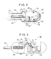
- FIG. 2 A particular example of embodiment of an apparatus 6 implemented in the first phase of the process is given by the apparatus 200 shown in the Figure 2.
- the propulsion means consisting of orifices 202, here three in number, arranged symmetrically.
- orifices 204 are arranged on the lateral surface 203. allowing lateral movement of the device 200 and the orifices 205 allowing the rotation of the apparatus 200.
- jets of 206 pressurized fluid are emitted to produce a thrust that displaces the apparatus 200.
- the pressurized fluid is brought in from the outside by a tube 207 connected to the rear of the device 200.
- the device 200 of general cylindrical shape further comprises at the front a compartment 208 protected by a rounded visor 209 in which is housed a gripping device view camera such as a video camera 210.
- the visor 209 can be equipped with a system cleaning such as water jets and / or a wiper not shown.
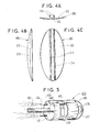
- a particular example of embodiment of an apparatus 10 implemented in the second phase of the process is given by the apparatus 300 shown in FIG. 3.
- the apparatus 300 prepares the locations where will be fixed the maintenance elements as they were determined following the topographic survey carried out during the first phase. These locations are identified for example by a shooting device directed towards the internal wall 7, such as a camera 301 placed in the device 300 and protected by a window 302.
- the device 300 also includes a rotary device 303 carrying an abrasive tool using for example sand, sandpaper or a wire brush.
- the chosen location is then dusted and dried by pressurized air expelled from at least one orifice 304.
- the apparatus also includes a reserve 305 of holding elements 306 communicating with a setting tool 307 through a passage 308 the along which the elements 306 are conveyed to the tool 307.
- the fixing means consists of glue 309 contained in a pressure tank 310 connected by at least one pipe 311 at the upper part of the tool 307.
- the tool 307 is for example a pneumatic or hydraulic press.
- the apparatus 300 moves by propulsion under the effect of a pressurized fluid, in this case preferably a gas like air, arriving by the tube 312 in communication with the outside and connected to orifices not shown located at the rear of the apparatus 300.
- the pressurized air arriving through the tube 312 can also be used to supply the orifice 304.
- the apparatus 300 is propelled by pressurized air sent via the pipe 312 to the location chosen to fix a holding element 306 identified by the camera 301.
- the admission of pressurized air is interrupted and the device 303 activates the tool which it carries.
- the abrasion can be carried out dry, and in this case a jet of pulsed air through the orifice 304 makes it possible to dust the site, or in the presence of water, and in this case the pulsed air preferably hot is used to dry the chosen location.
- a holding element 306 is then sent from the reserve 305 to the setting tool 307.
- glue 309 is then deposited on the surface of the element 306 which faces the internal wall 7.
- the holding element 306 is finally applied to the internal wall 7 by means of the tool 307.
- the adhesive is deposited on the chosen location of the wall 7 and a holding element 306 is applied to the adhesive deposit 309 using the tool 307.
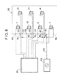
- FIG. 4A is a side view of the holding element 306 along a longitudinal axis of the cavity corresponding to the direction of movement of the device.
- the holding member 306 includes a base 312 of curved shape matching the profile of the wall on which it will be fixed and an elongated retainer 313 the cross section of which is in the form of a ring interrupted delimiting a housing 314 in which the element will be inserted tubular.
- FIG. 4B is a side view of the holding element 306 according to a transverse axis of the cavity allowing to observe its hydrodynamic shape in the direction of movement of the device.
- Figure 4C is a bottom view of the holding element 306 showing the base 312 of generally oval shape and the retaining member 313 leaving the housing 314 accessible for the introduction of the tubular element.
- FIG. 5 A particular embodiment of an apparatus 13 implemented in the third phase of the process is given by the apparatus 400 shown in the Figure 5.
- the means of propulsion consisting of jets of pressurized fluid 402 expelled orifices 403, here three in number, arranged symmetrically connected to a tube 404 for supplying a pressurized fluid from the outside.
- Device 400 is fitted with a 405 shooting device located inside a compartment 406 located at the front of the device and protected by a rounded visor 407.
- a gutter 408 is provided on the device 400 so that it can receive and guide the tubular element 8.
- the apparatus 400 is also equipped with a medium 409, placed inside the device, allowing the element to be applied tubular 8 against the internal wall 7 on which the holding elements 306. Arrived at the height of a holding element 306, the apparatus 400 stops its progression and the tubular element 8 elongated in the gutter 408 is pushed vertically upwards by means 409, which is for example a press, through an opening 410 made in the bottom of the gutter 408.
- the press 409 is preferably controlled by a means hydraulic or pneumatic.
- the device 400 can be equipped with a water level not shown to locate the vertical.
- FIG. 6 shows an apparatus 600 which is a variant of the apparatus 200 of FIG. 2.
- orifices secondary 602 can be arranged as shown in Figure 6.
- the method according to the invention is advantageously implemented thanks to an apparatus comprising a control means 700 directed from the outside whose operation is shown diagrammatically in FIGS. 7 and 8.
- the means of control 700 of the propulsion means and of the orientation means of the apparatus remote-controlled according to the invention is shown in section in Figure 7.
- valve 701 one end of which 702 is connected to an inlet of fluid 703 under high pressure and the other end of which 704 directs the jet of fluid under pressure to an orifice of the propulsion means or of the orientation means of the device.
- the valve 701 is actuated by the pressure of a fluid arriving by a control tube 705 serving as a switch.
- the 701 valve can include means allowing it to modulate the power of the fluid jet at the exit from end 704.
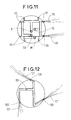
- a control means 800 comprising several valves similar to that of FIG. 2, each communicating with a or several orifices corresponding to a possible displacement.
- a P valve controls the means of propulsion
- RD and RG valves control respectively the rotation of the device to the right and to the left
- of the TD and TG valves control a horizontal movement allowing the device to turn towards the right or left
- valves D and M control movement vertical allowing the device to descend or ascend.
- Each of these valves is connected respectively to the fluid inlet 801 under high pressure.
- the inputs 801 communicate with a common tube 802 which brings the fluid put under high pressure by an 803 compressor placed outside.
- Each of these valves is actuated by a fluid under less pressure driven by a tubing 804.
- the switch constituted by the supply of pressurized fluid is controlled from the outside by the operator through a pressure switch 805 which imposes the corresponding pressure setpoint when each valve opens or closes.
- Control means, propulsion means and means of orientation of the apparatus used in the method according to the invention uses as a source of energy a pressurized fluid.
- the fluid supply intended for ensure the propulsion takes place at a high pressure so that it is possible to release a power of up to several kW when the fluid is reduced to atmospheric pressure.
- the fluid pressure in the tubing of valve control is less.
- the pressurized fluid intended to ensure the propulsion and orientation is distributed in the device according to the invention by several entrances.
- Figure 9 shows in section a possible arrangement of these inputs in a cylindrical compartment 900 of the apparatus.
- 901 entries of a diameter for example of the order of 12mm, arranged on a circle 902 centered on the longitudinal axis 903 of the apparatus, have the role of supplying fluid under pressure, via a valve, respectively the propulsion ports or the ports orientation.
- Tubes 904 of smaller diameter, of the order of 1mm to 2mm and arranged on a circle 905 centered on the axis 903, allow the admission of the pressurized fluid actuating the valves of the control means.
- FIGS. 10A and 10B Each of the 904 tubing is in the extension of a tubing 907 coming from the outside.
- Tubing 907 can be arranged around tube 906, of larger diameter, to form a first variant 10A of the conductor 207 of FIG. 2.
- the pipes 907 can also be placed inside the tube 906 to form a second variant 10B of the conductor 207 of FIG. 2.
- the tube 906 and the pipes 907 are preferably made of a flexible material capable of hugging curves resulting from moving the device.
- FIG. 11 is a section showing an example of arrangement of the holes to move the device used vertically and horizontally in the process according to the invention.
- Each pair of orifices producing a jet of fluid in the same direction is connected to a valve corresponding to a displacement possible.
- the valve TG is open and a jet of horizontal fluid 110 escapes from each of the corresponding orifices 111. Under the effect of these jets, the device turns to the left in a horizontal plane.
- the RG valve communicates with three orifices 120 arranged symmetrically and oriented at the same angle, inclusive between 0 ° and 45 °, relative to the circumference of the device.
- the RG valve is open and a fluid jet 121 escapes in a vertical plane of each of the orifices 120 corresponding to it. Under the effect of these jets, the device rotates clockwise in a vertical plane.
Abstract
Description
Une première phase consiste à rendre la paroi interne de la cavité apte à recevoir l'élément tubulaire. Cette phase est principalement une phase d'exploration et de nettoyage des parois de la cavité. L'exploration peut être réalisée à l'aide d'une caméra reliée à un système de traitement et d'exploitation des données, comme décrit dans le document FR-2 609 417. Il est connu d'effectuer le nettoyage d'une cavité à l'aide d'un fluide sous pression, notamment un liquide détergent, projeté par un appareil qui se déplace dans la cavité. Les jets de fluide sous pression peuvent être simultanément utilisés pour la propulsion et la stabilisation de l'appareil comme le décrit le document FR-2 609 417. Si la paroi interne de la cavité est dégradée, il peut être nécessaire de combler certaines dépressions à l'aide d'un mastic comme le décrit le document US-4,782,786.
Une deuxième phase a pour but de mettre en place un moyen destiné à maintenir l'élément tubulaire dans la position qui lui a été assignée. Il s'agit la plupart du temps d'un système comprenant des éléments de maintien répartis régulièrement sur la paroi de la cavité. Le document DE-197 01 787 décrit un système qui est composé d'éléments servant à recevoir le câble et d'un moyen de fixation de ces éléments constitué d'une bague fermée en acier spécial qui est précontrainte élastiquement et s'applique contre la paroi du tube. Le document DE-198 26 880 décrit un dispositif de retenue d'un câble utilisant un élément en plastique à mémoire de forme qui adopte la forme souhaitée sous l'effet du chauffage ou de l'humidité afin de plaquer le câble contre la paroi interne de la cavité. Cette technique est coûteuse et ne se justifie que dans le cas de parois très dégradées.
Une troisième phase est l'installation proprement dite d'un élément tubulaire dans la cavité. L'élément tubulaire est entraíné dans la cavité par un moyen mobile, puis mis en place et retenu dans le système de maintien préalablement fixé.
- une première phase comprenant ladite étape de nettoyage de la paroi interne de ladite cavité, et comprenant en outre une étape de relevé topographique de la paroi interne de ladite cavité,
- une deuxième phase comprenant une étape de détermination de la position des moyens de maintien dudit élément tubulaire sur ladite paroi interne, et une étape de pose desdits moyens de maintien sur ladite paroi interne, lesdits moyens de maintien comprenant des éléments de maintien dudit élément tubulaire et des moyens de fixation desdits éléments de maintien sur ladite paroi,
- une troisième phase de guidage et de mise en place dudit élément tubulaire dans lesdits moyens de maintien comprenant ladite étape de mise en contact dudit élément tubulaire avec lesdits éléments de maintien et ladite étape de fixation dudit élément tubulaire par pressage contre ladite paroi interne.
- on examine la paroi de ladite cavité afin d'en relever la topographie,
- on détermine les opérations de nettoyage nécessaires pour rendre la paroi interne de ladite cavité apte à recevoir lesdits moyens de maintien,
- on nettoie ladite paroi interne par action d'un jet de fluide sous pression,
- si nécessaire, on actionne un outil exerçant une action physique sur
ladite paroi.
Le relevé topographique de la paroi interne de la cavité peut être effectué par un moyen d'exploration et de guidage placé sur un appareil mobile se déplaçant dans la cavité. En mode exploration, il peut par exemple transmettre des données reflétant la topologie de la paroi de la portion de cavité située à l'avant de l'appareil au cours de son déplacement à un moyen d'enregistrement de ces données, comme un ordinateur. En mode guidage, les données sont visualisées par exemple sur un écran et l'opérateur peut ainsi de l'extérieur guider l'appareil de manière précise et adapter son déplacement aux obstacles rencontrés. Le moyen d'exploration et guidage peut être commandé électriquement, mais de préférence la commande est hydraulique ou pneumatique. De préférence le moyen d'exploration et guidage est un dispositif de prise de vue tel qu'une caméra vidéo. Un moyen d'éclairage peut en outre être associé au moyen d'exploration et guidage. De façon classique le moyen d'éclairage peut être constitué par une ampoule alimentée électriquement. Mais, afin d'augmenter la sécurité des opérations en éliminant la présence de courant électrique, on choisit de préférence d'amener la lumière à l'aide d'au moins une fibre optique alimentée par une source lumineuse placée à l'extérieur. Un système de traitement et exploitation des données peut aussi être associé au moyen d'exploration et guidage.
L'étape de nettoyage est réalisée à l'aide d'un jet de fluide sous pression qui peut être également utilisé pour la propulsion du moyen de nettoyage. Pour un nettoyage efficace, on peut y associer l'action d'un outil capable d'exercer une action physique sur la paroi, comme un racloir, une brosse métallique, un dispositif d'abrasion (papier de verre) pour éliminer des surépaisseurs gênantes ou tout autre instrument apte à égaliser et assainir la surface interne de la paroi de la canalisation. La mise en oeuvre d'un tel outil peut se faire simultanément à l'action des jet de fluide sous pression ou bien lors d'un passage ultérieur.
- on détermine l'emplacement de chacun desdits moyens de maintien à partir dudit relevé topographique de la paroi interne,
- on prépare lesdits emplacements à recevoir lesdits moyens de maintien,
- on fixe lesdits éléments de maintien sur lesdits emplacements à l'aide
desdits moyens de fixation.
On détermine l'emplacement de chacun desdits moyens de maintien à l'aide d'un ordinateur à partir des données recueillies au cours de la première phase par le moyen d'exploration et guidage. Les emplacements déterminés sont alors soigneusement décapés et séchés afin de ne pas compromettre la fixation des éléments de maintien. La préparation de la paroi interne aux emplacements déterminés peut aussi comprendre des opérations destinées à faciliter l'accrochage des moyens de fixation, par exemple en augmentant la rugosité de la surface par un rainurage.
Selon une première variante, la deuxième phase comprend les étapes suivantes :
- on détermine l'emplacement de chacun desdits moyens de maintien à partir dudit relevé topographique,
- on prépare lesdits emplacements à recevoir lesdits moyens de maintien,
- on dépose lesdits moyens de fixation sur lesdits emplacements,
- on dispose lesdits éléments de maintien sur lesdits moyens de fixation de
manière à fixer lesdits éléments sur la paroi interne de ladite cavité.
Selon une seconde variante, la deuxième phase comprend les étapes suivantes :
- on détermine l'emplacement de chacun desdits moyens de maintien à partir dudit relevé topographique,
- on prépare lesdits emplacements à recevoir lesdits moyens de maintien,
- on dépose lesdits moyens de fixation sur lesdits éléments de maintien,
- on dispose lesdits éléments de maintien sur lesdits emplacements de
manière à ce que lesdits moyens de fixation soient placés entre lesdits éléments et
ladite paroi interne de ladite cavité.
Lesdits éléments de maintien sont des pièces comprenant un logement destiné à coopérer avec l'élément tubulaire. De préférence les éléments de maintien sont constitués par des pièces dont la forme est adaptée à la géométrie de la cavité. En particulier, dans les canalisations remplissant en outre d'autres fonctions qui nécessitent un nettoyage périodique, la forme des éléments de maintien sera définie de manière à résister aux moyens de nettoyage habituellement utilisés. De préférence lesdits éléments de maintien sont constitués d'un matériau apte à résister aux agressions de l'environnement, notamment aux agressions chimiques, comme une matière plastique telles que le PVC. De préférence les moyens de fixation sont constitués par une colle, qui peut être un solvant du PVC.
- on amène ledit élément tubulaire jusqu'au niveau de l'un desdits éléments de maintien par un moyen de guidage,
- on pousse ledit élément tubulaire à l'aide d'une presse vers ledit élément
de maintien jusqu'à ce que ledit élément tubulaire soit retenu par ledit élément de
maintien.
De préférence le moyen de guidage comporte en outre un moyen pour repérer la verticale, par exemple un niveau d'eau. De préférence encore ledit moyen de guidage comprend une gouttière dans laquelle est allongé l'élément tubulaire. De préférence ladite presse est une presse à commande hydraulique ou pneumatique.
Le déplacement de l'appareil selon l'invention dans la cavité doit être commandé à distance. Un autre avantage est l'absence d'énergie électrique pour commander le moyen de propulsion et le moyen d'orientation. D'une part ceci facilite la miniaturisation de l'appareil qui peut ainsi accéder à des zones tubulaires dont le diamètre est inférieur à 200mm. D'autre part la sécurité d'utilisation de cet appareil est améliorée par l'absence de courant électrique dans une zone difficilement contrôlable.
Selon un quatrième mode de réalisation de l'invention, dans l'étape du procédé destiné au nettoyage des parois souillées d'une canalisation en vue de l'installation d'un élément tubulaire comme un tuyau destiné à loger un ou plusieurs câbles, l'appareil comporte en outre un moyen de nettoyage. Ce moyen de nettoyage peut être constitué par un jet de fluide sous pression. Ce jet de fluide sous pression peut par exemple être également utilisé pour la propulsion. Ce moyen de nettoyage peut aussi comprendre un outil capable d'exercer une action physique sur la paroi, comme un racloir, une brosse métallique, un dispositif d'abrasion en vue d'éliminer des surépaisseurs gênantes ou tout autre instrument apte à égaliser et assainir la surface interne de la paroi de la canalisation.
- la figure 1 représente en coupe partielle une zone tubulaire à équiper et symbolise schématiquement les trois phases de l'installation,
- la figure 2 est une vue en perspective d'un exemple d'appareil utilisé pour la réalisation de la première phase,
- la figure 3 est une coupe d'un exemple d'appareil utilisé pour la réalisation de la deuxième phase,
- les figures 4A, 4B et 4C représentent respectivement vue de profil et de dessous un mode de réalisation d'un élément de maintien,
- la figure 5 est une vue en perspective d'un exemple d'appareil utilisé pour la réalisation de la troisième phase,
- la figure 6 montre une vue en perspective d'une variante de réalisation de l'appareil de la figure 2 comportant des orifices secondaires de propulsion,
- la figure 7 est une coupe montrant un mode de réalisation du moyen de commande de l'appareil utilisé pour la mise en oeuvre du procédé selon l'invention,
- la figure 8 est un schéma fonctionnel du moyen de commande de la figure 7,
- la figure 9 est une coupe transversale schématique montrant la disposition des entrées de fluide sous pression du moyen de commande de la figure 7,
- la figure 10A et 108 montrent en coupe deux dispositions des amenées de fluide sous pression,
- la figure 11 est une représentation schématique de la disposition des orifices du moyen d'orientation de l'appareil utilisé pour la mise en oeuvre du procédé selon l'invention lorsque ceux-ci sont destinés à produire un déplacement latéral de l'appareil,
- la figure 12 est une représentation schématique de la disposition des orifices du moyen d'orientation de l'appareil utilisé pour la mise en oeuvre du procédé selon l'invention lorsque ceux-ci sont destinés à produire une rotation de l'appareil.
L'élément tubulaire peut être notamment, mais pas exclusivement, un tuyau destiné à contenir des câbles à fibres optiques. Les appareils 6, 10 et 13 peuvent être propulsés par exemple par un fluide mis sous pression dans un compresseur 16 et acheminé par un tuyau 17 jusqu'à l'appareil correspondant.
Une fois introduit dans le conduit 4, l'appareil 300 est propulsé par de l'air sous pression envoyé via le tuyau 312 jusqu'à l'emplacement choisi pour y fixer un élément de maintien 306 repéré par la caméra 301. L'admission d'air sous pression est interrompue et le dispositif 303 met en action l'outil qu'il porte. L'abrasion peut être effectuée à sec, et dans ce cas un jet d'air pulsé au travers de l'orifice 304 permet de dépoussiérer l'emplacement, ou en présence d'eau, et dans ce cas l'air pulsé de préférence chaud est utilisé pour sécher l'emplacement choisi. Un élément de maintien 306 est alors envoyé depuis la réserve 305 vers l'outil de pose 307. Selon un premier mode de réalisation illustré sur la figure 3, grâce au tuyau 311, de la colle 309 est alors déposée sur la surface de l'élément 306 qui fait face à la paroi interne 7. L'élément de maintien 306 est enfin appliqué sur la paroi interne 7 au moyen de l'outil 307.
Selon un autre mode de réalisation non représenté, la colle est déposée sur l'emplacement choisi de la paroi 7 et un éléments de maintien 306 est appliqué sur le dépôt de colle 309 à l'aide de l'outil 307.
Claims (34)
- Procédé d'installation d'un élément tubulaire dans une cavité inaccessible comprenant au moins les étapes suivantes : une étape de nettoyage de la paroi interne de ladite cavité, une étape de mise en contact dudit élément tubulaire avec des éléments de maintien et une étape de fixation dudit élément tubulaire par pressage contre la paroi de ladite cavité, caractérisé en ce qu'il comprend les trois phases successives suivantes :une première phase comprenant ladite étape de nettoyage de la paroi interne de ladite cavité, et comprenant en outre une étape de relevé topographique de la paroi interne de ladite cavité,une deuxième phase comprenant une étape de détermination de la position des moyens de maintien dudit élément tubulaire sur ladite paroi interne, et une étape de pose desdits moyens de maintien sur ladite paroi interne, lesdits moyens de maintien comprenant des éléments de maintien dudit élément tubulaire et des moyens de fixation desdits éléments de maintien sur ladite paroi,une troisième phase de guidage et de mise en place dudit élément tubulaire dans lesdits moyens de maintien comprenant ladite étape de mise en contact dudit élément tubulaire avec lesdits éléments de maintien et ladite étape de fixation dudit élément tubulaire par pressage contre ladite paroi interne.
- Procédé selon la revendication 1, dans lequel ladite première phase comprend les étapes suivantes :on examine la paroi interne de ladite cavité afin d'en relever la topographie,on détermine les opérations de nettoyage nécessaires pour rendre la paroi interne de ladite cavité apte à recevoir lesdits moyens de maintien,on nettoie ladite paroi interne par action d'un jet de fluide sous pression,si nécessaire, on actionne un outil exerçant une action physique sur ladite paroi.
- Procédé selon l'une des revendications 1 et 2, dans lequel ledit relevé est effectué par un moyen d'exploration et guidage.
- Procédé selon la revendication 3, dans lequel un moyen d'éclairage est associé audit moyen d'exploration et guidage.
- Procédé selon la revendication 4, dans lequel ledit moyen d'éclairage est une fibre optique.
- Procédé selon la revendication 3, dans lequel un système de traitement et exploitation des données est associé audit moyen d'exploration et guidage.
- Procédé selon l'une des revendications précédentes, dans lequel ladite deuxième phase comprend les étapes suivantes :on détermine l'emplacement de chacun desdits moyens de maintien à partir dudit relevé topographique de ladite paroi interne,on prépare lesdits emplacements à recevoir lesdits moyens de maintien,on fixe lesdits éléments de maintien sur lesdits emplacements à l'aide desdits moyens de fixation.
- Procédé selon la revendication 7, dans lequel ladite deuxième phase comprend les étapes suivantes :on détermine l'emplacement de chacun desdits moyens de maintien à partir dudit relevé topographique,on prépare lesdits emplacements à recevoir lesdits moyens de maintien,on dépose des moyens de fixation sur lesdits emplacements,on dispose des éléments de maintien sur lesdits moyens de fixation.
- Procédé selon la revendication 7, dans lequel ladite deuxième phase comprend les étapes suivantes :on détermine l'emplacement de chacun desdits moyens de maintien à partir dudit relevé topographique,on prépare lesdits emplacements à recevoir lesdits moyens de maintien,on dépose des moyens de fixation sur des éléments de maintien,on dispose lesdits éléments de maintien sur lesdits emplacements de manière à ce que lesdits moyens de fixation soient placés entre lesdits éléments et ladite paroi interne de ladite cavité.
- Procédé selon l'une des revendications 7 à 9, dans lequel lesdits éléments de maintien sont des pièces comprenant un logement destiné à coopérer avec l'élément tubulaire.
- Procédé selon l'une des revendications 7 à 10, dans lequel lesdits moyens de fixation sont constitués par une colle.
- Procédé selon l'une des revendications précédentes, dans lequel ladite troisième phase comprend les étapes suivantes :on amène ledit élément tubulaire jusqu'au niveau de l'un desdits éléments de maintien par un moyen de guidage,on pousse ledit élément tubulaire à l'aide d'une presse vers ledit élément de maintien jusqu'à ce que ledit élément tubulaire soit retenu par ledit élément de maintien.
- Procédé selon la revendication 12, dans lequel ledit moyen de guidage comprend une gouttière
- Procédé selon l'une des revendications 12 et 13, dans lequel ledit moyen de guidage comprend un moyen pour repérer la verticale.
- Procédé selon l'une des revendications 12 à 14, dans lequel ladite presse est une presse à commande hydraulique ou pneumatique.
- Procédé selon l'une des revendications précédentes, utilisant un appareil comportant un moyen de déplacement linéaire par propulsion et un moyen permettant son orientation dans l'espace, ledit moyen de propulsion et ledit moyen d'orientation étant commandé par un moyen de commande hydraulique ou pneumatique.
- Procédé selon la revendication 16, dans lequel ledit moyen de commande comprend un interrupteur hydraulique ou pneumatique, une valve et une entrée de fluide sous pression coopérant avec ladite valve.
- Procédé selon l'une des revendications 16 et 17, dans lequel ledit moyen d'orientation comprend au moins un orifice placé sur la surface latérale externe dudit appareil et communiquant avec ladite valve.
- Procédé selon l'une des revendications 16 à 18, dans lequel ledit moyen de propulsion comprend au moins un orifice principal disposé sur la surface externe dudit appareil et communiquant avec ladite valve.
- Procédé selon la revendication 19, dans lequel ledit moyen de propulsion comprend en outre au moins un orifice secondaire disposé sur un tube d'amenée de fluide sous pression raccordé à ladite entrée de fluide.
- Procédé selon l'une des revendications 16 à 20, dans lequel ledit appareil comporte en outre un moyen d'exploration et guidage.
- Procédé selon la revendication 21, dans lequel ledit moyen d'exploration et de guidage est commandé hydrauliquement.
- Procédé selon la revendication 21, dans lequel ledit moyen d'exploration et de guidage est commandé pneumatiquement.
- Procédé selon l'une des revendications 21 à 23, dans lequel ledit moyen d'exploration et de guidage est un dispositif de prise de vue.
- Procédé selon l'une des revendications 16 à 24, dans lequel ledit appareil comporte en outre un moyen d'éclairage.
- Procédé selon la revendication 25, dans lequel ledit moyen d'éclairage comprend au moins une fibre optique alimentée par une source lumineuse placée à l'extérieur.
- Procédé selon l'une des revendications 16 à 26, dans lequel ledit appareil comporte en outre un moyen pour repérer la verticale.
- Procédé selon l'une des revendications 16 à 27, dans lequel ledit appareil comporte en outre un moyen de nettoyage.
- Procédé selon la revendication 28, dans lequel ledit moyen de nettoyage est constitué par un jet de fluide sous pression
- Procédé selon la revendication 29, dans lequel ledit jet de fluide sous pression est également utilisé pour la propulsion.
- Procédé selon la revendication 28, dans lequel ledit moyen de nettoyage comprend un outil capable d'exercer une action physique sur la paroi.
- Procédé selon l'une des revendications 16 à 31, dans lequel ledit appareil comporte en outre un moyen de guidage d'un élément tubulaire.
- Procédé selon l'une des revendications 16 à 32, dans lequel ledit appareil comporte en outre un moyen d'application d'un élément tubulaire sur une paroi.
- Procédé selon l'une des revendications précédentes, pour l'installation d'un élément tubulaire dans une cavité inaccessible de diamètre inférieur à 200mm et d'au moins 80mm.
Applications Claiming Priority (4)
| Application Number | Priority Date | Filing Date | Title |
|---|---|---|---|
| FR0111667 | 2001-09-10 | ||
| FR0111667A FR2829553B1 (fr) | 2001-09-10 | 2001-09-10 | Procede d'installation d'un cable dans une cavite inaccessible a un operateur |
| FR0111666 | 2001-09-10 | ||
| FR0111666A FR2829556A1 (fr) | 2001-09-10 | 2001-09-10 | Appareil deplacable dans une cavite inaccessible |
Publications (2)
| Publication Number | Publication Date |
|---|---|
| EP1291991A2 true EP1291991A2 (fr) | 2003-03-12 |
| EP1291991A3 EP1291991A3 (fr) | 2005-09-28 |
Family
ID=26213180
Family Applications (1)
| Application Number | Title | Priority Date | Filing Date |
|---|---|---|---|
| EP02292133A Withdrawn EP1291991A3 (fr) | 2001-09-10 | 2002-08-29 | Procédé d'installation d'un élément tubulaire dans une cavité inaccessible à un opérateur |
Country Status (2)
| Country | Link |
|---|---|
| US (1) | US20030047276A1 (fr) |
| EP (1) | EP1291991A3 (fr) |
Cited By (2)
| Publication number | Priority date | Publication date | Assignee | Title |
|---|---|---|---|---|
| NL2003783C2 (nl) * | 2009-11-10 | 2011-05-11 | J G Spijker Holding B V | Werkwijze en een systeem voor het aansluiten van een gebouw op een leidingnetwerk |
| ITRM20120051A1 (it) * | 2012-02-14 | 2013-08-15 | Aniello Oliviero | Sonda passafili a reazione pneumatica. |
Families Citing this family (5)
| Publication number | Priority date | Publication date | Assignee | Title |
|---|---|---|---|---|
| DE102009059717A1 (de) * | 2009-11-30 | 2011-06-30 | Rosen Swiss Ag | Molch |
| DE102013009708B4 (de) * | 2013-06-10 | 2018-01-11 | Jt-Elektronik Gmbh | Spülkopf für Abwasserkanäle und Zuführung von Medien |
| DE102013009967B4 (de) * | 2013-06-13 | 2018-01-11 | Jt-Elektronik Gmbh | Mehrfach-Spüldüse für Abwasserkanäle |
| DE102016123038A1 (de) * | 2016-11-29 | 2018-05-30 | Ritec Rohrinspektionstechnik Gmbh | Vorrichtung zur Inspektion und Reinigung eines Leitungs- oder Rohrabschnitts |
| US20210213478A1 (en) * | 2020-01-13 | 2021-07-15 | Paul DEL PIERO | Jetter nozzle assembly with reduced thread exposure |
Citations (1)
| Publication number | Priority date | Publication date | Assignee | Title |
|---|---|---|---|---|
| DE19752424A1 (de) * | 1997-11-26 | 1999-05-27 | Siemens Ag | Verfahren zum Verlegen von Lichtwellenleiterkabeln in Rohrleitungen bestehender Versorgungsleitungssysteme |
Family Cites Families (9)
| Publication number | Priority date | Publication date | Assignee | Title |
|---|---|---|---|---|
| GB2129627B (en) * | 1982-09-22 | 1986-12-10 | Water Res Centre | Installation of communications cables |
| AU574136B2 (en) * | 1985-02-13 | 1988-06-30 | Ka-Te System Ag | Device to fill in and glue all kinds of depressions in inaccessible pipe conduits |
| FR2688292B1 (fr) * | 1992-03-06 | 1995-07-13 | Frey Andre | Dispositif de reparation in situ de conduits ou de canalisations non visitables et procede de rehabilitation mettant en óoeuvre ledit dispositif. |
| US5509988A (en) * | 1994-06-02 | 1996-04-23 | Northrop Grumman Corporation | Method of affixing material on a substrate to the inner surface of a tube |
| EP0936713A1 (fr) * | 1998-02-17 | 1999-08-18 | KA-TE System AG | Dispositif d'insertion d'objets allongés dans des pinces |
| EP0936479A1 (fr) * | 1998-02-17 | 1999-08-18 | KA-TE System AG | Chemisage avec un organe de verrouillage |
| US6712556B2 (en) * | 2001-05-18 | 2004-03-30 | G. Gregory Penza | Method and apparatus for routing cable in existing pipelines |
| US6644892B2 (en) * | 2001-06-08 | 2003-11-11 | Nihonhume Corporation | Method for attaching cable and cable holder |
| FR2830069B1 (fr) * | 2001-09-27 | 2005-06-24 | Cit Alcatel | Dispositif de fixation d'un element tubulaire dans une cavite inaccessible |
-
2002
- 2002-08-29 EP EP02292133A patent/EP1291991A3/fr not_active Withdrawn
- 2002-09-09 US US10/236,912 patent/US20030047276A1/en not_active Abandoned
Patent Citations (1)
| Publication number | Priority date | Publication date | Assignee | Title |
|---|---|---|---|---|
| DE19752424A1 (de) * | 1997-11-26 | 1999-05-27 | Siemens Ag | Verfahren zum Verlegen von Lichtwellenleiterkabeln in Rohrleitungen bestehender Versorgungsleitungssysteme |
Cited By (2)
| Publication number | Priority date | Publication date | Assignee | Title |
|---|---|---|---|---|
| NL2003783C2 (nl) * | 2009-11-10 | 2011-05-11 | J G Spijker Holding B V | Werkwijze en een systeem voor het aansluiten van een gebouw op een leidingnetwerk |
| ITRM20120051A1 (it) * | 2012-02-14 | 2013-08-15 | Aniello Oliviero | Sonda passafili a reazione pneumatica. |
Also Published As
| Publication number | Publication date |
|---|---|
| US20030047276A1 (en) | 2003-03-13 |
| EP1291991A3 (fr) | 2005-09-28 |
Similar Documents
| Publication | Publication Date | Title |
|---|---|---|
| EP0132423B1 (fr) | Méthode et dispositif de mesure et d'intervention dans un puits | |
| EP1868020B1 (fr) | Procédé et dispositif d'installation de cables et gaines dans une canalisation non visitable | |
| FR2770986A1 (fr) | Prise pour le raccordement d'un tuyau d'aspiration de poussieres a une installation d'aspiration centralisee | |
| EP0006812B1 (fr) | Procédé pour la pose de conduites immergées et dispositif s'y rapportant | |
| CA1136390A (fr) | Porte-outil mobile pour travail sur une plaque tubulaire | |
| EP1291991A2 (fr) | Procédé d'installation d'un élément tubulaire dans une cavité inaccessible à un opérateur | |
| EP2577158B1 (fr) | Dispositif de guidage pour lance flexible | |
| EP0520847B1 (fr) | Procédé de travail au laser dans une zone contaminée d'une installation nucléaire, et équipement pour sa mise en oeuvre | |
| CA1057539A (fr) | Methode de soudure de conduites immergees par aboutement de manchon et dispositif de mise en oeuvre | |
| EP2678865B1 (fr) | Dispositif d'inspection d'un générateur de vapeur | |
| EP0897455B1 (fr) | Socle de support de manifold pour installation d'exploitation petroliere et procede de pose de l'installation | |
| EP2998963A1 (fr) | Dispositif de guidage pour lance flexible | |
| FR2557055A1 (fr) | Appareil de transport et de positionnement dans un conduit | |
| CA1057538A (fr) | Methode de soudure de conduites immergees par manchon telescopique et dispositif de mise en oeuvre | |
| FR2667519A1 (fr) | Dispositif pour vehiculer a l'interieur de conduit ou analogue un ensemble de travail. | |
| EP0477349A1 (fr) | Dispositif pour l'abandon et la recuperation d'une charge lourde sur fond marin. | |
| FR2470699A1 (fr) | Dispositif commandable a distance d'intervention sur des structures immergees, notamment de raccordement de canalisations sous-marines | |
| FR2701278A1 (fr) | Procédé de curage et dispositif de curage et d'inspection de collecteurs d'égouts. | |
| FR2829553A1 (fr) | Procede d'installation d'un cable dans une cavite inaccessible a un operateur | |
| FR2829556A1 (fr) | Appareil deplacable dans une cavite inaccessible | |
| EP0475815B1 (fr) | Procédé pour la pose en conduite de grande longueur d'un câble de télécommunication, et dispositif pour la mise en oeuvre de ce procédé | |
| EP1147825B1 (fr) | Dispositif de contrôle vidéo et de curage de canalisations par jet | |
| EP0302783B1 (fr) | Procédé de réalisation d'une installation de transport d'électricité ou analogue entre un local technique et des emplacements disséminés sur un plateau, et installation ainsi réalisée | |
| CA1058892A (fr) | Raccordement de deux conduites immergees par aboutement et soudure d'un manchon | |
| FR2663676A1 (fr) | Methode et dispositif perfectionnes pour conduire des operations de mesure ou des interventions dans un puits. |
Legal Events
| Date | Code | Title | Description |
|---|---|---|---|
| PUAI | Public reference made under article 153(3) epc to a published international application that has entered the european phase |
Free format text: ORIGINAL CODE: 0009012 |
|
| AK | Designated contracting states |
Kind code of ref document: A2 Designated state(s): AT BE BG CH CY CZ DE DK EE ES FI FR GB GR IE IT LI LU MC NL PT SE SK TR Designated state(s): AT BE BG CH CY CZ DE DK EE ES FI FR GB GR IE IT LI LU MC NL PT SE SK TR |
|
| AX | Request for extension of the european patent |
Extension state: AL LT LV MK RO SI |
|
| PUAL | Search report despatched |
Free format text: ORIGINAL CODE: 0009013 |
|
| AK | Designated contracting states |
Kind code of ref document: A3 Designated state(s): AT BE BG CH CY CZ DE DK EE ES FI FR GB GR IE IT LI LU MC NL PT SE SK TR |
|
| AX | Request for extension of the european patent |
Extension state: AL LT LV MK RO SI |
|
| AKX | Designation fees paid | ||
| REG | Reference to a national code |
Ref country code: DE Ref legal event code: 8566 |
|
| STAA | Information on the status of an ep patent application or granted ep patent |
Free format text: STATUS: THE APPLICATION IS DEEMED TO BE WITHDRAWN |
|
| 18D | Application deemed to be withdrawn |
Effective date: 20050901 |