EP1291948A1 - Fuel cell power generation system, and fuel cell power generation interrupting method - Google Patents
Fuel cell power generation system, and fuel cell power generation interrupting method Download PDFInfo
- Publication number
- EP1291948A1 EP1291948A1 EP01938610A EP01938610A EP1291948A1 EP 1291948 A1 EP1291948 A1 EP 1291948A1 EP 01938610 A EP01938610 A EP 01938610A EP 01938610 A EP01938610 A EP 01938610A EP 1291948 A1 EP1291948 A1 EP 1291948A1
- Authority
- EP
- European Patent Office
- Prior art keywords
- fuel cell
- reformer
- electric power
- hydrogen
- air
- Prior art date
- Legal status (The legal status is an assumption and is not a legal conclusion. Google has not performed a legal analysis and makes no representation as to the accuracy of the status listed.)
- Withdrawn
Links
Images


Classifications
-
- H—ELECTRICITY
- H01—ELECTRIC ELEMENTS
- H01M—PROCESSES OR MEANS, e.g. BATTERIES, FOR THE DIRECT CONVERSION OF CHEMICAL ENERGY INTO ELECTRICAL ENERGY
- H01M8/00—Fuel cells; Manufacture thereof
- H01M8/04—Auxiliary arrangements, e.g. for control of pressure or for circulation of fluids
- H01M8/04223—Auxiliary arrangements, e.g. for control of pressure or for circulation of fluids during start-up or shut-down; Depolarisation or activation, e.g. purging; Means for short-circuiting defective fuel cells
- H01M8/04231—Purging of the reactants
-
- H—ELECTRICITY
- H01—ELECTRIC ELEMENTS
- H01M—PROCESSES OR MEANS, e.g. BATTERIES, FOR THE DIRECT CONVERSION OF CHEMICAL ENERGY INTO ELECTRICAL ENERGY
- H01M8/00—Fuel cells; Manufacture thereof
- H01M8/04—Auxiliary arrangements, e.g. for control of pressure or for circulation of fluids
-
- H—ELECTRICITY
- H01—ELECTRIC ELEMENTS
- H01M—PROCESSES OR MEANS, e.g. BATTERIES, FOR THE DIRECT CONVERSION OF CHEMICAL ENERGY INTO ELECTRICAL ENERGY
- H01M8/00—Fuel cells; Manufacture thereof
- H01M8/04—Auxiliary arrangements, e.g. for control of pressure or for circulation of fluids
- H01M8/04007—Auxiliary arrangements, e.g. for control of pressure or for circulation of fluids related to heat exchange
- H01M8/04014—Heat exchange using gaseous fluids; Heat exchange by combustion of reactants
- H01M8/04022—Heating by combustion
-
- H—ELECTRICITY
- H01—ELECTRIC ELEMENTS
- H01M—PROCESSES OR MEANS, e.g. BATTERIES, FOR THE DIRECT CONVERSION OF CHEMICAL ENERGY INTO ELECTRICAL ENERGY
- H01M8/00—Fuel cells; Manufacture thereof
- H01M8/04—Auxiliary arrangements, e.g. for control of pressure or for circulation of fluids
- H01M8/04223—Auxiliary arrangements, e.g. for control of pressure or for circulation of fluids during start-up or shut-down; Depolarisation or activation, e.g. purging; Means for short-circuiting defective fuel cells
- H01M8/04228—Auxiliary arrangements, e.g. for control of pressure or for circulation of fluids during start-up or shut-down; Depolarisation or activation, e.g. purging; Means for short-circuiting defective fuel cells during shut-down
-
- H—ELECTRICITY
- H01—ELECTRIC ELEMENTS
- H01M—PROCESSES OR MEANS, e.g. BATTERIES, FOR THE DIRECT CONVERSION OF CHEMICAL ENERGY INTO ELECTRICAL ENERGY
- H01M8/00—Fuel cells; Manufacture thereof
- H01M8/04—Auxiliary arrangements, e.g. for control of pressure or for circulation of fluids
- H01M8/04298—Processes for controlling fuel cells or fuel cell systems
- H01M8/043—Processes for controlling fuel cells or fuel cell systems applied during specific periods
- H01M8/04303—Processes for controlling fuel cells or fuel cell systems applied during specific periods applied during shut-down
-
- H—ELECTRICITY
- H01—ELECTRIC ELEMENTS
- H01M—PROCESSES OR MEANS, e.g. BATTERIES, FOR THE DIRECT CONVERSION OF CHEMICAL ENERGY INTO ELECTRICAL ENERGY
- H01M8/00—Fuel cells; Manufacture thereof
- H01M8/06—Combination of fuel cells with means for production of reactants or for treatment of residues
- H01M8/0606—Combination of fuel cells with means for production of reactants or for treatment of residues with means for production of gaseous reactants
- H01M8/0612—Combination of fuel cells with means for production of reactants or for treatment of residues with means for production of gaseous reactants from carbon-containing material
-
- H—ELECTRICITY
- H01—ELECTRIC ELEMENTS
- H01M—PROCESSES OR MEANS, e.g. BATTERIES, FOR THE DIRECT CONVERSION OF CHEMICAL ENERGY INTO ELECTRICAL ENERGY
- H01M8/00—Fuel cells; Manufacture thereof
- H01M8/06—Combination of fuel cells with means for production of reactants or for treatment of residues
- H01M8/0662—Treatment of gaseous reactants or gaseous residues, e.g. cleaning
- H01M8/0668—Removal of carbon monoxide or carbon dioxide
-
- H—ELECTRICITY
- H01—ELECTRIC ELEMENTS
- H01M—PROCESSES OR MEANS, e.g. BATTERIES, FOR THE DIRECT CONVERSION OF CHEMICAL ENERGY INTO ELECTRICAL ENERGY
- H01M8/00—Fuel cells; Manufacture thereof
- H01M8/06—Combination of fuel cells with means for production of reactants or for treatment of residues
- H01M8/0662—Treatment of gaseous reactants or gaseous residues, e.g. cleaning
- H01M8/0675—Removal of sulfur
-
- Y—GENERAL TAGGING OF NEW TECHNOLOGICAL DEVELOPMENTS; GENERAL TAGGING OF CROSS-SECTIONAL TECHNOLOGIES SPANNING OVER SEVERAL SECTIONS OF THE IPC; TECHNICAL SUBJECTS COVERED BY FORMER USPC CROSS-REFERENCE ART COLLECTIONS [XRACs] AND DIGESTS
- Y02—TECHNOLOGIES OR APPLICATIONS FOR MITIGATION OR ADAPTATION AGAINST CLIMATE CHANGE
- Y02E—REDUCTION OF GREENHOUSE GAS [GHG] EMISSIONS, RELATED TO ENERGY GENERATION, TRANSMISSION OR DISTRIBUTION
- Y02E60/00—Enabling technologies; Technologies with a potential or indirect contribution to GHG emissions mitigation
- Y02E60/30—Hydrogen technology
- Y02E60/50—Fuel cells
Definitions
- the present invention relates to fuel cell electric power generating systems.
- a conventional fuel cell electric power generating system is of the configuration shown in Fig. 4 as described in Japanese Patent Laid-Open Gazette No. HEI 3-257762. That is, such a system includes a reformer 1 of producing hydrogen-rich gas from a source gas, a burner 2a as heating means 2 of heating the reformer 1, nitrogen equipment 16 located upstream of and connected to the reformer 1 via a nitrogen supply pipe 14 and a shut-off valve 15, and a fuel cell 9 located downstream of and connected to the reformer 1 via a reformed gas supply pipe 17 for generating electric power by reacting oxygen contained in air with hydrogen produced, the downstream side of hydrogen electrode 9a of the fuel cell 9 being connected to the burner 2a via an exhaust hydrogen connecting pipe 12.
- a reformer 1 of producing hydrogen-rich gas from a source gas includes a burner 2a as heating means 2 of heating the reformer 1, nitrogen equipment 16 located upstream of and connected to the reformer 1 via a nitrogen supply pipe 14 and a shut-off valve 15, and a fuel cell 9 located downstream of and connected to
- shut-off valve 15 it has been a practice to open the shut-off valve 15 to supply nitrogen as an inert gas from the nitrogen equipment 16 to the path of reformer 1 ⁇ reformed gas supply pipe 17 ⁇ hydrogen electrode 9a of fuel cell 9 ⁇ exhaust hydrogen connecting pipe 12 via the nitrogen supply pipe 14 in stopping the electric power generating operation, thereby purging the hydrogen-rich gas completely and causing it to be burned by the burner 2a.
- the conventional fuel cell electric power generating system prevents explosion of hydrogen by the purging operation with nitrogen thereby to ensure safety.
- Such a conventional fuel cell electric power generating system needs to have nitrogen equipment 16, such as a nitrogen cylinder, for the purging operation with nitrogen.
- nitrogen equipment 16 such as a nitrogen cylinder
- the system requires a large space and an increased initial cost for equipment.
- an increased running cost because such a nitrogen cylinder needs to be periodically replaced or replenished.
- the 1st invention of the present invention is a fuel cell electric power generating system comprising a reformer producing hydrogen-rich gas by utilizing a source gas, source gas supplying means of supplying said source gas to said reformer, first air supplying means of supplying purging air to said reformer, and a fuel cell generating electric power by utilizing the hydrogen-rich gas produced at the reformer and air for electric power generation supplied from outside, wherein in stopping the operation of said fuel cell, the supply of said source gas to said reformer is stopped and the hydrogen-rich gas remaining within the fuel cell electric power generating system, steam, and said purging air are passed in this order.
- the 2nd invention of the present invention is the fuel cell electric power generating system according to the 1st invention, wherein when the supply of said source gas to said reformer is stopped, steam is supplied to said reformer or water is supplied to said reformer and heated to generate steam, and subsequently, after lapse of a predetermined time, said purging air is supplied to said reformer by said first air supplying means.
- the 3rd invention of the present invention is the fuel cell electric power generating system according to the 2nd invention, wherein said predetermined time means a time taken for steam to purge the hydrogen-rich gas present within the fuel cell electric power generating system substantially completely.
- the 4th invention of the present invention is the fuel cell electric power generating system according to the 2nd invention, wherein said predetermined time means a time sufficient to provide a predetermined amount of steam between said hydrogen-rich gas and said purging air so as to avoid a dangerous state resulting from contact between said hydrogen-rich gas present within the fuel cell electric power generating system and said purging air.
- the 5th invention of the present invention is the fuel cell electric power generating system according to any one of the 1st to 4th inventions, wherein said reformer comprises water supplying means of supplying water for producing hydrogen to said reformer and heating means of heating said reformer to turn said water for producing hydrogen into steam; and said reformer produces said hydrogen-rich gas by utilizing said steam also.
- the 6th invention of the present invention is the fuel cell electric power generating system according to the 5th invention, wherein steam is generated by heating said water for producing hydrogen even after the operation of the fuel cell is stopped.
- the 7th invention of the present invention is the fuel cell electric power generating system according to the 5th or 6th invention, wherein said heating means use hydrogen off-gas exhausted from said fuel cell as a fuel.
- the 8th invention of the present invention is the fuel cell electric power generating system according to the 7th invention, wherein after steam reaches said heating means, the supply of said water for producing hydrogen to said reformer is stopped, while said purging air is supplied to said reformer.
- the 9th invention of the present invention is the fuel cell electric power generating system according to any one of the 1st to 8th inventions, further comprising a carbon monoxide eliminator located downstream of said reformer for eliminating carbon monoxide contained in the hydrogen-rich gas produced at the reformer, and second air supplying means of supplying air for eliminating carbon monoxide to said carbon monoxide eliminator, wherein said fuel cell is supplied with hydrogen-rich gas from which carbon monoxide is already eliminated by said carbon monoxide eliminator.
- the 10th invention of the present invention is the fuel cell electric power generating system according to the 9th invention, wherein said first air supplying means functions also as said second air supplying means and switching means is provided of switching a receiver of the supply of air from said first air supplying means to said reformer or said carbon monoxide eliminator.
- the 11th invention of the present invention is a method of stopping fuel cell electric power generation, which is employed after electric power generation performed using a reformer producing hydrogen-rich gas by utilizing a source gas, source gas supplying means of supplying said source gas to said reformer, first air supplying means of supplying purging air to said reformer, and a fuel cell generating electric power by utilizing the hydrogen-rich gas produced at the reformer and air for electric power generation supplied from outside, the method comprising, in stopping the operation of said fuel cell, stopping the supply of said source gas to said reformer and passing the hydrogen-rich gas remaining within a fuel cell electric power generating system, steam, and said purging air in this order.
- the 12th invention of the present invention is the method of stopping fuel cell electric power generation according to the 11th invention, wherein when the supply of said source gas to said reformer is stopped, steam is supplied to said reformer or water is supplied to said reformer and heated to generate steam, and subsequently, after lapse of a predetermined time, said purging air is supplied to said reformer by said first air supplying means.
- the 13th invention of the present invention is the method of stopping fuel cell electric power generation according to the 12th invention, wherein said predetermined time means a time taken for steam to purge the hydrogen-rich gas present within the fuel cell electric power generating system substantially completely.
- the 14th invention of the present invention is the method of stopping fuel cell electric power generation according to the 12th invention, wherein said predetermined time means a time sufficient to provide a predetermined amount of steam between said hydrogen-rich gas and said purging air so as to avoid a dangerous state resulting from contact between said hydrogen-rich gas present within the fuel cell electric power generating system and said purging air.
- Fig. 1 is a diagram showing the system configuration of a fuel cell electric power generating system according to embodiment 1 of the present invention.
- Reference numeral 1 designates a reformer filled therein with a reforming catalyst 1a for causing a reforming reaction to occur.
- the reformer 1 is provided with a burner 2a as heating means 2, and an upstream 1b inlet of the reformer 1 is equipped with a source gas supplying valve 3, a water pump 4a as water supplying means 4, and an air pump 5a as air supplying means 5, the pumps 4a and 5a being connected to the upstream 1b inlet so as to join with the upstream 1b
- a desulfurizer 6 for removing a sulfur content contained in a source gas is provided between the upstream 1b of the reformer 1 and the source gas supplying valve 3.
- Reference numeral 3a designates source gas supplying means of supplying the source gas to the reformer 1.
- Reference numeral 7 designates a carbon monoxide eliminator connected to the downstream side of the reformer 1, the carbon monoxide eliminator 7 being filled therein with a catalyst 7a for causing a carbon monoxide eliminating reaction to occur. Between the reformer 1 and the carbon monoxide eliminator 7 may be provided a modifier 8 for lowering the carbon monoxide concentration to a certain degree by a modifying reaction.
- Reference numeral 9 designates a fuel cell connected to the downstream side of the carbon monoxide eliminator 7, the fuel cell 9 comprising a hydrogen electrode 9a and an oxygen electrode 9b, the oxygen electrode 9b being connected to a blower 10.
- Reference numeral 11 designates a control unit of controlling the operation of the system.
- the source gas supplying valve 3 is first opened to supply the source gas such as hydrocarbon to the reformer 1 from the upstream 1b of the reformer 1.
- water is supplied to the reformer 1 from the water supplying means 4.
- the source gas thus supplied is heated with the burner 2a when it passes through the reforming catalyst 1a, and water supplied to the reformer 1 is also heated with the burner 2a and turned into steam, so that a reforming reaction occurs between the source gas and steam to produce a hydrogen-rich gas.
- the reformer 1 in embodiment 1 produces the hydrogen-rich gas through the reforming reaction of the steam reforming system.
- the hydrogen-rich gas generally contains carbon monoxide and, hence, the supply of the hydrogen-rich gas as it is to the fuel cell 9 causes the catalyst in the hydrogen electrode 9a to be poisoned thereby lowering the electric power generating ability. This tendency becomes noticeable particularly where the fuel cell is of the solid polymer type since the reaction temperature of this type of fuel cell is low. For this reason, the hydrogen-rich gas is fed to the carbon monoxide eliminator 7 to cause the gas to undergo a carbon monoxide eliminating reaction with the catalyst 7a contained therein and then supplied to the hydrogen electrode 9a of the fuel cell 9.
- the oxygen electrode 9b of the fuel cell 9 is supplied with air from the blower 10. In the fuel cell 9, hydrogen supplied to the hydrogen electrode 9a and oxygen contained in air supplied to the oxygen electrode 9b are allowed to react with each other thereby generating electric power.
- the hydrocarbon of a liquid fuel may be used instead of the source gas.
- the source gas supplying valve 3 is closed to stop supplying the source gas, while on the other hand, water supplied from the water pump 4a serving as the water supplying means 4 enters the inside of the reformer 1 where water is vaporized by heating with the burner 2a and resulting steam is passed through reformer 1 ⁇ carbon monoxide eliminator 7 ⁇ hydrogen electrode 9a of fuel cell 9 and then emitted to the outside. This operation purges residual hydrogen-rich gas.
- purge with air is not directly performed immediately after the stoppage of the electric power generating operation because it is possible that hydrogen is produced to an explosive concentration at the interface between the hydrogen-rich gas and air and explodes in the high-temperature atmosphere during its passage through the reformer 1.
- the second purge performed using air after the purge of the hydrogen-rich gas has been performed using steam intends to prevent water drops which are produced after cooled if residual steam stays within the system from affecting the system, for example corroding the inside of the path.
- the embodiment described above supplies air to the reformer 1 from the air supplying means 5 after the hydrogen-rich gas remaining within the fuel cell electric power generating system at the time of the stoppage of electric power generation has been purged substantially completely by steam
- the embodiment is characterized that in stopping the operation of the fuel cell 9 the supply of the source gas to the reformer 1 is stopped and then the hydrogen-rich gas remaining within the fuel cell electric power generating system, steam and purging air are passed in this order.
- air is supplied to the reformer 1 from the air supplying means 5 after the hydrogen-rich gas remaining within the fuel cell electric power generating system at the time of the stoppage of electric power generation has been purged substantially completely by steam.
- purging air may be supplied to the reformer 1 from the air supplying means 5 as long as the supply of purging air is performed after a predetermined amount of steam has been provided between the hydrogen-rich gas and the purging air so as to avoid a dangerous state resulting from contact between the remaining hydrogen-rich gas and the purging air from the air supplying means 5.
- the embodiment described above obtains steam for purging the hydrogen-rich gas remaining within the fuel cell electric power generating system at the time of the stoppage of electric power generation by heating water supplied to the reformer 1, it is possible to supply steam to the reformer 1 and purge the hydrogen-rich gas by utilizing the steam.
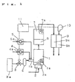
- Fig. 2 is a diagram showing the system configuration of a fuel cell electric power generating system according to embodiment 2 of the present invention.
- Like reference numerals designate like parts throughout embodiments 1 and 2 for the purpose of omitting the descriptions thereof.
- Reference numeral 12 designates an exhaust hydrogen connecting pipe for supplying a hydrogen off-gas exhausted from the hydrogen electrode 9a of the fuel cell 9 to the burner 2a.
- this embodiment 2 first purges the hydrogen-rich gas using steam at the time of the stoppage of the electric power generating operation like the embodiment 1, the embodiment 2 stops the water supply to the reformer 1 at the time the steam reaches the burner 2a and then purges the steam by means of air and, hence, hydrogen is completely burned out at the time of the stoppage of the water supply to the reformer 1, thus ensuring higher safety.
- the reformer 1 produces hydrogen-rich gas through the reforming reaction of the steam reforming system utilizing the source gas (hydrocarbon) and steam
- the reformer 1 may be constructed to produce hydrogen-rich gas through a reforming reaction of the system which does not utilize steam, for example, the partial oxidation system.
- water is supplied to the reformer 1 from the water supplying means 4 in order to generate steam for reforming reaction with the source gas (hydrocarbon) as well as to generate steam for purging the hydrogen-rich gas after the stoppage of electric power generation.
- the source gas hydrogen
- the water supply source for the generation of steam to be used in the reforming reaction and the water supply source for the generation of steam to be used to purge the hydrogen-rich gas may be provided separately from each other.
- Fig. 3 is a diagram showing the system configuration of a fuel cell electric power generating system according to embodiment 3 of the present invention.
- Like reference numerals designate like parts throughout embodiments 1 and 3 for the purpose of omitting the descriptions thereof.
- the carbon monoxide eliminator 7 is of the selective oxidation system which allows carbon monoxide and air to react with each other selectively.
- the selective oxidation system in general, requires the supply of air to the carbon monoxide eliminator 7.
- the air pump 5a as the air supplying means 5 also serves as an air supplying device for supplying air to the carbon monoxide eliminator 7.
- Switching means 13 appropriately switches air supply to the carbon monoxide eliminator 7 or to the upstream 1b of the reformer 1.
- embodiment 3 supplies air for purging steam by means of the air pump 5a at the time of the stoppage of the electric power generating operation like the embodiment 1, the embodiment 3 utilizes the air pump 5a even during the electric power generating operation by switching the air supply therefrom to the carbon monoxide eliminator 7 by means of the switching means 13, thereby allowing the carbon monoxide eliminating reaction at the carbon monoxide eliminator 7 to proceed continuously.
- the air pump 5a as the air supplying means 5 is used as the source for supplying air to the carbon monoxide eliminator 7 as well as the source for supplying air to the reformer 1 after the stoppage of electric power generation in the embodiment described above, the air supply source for the carbon monoxide eliminator 7 and the air supply source for the reformer 1 may be provided separately from each other.
- any one of the embodiments of the present invention provides a fuel cell electric power generating system which does not permit hydrogen-rich gas to stay within the path after the stoppage of the electric power generating operation and hence prevents explosion of hydrogen, thereby ensuring safety.
- the fuel cell electric power generating system has a structure for purging the hydrogen-rich gas by means of steam, the system need not be provided with any nitrogen equipment, such as a nitrogen cylinder , which is needed by the prior art to perform the purging operation using nitrogen.
- the fuel cell electric power generation system according to the present invention is used in, for example, a stationary-type dispersed power generation system for home use or a power source for electric vehicle, it is possible to make the equipment compact and to decrease the initial cost. Further, since there is no need to replace or replenish such a nitrogen cylinder, it is also possible to decrease the running cost.
- the present invention makes it possible to provide a fuel cell electric power generating system which purges a hydrogen-rich gas that remains in the fuel cell electric power generating system after the electric power generation performed by a fuel cell has been stopped without using nitrogen gas, as well as to provide a method of stopping fuel cell electric power generation.
Landscapes
- Engineering & Computer Science (AREA)
- Chemical & Material Sciences (AREA)
- Life Sciences & Earth Sciences (AREA)
- Manufacturing & Machinery (AREA)
- Sustainable Development (AREA)
- Sustainable Energy (AREA)
- Chemical Kinetics & Catalysis (AREA)
- Electrochemistry (AREA)
- General Chemical & Material Sciences (AREA)
- Combustion & Propulsion (AREA)
- Fuel Cell (AREA)
Abstract
Description
in stopping the operation of said fuel cell, the supply of said source gas to said reformer is stopped and the hydrogen-rich gas remaining within the fuel cell electric power generating system, steam, and said purging air are passed in this order.
subsequently, after lapse of a predetermined time, said purging air is supplied to said reformer by said first air supplying means.
said reformer produces said hydrogen-rich gas by utilizing said steam also.
said fuel cell is supplied with hydrogen-rich gas from which carbon monoxide is already eliminated by said carbon monoxide eliminator.
said first air supplying means functions also as said second air supplying means and
switching means is provided of switching a receiver of the supply of air from said first air supplying means to said reformer or said carbon monoxide eliminator.
the method comprising, in stopping the operation of said fuel cell, stopping the supply of said source gas to said reformer and passing the hydrogen-rich gas remaining within a fuel cell electric power generating system, steam, and said purging air in this order.
subsequently, after lapse of a predetermined time, said purging air is supplied to said reformer by said first air supplying means.
Claims (14)
- A fuel cell electric power generating system comprising a reformer producing hydrogen-rich gas by utilizing a source gas, source gas supplying means of supplying said source gas to said reformer, first air supplying means of supplying purging air to said reformer, and a fuel cell generating electric power by utilizing the hydrogen-rich gas produced at the reformer and air for electric power generation supplied from outside, wherein
in stopping the operation of said fuel cell, the supply of said source gas to said reformer is stopped and the hydrogen-rich gas remaining within the fuel cell electric power generating system, steam, and said purging air are passed in this order. - The fuel cell electric power generating system according to claim 1, wherein when the supply of said source gas to said reformer is stopped, steam is supplied to said reformer or water is supplied to said reformer and heated to generate steam, and
subsequently, after lapse of a predetermined time, said purging air is supplied to said reformer by said first air supplying means. - The fuel cell electric power generating system according to claim 2, wherein said predetermined time means a time taken for steam to purge the hydrogen-rich gas present within the fuel cell electric power generating system substantially completely.
- The fuel cell electric power generating system according to claim 2, wherein said predetermined time means a time sufficient to provide a predetermined amount of steam between said hydrogen-rich gas and said purging air so as to avoid a dangerous state resulting from contact between said hydrogen-rich gas present within the fuel cell electric power generating system and said purging air.
- The fuel cell electric power generating system according to any one of claims 1 to 4, wherein said reformer comprises water supplying means of supplying water for producing hydrogen to said reformer and heating means of heating said reformer to turn said water for producing hydrogen into steam; and
said reformer produces said hydrogen-rich gas by utilizing said steam also. - The fuel cell electric power generating system according to claim 5, wherein steam is generated by heating said water for producing hydrogen even after the operation of the fuel cell is stopped.
- The fuel cell electric power generating system according to claim 5 or 6, wherein said heating means use hydrogen off-gas exhausted from said fuel cell as a fuel.
- The fuel cell electric power generating system according to claim 7, wherein after steam reaches said heating means, the supply of said water for producing hydrogen to said reformer is stopped, while said purging air is supplied to said reformer.
- The fuel cell electric power generating system according to any one of claims 1 to 8, further comprising a carbon monoxide eliminator located downstream of said reformer for eliminating carbon monoxide contained in the hydrogen-rich gas produced at the reformer, and second air supplying means of supplying air for eliminating carbon monoxide to said carbon monoxide eliminator, wherein
said fuel cell is supplied with hydrogen-rich gas from which carbon monoxide is already eliminated by said carbon monoxide eliminator. - The fuel cell electric power generating system according to claim 9, wherein
said first air supplying means functions also as said second air supplying means and
switching means is provided of switching a receiver of the supply of air from said first air supplying means to said reformer or said carbon monoxide eliminator. - A method of stopping fuel cell electric power generation, which is employed after electric power generation performed using a reformer producing hydrogen-rich gas by utilizing a source gas, source gas supplying means of supplying said source gas to said reformer, first air supplying means of supplying purging air to said reformer, and a fuel cell generating electric power by utilizing the hydrogen-rich gas produced at the reformer and air for electric power generation supplied from outside,
the method comprising, in stopping the operation of said fuel cell, stopping the supply of said source gas to said reformer and passing the hydrogen-rich gas remaining within a fuel cell electric power generating system, steam, and said purging air in this order. - The method of stopping fuel cell electric power generation according to claim 11, wherein when the supply of said source gas to said reformer is stopped, steam is supplied to said reformer or water is supplied to said reformer and heated to generate steam, and
subsequently, after lapse of a predetermined time, said purging air is supplied to said reformer by said first air supplying means. - The method of stopping fuel cell electric power generation according to claim 12, wherein said predetermined time means a time taken for steam to purge the hydrogen-rich gas present within the fuel cell electric power generating system substantially completely.
- The method of stopping fuel cell electric power generation according to claim 12, wherein said predetermined time means a time sufficient to provide a predetermined amount of steam between said hydrogen-rich gas and said purging air so as to avoid a dangerous state resulting from contact between said hydrogen-rich gas present within the fuel cell electric power generating system and said purging air.
Applications Claiming Priority (3)
| Application Number | Priority Date | Filing Date | Title |
|---|---|---|---|
| JP2000177938 | 2000-06-14 | ||
| JP2000177938 | 2000-06-14 | ||
| PCT/JP2001/004960 WO2001097312A1 (en) | 2000-06-14 | 2001-06-12 | Fuel cell power generation system, and fuel cell power generation interrupting method |
Publications (2)
| Publication Number | Publication Date |
|---|---|
| EP1291948A1 true EP1291948A1 (en) | 2003-03-12 |
| EP1291948A4 EP1291948A4 (en) | 2004-10-20 |
Family
ID=18679457
Family Applications (1)
| Application Number | Title | Priority Date | Filing Date |
|---|---|---|---|
| EP01938610A Withdrawn EP1291948A4 (en) | 2000-06-14 | 2001-06-12 | FUEL CELL POWER GENERATION SYSTEM AND METHOD FOR INTERRUPTING THE POWER GENERATION OF A FUEL CELL |
Country Status (6)
| Country | Link |
|---|---|
| US (1) | US7432004B2 (en) |
| EP (1) | EP1291948A4 (en) |
| JP (1) | JP3686062B2 (en) |
| KR (1) | KR100481425B1 (en) |
| CN (1) | CN1255892C (en) |
| WO (1) | WO2001097312A1 (en) |
Cited By (5)
| Publication number | Priority date | Publication date | Assignee | Title |
|---|---|---|---|---|
| EP1501147A1 (en) * | 2003-07-24 | 2005-01-26 | Matsushita Electric Industrial Co., Ltd. | Fuel cell power generation system |
| EP1542303A2 (en) | 2003-12-12 | 2005-06-15 | Matsushita Electric Industrial Co., Ltd. | Fuel cell system |
| EP1270510A3 (en) * | 2001-06-20 | 2005-11-09 | Ballard Power Systems AG | Process for improving the cold start behaviour of selective CO-oxidation catalysts |
| WO2011006964A1 (en) * | 2009-07-16 | 2011-01-20 | Avl List Gmbh | Method for operating a high-temperature fuel cell |
| US8728675B2 (en) | 2004-11-08 | 2014-05-20 | Panasonic Corporation | Fuel cell system |
Families Citing this family (19)
| Publication number | Priority date | Publication date | Assignee | Title |
|---|---|---|---|---|
| JP2002179401A (en) * | 2000-12-11 | 2002-06-26 | Toyota Motor Corp | Method of shutting down operation of hydrogen gas generation system |
| JP2002231293A (en) | 2001-01-31 | 2002-08-16 | Toshiba Corp | Purge device and method for fuel cell system |
| US7192669B2 (en) * | 2001-11-30 | 2007-03-20 | Matsushita Electric Industrial Co., Ltd. | System and method of fuel cell power generation |
| US7081144B2 (en) * | 2003-04-04 | 2006-07-25 | Texaco Inc. | Autothermal reforming in a fuel processor utilizing non-pyrophoric shift catalyst |
| JP2005093115A (en) * | 2003-09-12 | 2005-04-07 | Matsushita Electric Ind Co Ltd | Fuel cell power generator and its operation method |
| US7615296B2 (en) * | 2004-08-06 | 2009-11-10 | Panasonic Corporation | Fuel cell system |
| US7282287B2 (en) * | 2004-11-24 | 2007-10-16 | Utc Power Corporation | Purging water with reactant air pump powered by operational fuel cell system during shutdown |
| JP2006228553A (en) * | 2005-02-17 | 2006-08-31 | Mitsubishi Electric Corp | Operation method of fuel cell |
| JP5063340B2 (en) * | 2005-02-18 | 2012-10-31 | パナソニック株式会社 | Fuel cell system and operation method thereof |
| JP4593311B2 (en) * | 2005-02-24 | 2010-12-08 | 三菱電機株式会社 | Fuel cell power generation system and method for stopping the same |
| US8945750B2 (en) * | 2005-05-13 | 2015-02-03 | Canon Kabushiki Kaisha | Electronic apparatus, control method and program thereof, and battery for operating electronic apparatus |
| US8813101B2 (en) * | 2007-03-28 | 2014-08-19 | Microsoft Corporation | Software technique to correlate conceptually similar entities |
| CN101682066B (en) * | 2008-03-12 | 2014-03-12 | 松下电器产业株式会社 | Fuel cell system |
| JP4893719B2 (en) * | 2008-09-22 | 2012-03-07 | トヨタ自動車株式会社 | Method for shutting down hydrogen gas generation system |
| WO2010087167A1 (en) * | 2009-01-27 | 2010-08-05 | パナソニック株式会社 | Fuel processing device, fuel cell system provided therewith, and method for operating a fuel processing device |
| US9537160B2 (en) * | 2012-02-15 | 2017-01-03 | GM Global Technology Operations LLC | Operational method for a simplified fuel cell system |
| CN103682396B (en) * | 2012-09-06 | 2016-09-28 | 上海汽车集团股份有限公司 | Hydrogen management method when fuel-cell vehicle hydrogen-feeding system quits work |
| CN111785995B (en) * | 2020-06-16 | 2023-05-23 | 国鸿氢能科技(嘉兴)股份有限公司 | Purging pipeline system of water-guiding bipolar plate fuel cell |
| CN111952636A (en) * | 2020-08-05 | 2020-11-17 | 河南豫氢动力有限公司 | Low-temperature shutdown purging method for vehicle fuel cell system |
Family Cites Families (10)
| Publication number | Priority date | Publication date | Assignee | Title |
|---|---|---|---|---|
| US4046956A (en) * | 1976-05-27 | 1977-09-06 | United Technologies Corporation | Process for controlling the output of a selective oxidizer |
| JPS6188461A (en) | 1984-10-05 | 1986-05-06 | Fuji Electric Co Ltd | Method of starting and stopping fuel cell power generation system |
| JPS6313277A (en) | 1986-07-03 | 1988-01-20 | Fuji Electric Co Ltd | In-system gas replacement of fuel cell |
| JP2972261B2 (en) | 1990-03-07 | 1999-11-08 | 大阪瓦斯株式会社 | Nitrogen purge method and heating method for fuel cell power generation system |
| JP2931372B2 (en) | 1990-06-18 | 1999-08-09 | 三菱電機株式会社 | Operating method of fuel cell power generation system |
| US5178969A (en) | 1990-07-06 | 1993-01-12 | Kabushiki Kaisha Toshiba | Fuel cell powerplant system |
| JPH0878037A (en) * | 1994-08-31 | 1996-03-22 | Aqueous Res:Kk | Fuel cell power generating system and its operation method |
| JP3911796B2 (en) | 1997-10-07 | 2007-05-09 | 日産自動車株式会社 | Fuel cell system and control method thereof |
| US5985474A (en) * | 1998-08-26 | 1999-11-16 | Plug Power, L.L.C. | Integrated full processor, furnace, and fuel cell system for providing heat and electrical power to a building |
| US6828048B2 (en) * | 2001-11-06 | 2004-12-07 | Utc Fuel Cells, Llc | Shut-down procedure for fuel cell fuel processing system |
-
2001
- 2001-06-12 US US10/130,468 patent/US7432004B2/en not_active Expired - Fee Related
- 2001-06-12 WO PCT/JP2001/004960 patent/WO2001097312A1/en not_active Ceased
- 2001-06-12 JP JP2002511412A patent/JP3686062B2/en not_active Expired - Lifetime
- 2001-06-12 CN CNB018105246A patent/CN1255892C/en not_active Expired - Fee Related
- 2001-06-12 KR KR10-2002-7016983A patent/KR100481425B1/en not_active Expired - Fee Related
- 2001-06-12 EP EP01938610A patent/EP1291948A4/en not_active Withdrawn
Cited By (7)
| Publication number | Priority date | Publication date | Assignee | Title |
|---|---|---|---|---|
| EP1270510A3 (en) * | 2001-06-20 | 2005-11-09 | Ballard Power Systems AG | Process for improving the cold start behaviour of selective CO-oxidation catalysts |
| EP1501147A1 (en) * | 2003-07-24 | 2005-01-26 | Matsushita Electric Industrial Co., Ltd. | Fuel cell power generation system |
| EP1542303A2 (en) | 2003-12-12 | 2005-06-15 | Matsushita Electric Industrial Co., Ltd. | Fuel cell system |
| EP1542303A3 (en) * | 2003-12-12 | 2009-03-04 | Panasonic Corporation | Fuel cell system |
| US8530104B2 (en) | 2003-12-12 | 2013-09-10 | Panasonic Corporation | Method of operating a fuel cell system |
| US8728675B2 (en) | 2004-11-08 | 2014-05-20 | Panasonic Corporation | Fuel cell system |
| WO2011006964A1 (en) * | 2009-07-16 | 2011-01-20 | Avl List Gmbh | Method for operating a high-temperature fuel cell |
Also Published As
| Publication number | Publication date |
|---|---|
| KR20030008162A (en) | 2003-01-24 |
| US20030054212A1 (en) | 2003-03-20 |
| KR100481425B1 (en) | 2005-04-08 |
| JP3686062B2 (en) | 2005-08-24 |
| CN1432203A (en) | 2003-07-23 |
| CN1255892C (en) | 2006-05-10 |
| US7432004B2 (en) | 2008-10-07 |
| EP1291948A4 (en) | 2004-10-20 |
| WO2001097312A1 (en) | 2001-12-20 |
Similar Documents
| Publication | Publication Date | Title |
|---|---|---|
| US7432004B2 (en) | Fuel cell electric power generating system and method of stopping fuel cell electric power generation | |
| US8486572B2 (en) | System and method of fuel cell power generation | |
| EP1153454B1 (en) | Purged anode, low effluent fuel cell | |
| US8530104B2 (en) | Method of operating a fuel cell system | |
| JP4724029B2 (en) | Method for shutting down reformer | |
| JPWO2001097312A1 (en) | Fuel cell power generation system and fuel cell power generation stopping method | |
| US7033687B2 (en) | Fuel cell power generation system and method of controlling fuel cell power generation | |
| US8728675B2 (en) | Fuel cell system | |
| JP5194373B2 (en) | Reformer | |
| US6413662B1 (en) | Fuel cell system shutdown with anode pressure control | |
| JP4884773B2 (en) | Fuel cell power generation system | |
| JP2003306309A (en) | Method for operating hydrogen-containing gas-producing apparatus | |
| KR20070032162A (en) | Purge device of fuel cell | |
| JP4024543B2 (en) | Fuel cell power generation system | |
| KR100820664B1 (en) | Fuel processor and its method | |
| JP2020015932A (en) | Hydrogen generation system and method for operating the same | |
| JP2003100332A (en) | Fuel cell power generation system | |
| KR20140047222A (en) | Inert gas purging system for fuel cell system of a ship | |
| JP2024123569A (en) | Fuel cell systems, hydrogen generators | |
| JP5350750B2 (en) | Fuel cell system |
Legal Events
| Date | Code | Title | Description |
|---|---|---|---|
| PUAI | Public reference made under article 153(3) epc to a published international application that has entered the european phase |
Free format text: ORIGINAL CODE: 0009012 |
|
| 17P | Request for examination filed |
Effective date: 20020510 |
|
| AK | Designated contracting states |
Kind code of ref document: A1 Designated state(s): AT BE CH CY DE DK ES FI FR GB GR IE IT LI LU MC NL PT SE TR Designated state(s): AT BE CH CY DE DK ES FI FR GB GR IE IT LI LU MC NL PT SE TR |
|
| RBV | Designated contracting states (corrected) |
Designated state(s): AT BE CH CY DE FR GB IT LI |
|
| A4 | Supplementary search report drawn up and despatched |
Effective date: 20040903 |
|
| 17Q | First examination report despatched |
Effective date: 20050517 |
|
| GRAP | Despatch of communication of intention to grant a patent |
Free format text: ORIGINAL CODE: EPIDOSNIGR1 |
|
| RBV | Designated contracting states (corrected) |
Designated state(s): DE FR GB IT |
|
| STAA | Information on the status of an ep patent application or granted ep patent |
Free format text: STATUS: THE APPLICATION IS DEEMED TO BE WITHDRAWN |
|
| 18D | Application deemed to be withdrawn |
Effective date: 20070503 |