EP1291864B1 - Transporting data cartridges - Google Patents
Transporting data cartridges Download PDFInfo
- Publication number
- EP1291864B1 EP1291864B1 EP02256248A EP02256248A EP1291864B1 EP 1291864 B1 EP1291864 B1 EP 1291864B1 EP 02256248 A EP02256248 A EP 02256248A EP 02256248 A EP02256248 A EP 02256248A EP 1291864 B1 EP1291864 B1 EP 1291864B1
- Authority
- EP
- European Patent Office
- Prior art keywords
- cartridge
- assembly
- pivot
- data
- drive
- Prior art date
- Legal status (The legal status is an assumption and is not a legal conclusion. Google has not performed a legal analysis and makes no representation as to the accuracy of the status listed.)
- Expired - Lifetime
Links
- 230000032258 transport Effects 0.000 description 72
- 238000006073 displacement reaction Methods 0.000 description 5
- 230000003287 optical effect Effects 0.000 description 4
- 238000006243 chemical reaction Methods 0.000 description 2
- 238000013500 data storage Methods 0.000 description 2
- 230000000452 restraining effect Effects 0.000 description 2
- 230000002441 reversible effect Effects 0.000 description 2
- 230000005540 biological transmission Effects 0.000 description 1
- 230000010354 integration Effects 0.000 description 1
- 238000004519 manufacturing process Methods 0.000 description 1
- 210000003813 thumb Anatomy 0.000 description 1
Images


Classifications
-
- G—PHYSICS
- G11—INFORMATION STORAGE
- G11B—INFORMATION STORAGE BASED ON RELATIVE MOVEMENT BETWEEN RECORD CARRIER AND TRANSDUCER
- G11B17/00—Guiding record carriers not specifically of filamentary or web form, or of supports therefor
- G11B17/22—Guiding record carriers not specifically of filamentary or web form, or of supports therefor from random access magazine of disc records
Definitions
- the invention pertains to transporting data cartridges and to the storage of data cartridges in cartridge libraries, and more particularly, to the integration and expansion of such libraries.
- DLT cartridges data cartridges
- Such data storage systems are often referred to as “cartridge libraries", particularly if they can accommodate a large number of data cartridges.
- a cartridge library may also be provided with a movable cartridge-engaging assembly or "picker” for transporting data cartridges between a library's various cartridge-receiving devices (e.g., between cartridge storage racks and cartridge drives).
- a typical cartridge-engaging assembly may also be provided with a plunge mechanism or "thumb assembly” for engaging the various data cartridges contained in the cartridge-receiving devices and drawing them into the cartridge-engaging assembly.
- a positioning system associated with the cartridge-engaging assembly may be used to move the cartridge-engaging assembly between the various cartridge-receiving devices.
- Cartridge libraries of the type described above are usually connected to a host computer system that reads and writes the data cartridges. For example, if the host computer system issues a request for data contained on a particular data cartridge, a control system associated with the cartridge library will actuate the positioning system to move the cartridge-engaging assembly along the cartridge storage racks until the cartridge-engaging assembly is positioned adjacent a desired data cartridge. The plunge mechanism associated with the cartridge-engaging assembly may then extend, engage the data cartridge, remove the data cartridge from its cartridge storage rack, and then retract to draw the data cartridge into the cartridge-engaging assembly. Thereafter, the positioning system may be actuated to move the cartridge-engaging assembly to an appropriate cartridge drive.
- the plunge mechanism may extend to insert the selected data cartridge into the cartridge drive so that the host computer may thereafter read and/or write the data cartridge.
- the plunge mechanism may be actuated to remove the data cartridge from the cartridge drive, and the cartridge-engaging assembly may be actuated to return the data cartridge to its cartridge storage rack.
- Document EP 407 305 discloses the features of the preamble of claim 1 and in particular:
- the inventors have devised what they believe to be novel, an apparatus for transporting data cartridges between adjacent cartridge libraries.
- the storage capacity of a single cartridge library may be increased by providing access to additional cartridge storage racks and/or additional cartridge drives.
- increasing the number of cartridge storage racks associated with the library can provide for more efficient use of the library' s drives.
- increasing the number of drives associated with the library can provide for more efficient access to the library' s data. Even when a library' s access to cartridge storage racks and drives are increased in a proportional manner, the mere association of more storage racks and more drives is likely to improve the use of, and access to, a library' s components and data.
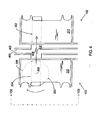
- FIG. 1 illustrates two adjacent cartridge libraries 104, 106.
- Each cartridge library 104, 106 comprises a number of modules 100, 102, 108-118 that are stacked and integrated to form a single, higher capacity, cartridge library 104, 106.
- the number of modules 100, 108-112 that may be stacked to form a single cartridge library 104 is limited to a relatively small number of modules (e.g., seven modules).
- each module 100 comprises two drawers 120, 122, with each drawer 120, 122 holding two cartridge magazines. Each cartridge magazine holds five data cartridges so that each of the FIG.
- cartridge libraries 104, 106 holds up to 80 data cartridges (i.e., 4 modules x 2 drawers/module x 2 magazines/drawer x 5 cartridges/magazine). If access to more than the 80 data cartridges held by one cartridge library 104 is desired, an additional cartridge library 106 may be acquired.
- a disadvantage of the FIG. 1 library system is that the two adjacent cartridge libraries 104, 106 operate distinctly.
- each of the cartridge libraries 104, 106 must comprise its own set of drives, even though a library user may only need to access a small number of cartridges at any one time.
- access to a particular data cartridge may be limited by the availability of drives in a particular one of the cartridge libraries 104, 106, even though the other cartridge library may have drives that remain unused.
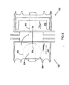
- FIG. 2 illustrates a cross-section of the FIG. 1 cartridge libraries 104, 106, wherein adjacent modules 100, 102 of the cartridge libraries 104, 106 function as independent systems.
- the modules 100, 102 are shown to be constructed in a similar manner, but they need not be.
- Each module 100, 102 (or “cartridge library” as they will be hereinafter referred to) may comprise a cartridge-engaging assembly or "picker" 200 for transferring data cartridges 202 between one or more cartridge-receiving devices 204-210 mounted within the cartridge library 100.
- cartridge storage racks 204, 206 will be designed to hold a number of cartridge magazines 212, 214, 216, 218, with each magazine 212-218 holding a predetermined subset of data cartridges 202, 220-226. In this manner, it is easier to add and/or remove data cartridges 202, 220-226 from a cartridge library 100.
- the cartridge positioning system 248 may be of the type shown and described in U.S. Pat. No. 6,025,972 (referred to supra).
- the cartridge positioning system 248 disclosed therein may comprise a generally rectangularly-shaped structure having a pair of opposed side portions 228 and 230 and an end portion 232.
- a pair of cartridge storage racks 204, 206 may be positioned adjacent the two opposed sides 228, 230 of the cartridge positioning system 248.
- a pair of cartridge read/write devices 208, 210 may be positioned adjacent the end 232 of the cartridge positioning system 248.
- the cartridge positioning system 248 may also comprise a lower plate 234 having a U-shaped guide member or channel 236 formed therein for guiding the cartridge-engaging assembly 200 along a generally U-shaped path 238 so that the cartridge-engaging assembly 200 may access the data cartridges 202, 220-226 contained in the various cartridge storage racks 204, 206 and cartridge read/write devices 208, 210.
- the cartridge-engaging assembly 200 may be moved along the U-shaped guide member 236 by an actuator system 246.
- the actuator system 246 may move the cartridge-engaging assembly 200 between a first position 240 adjacent the first side portion 228 of the positioning system 248, a second position 240' adjacent the end portion 232 of the positioning system 248, and a third position 240" adjacent the second side portion 230 of the positioning system 248 (i.e., the cartridge-engaging assembly 200 may be moved along the generally U-shaped path 238).
- the actuator system 246 may comprise a rack-and-pinion drive system having a U-shaped gear rack 242 mounted adjacent the U-shaped guide member 236 in the lower plate 234.
- a lower pinion gear 244 may be mounted to the cartridge-engaging assembly 200 so that it engages the U-shaped gear rack 242.
- a suitable drive motor (not shown) may be used to drive the pinion gear 244 and thereby move the cartridge-engaging assembly 200 along the U-shaped path 238.
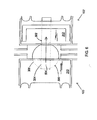
- FIG. 3 illustrates an alternative cross-section of the FIG. 1 cartridge libraries 100, 102, wherein one cartridge library 100 has been modified to hold a first data cartridge transport device 300, and the other cartridge library 102 has been modified to hold a second cartridge transport device 302.
- FIG. 4 illustrates an enlarged view of the FIG. 3 cartridge transport system 300, 302.
- the first data cartridge transport device 300 is a pivoting transport device
- the second data cartridge transport device 302 is a pass-through transport device.
- a data cartridge 202 stored in one of the cartridge libraries 100 may be retrieved by the cartridge-engaging assembly 200, placed in a cartridge sleeve 304 of the first data cartridge transport device 300, pivoted 180 degrees, ejected to the second data cartridge transport device 302, and then accessed by a cartridge-engaging assembly 306 of the other cartridge library 102.
- the transported data cartridge 202 is pivoted so that it is correctly oriented for engagement by the cartridge-engaging assembly 306 of the library 102 to which it is transported.
- the first data cartridge transport device 300 may comprise a pivot assembly 308 and a cartridge sleeve 304.
- the cartridge sleeve 304 is mounted to the pivot assembly 308 so that it pivots with the pivot assembly 308.
- the cartridge sleeve 304 is shown to pivot clockwise.
- a cartridge eject mechanism 800 (shown in FIGS. 8 & 9, but not in FIGS. 3 & 4) is operably associated with the cartridge sleeve 304 so that a data cartridge 202 may be ejected from the cartridge sleeve 304.
- the data cartridge transport device 300 also comprises a control system 802 (again shown in FIGS. 8 & 9, but not in FIGS. 3 & 4).
- the control system 802 is provided for alternately operating the pivot assembly 308 and the cartridge eject mechanism 800. Operation of the pivot assembly 308 causes the cartridge sleeve 304 to pivot, whereas operation of the cartridge eject mechanism 800 causes a data cartridge 202 to be ejected from the cartridge sleeve 304. Ejection of a data cartridge 202 from the first data cartridge transport device 300 allows the data cartridge 202 to be received by the second data cartridge transport device 302.
- the data cartridge transport system illustrated in FIG. 4 requires the first data cartridge transport device 300 to be an active device. That is, it must be capable of ejecting a cartridge 202 to the second data cartridge transport device 302.
- the second data cartridge transport device 302 may be constructed as either a passive or active device.
- a passive pass-through device is similar to a typical cartridge storage rack, in that data cartridges must be fully inserted into it, and it has no way of ejecting a data cartridge (i.e., cartridges must be extracted from it using a picker 306 or the like).
- An active pass-through device comprises an active cartridge-receiving mechanism for pulling a cartridge into the device, and/or an active cartridge eject mechanism for ejecting a cartridge from the device.
- An active pass-through device is advantageous in that 1) it may grab a data cartridge which has yet to be fully received into the device, and then pull the cartridge into the device, and/or 2) it may eject a data cartridge to thereby assist in enabling multi-directional cartridge transports (i.e., transport of a cartridge from a first cartridge library 100 to a second 102, and from the second cartridge library 102 to the first 100).
- the second data cartridge transport device 302 shown in FIG. 3 may also be a pivoting device 300. It might be desirable for the second data cartridge transport device 302 to be an active, pivoting device 300 if, for example, uniformity of manufacturing or 2-way cartridge transport is desired.
- the data cartridge transport devices 300, 302 shown in FIG. 3 are preferably sized to be held by cartridge storage racks 204, 206, similarly to cartridge magazines 212-218, 310, 312. In this manner, the transport devices 300, 302 may be purchased as accessories for adjacent cartridge libraries 100, 102, and may be inserted into and/or removed from a pair of adjacent cartridge libraries 100, 102 as necessary.
- holes 404, 406 may need to be cut into the walls 400, 402 of adjacent cartridge libraries 100, 102 so that data cartridges may be passed between the libraries. However, in some cases, these holes 404, 406 may already exist.
- the cartridge eject mechanism 800 of the first data cartridge transport device 500 may be used to fully insert a data cartridge 202 into the second data cartridge transport device 502 (or come "close enough” to inserting the data cartridge 202 fully into the second data cartridge transport device 502).
- the cartridge-engaging assembly 200 of the second cartridge library 102 i.e., the library 102 containing the second data cartridge transport device 502
- the first data cartridge transport device 500 will be able to grab the cartridge 200 by means of a cartridge-receiving mechanism (e.g., a cartridge eject mechanism 800 operated in a reverse direction).
- a cartridge-receiving mechanism e.g., a cartridge eject mechanism 800 operated in a reverse direction.
- FIG. 7 illustrates a second alternative to the FIG. 4 data cartridge transport system, wherein a pivoting data cartridge transport device 700 is mounted between two adjacent cartridge libraries 100, 102, and wherein each of the two adjacent cartridge libraries 100, 102 comprises a pass-through data cartridge transport device 702, 704.
- the pivoting data cartridge transport device 700 is similar to that disclosed in FIGS. 3 & 4, but for the location in which it is mounted.
- the FIG. 7 apparatus allows data cartridges to be transported from a first cartridge library 100 to a second cartridge library 102.
- both of the pass-through transport devices are active devices, cartridges may not only be transported from a first cartridge library 100 to a second 102, but also from the second cartridge library 102 to the first 100.
- FIGS. 8 & 9 illustrate (in elevation) a preferred embodiment of the pivoting data cartridge transport device 300 illustrated in FIGS. 3 & 4.
- the device is shown in eject mode.
- the device is shown in pivot mode.
- the device comprises a pivot assembly 308, a cartridge sleeve 304 (with entry and exit facing perpendicular to figure), a cartridge eject mechanism 800, and a control system 802.
- the cartridge sleeve 304 is mounted to the pivot assembly 308 so that it pivots with the pivot assembly 308.
- the cartridge eject mechanism 800 is operably associated with the cartridge sleeve 304 so that it may eject cartridges which are held by the cartridge sleeve 304.
- the control system 802 is provided for alternately operating the pivot assembly 308 (to thereby pivot the cartridge sleeve 304 and a cartridge held therein) and the cartridge eject mechanism 800 (to thereby eject a cartridge from the cartridge sleeve 304).
- the cartridge sleeve 304 Mounted to the pivot gear 804 is the cartridge sleeve 304. As shown in FIGS. 11 & 12, a channel 1100 is cut into the top surface of the pivot gear 804. Within this channel 1100 slides a blade 1200. The blade 1200 is mounted to the underside of the cartridge sleeve 304. When the blade 1200 is fit into the channel 1100, the cartridge sleeve 304 is mounted to the pivot gear 804 in such a manner that the cartridge sleeve 304 will pivot with the pivot gear 804. However, note that the channel 1100 is preferably of greater length than the blade 1200.
- the cartridge sleeve 304 may not only be pivoted with the pivot gear 804, but the cartridge sleeve 304 may also slide within the pivot gear 804 (for a purpose which has yet to be described).
- the cartridge sleeve 304 could comprise a channel, and the pivot gear 804 could comprise a blade.
- the pivot assembly 308 and cartridge sleeve 304 function as follows.
- the pivot 806 of the pivot assembly 308 is slid to a first position within its channel 808, as shown in FIG. 9, the pivot gear 804 is brought into engagement with a drive gear 812 of the control system 802.
- Operation of the control system 802 therefore causes the pivot gear 804 and cartridge sleeve 304 to pivot.
- the control system 802 stops driving the drive gear 812, and instead operates a clutch assembly 814, 816, 818.
- a noose 820 which encircles the pivot 806 of the pivot assembly 308 pushes the pivot 806 and pivot gear 804 away from the control system's drive gear 812 so as to disengage the pivot gear 804 from the drive gear 812 (see FIGS. 8, 9 & 13).
- the pivot 806 migrates toward its second position in the channel 808 of the pivot gear 804, as shown in FIG. 8.
- the cartridge sleeve 304 preferably does not move to a second position, as does the pivot gear 804. This is because the pivot gear 804 is preferably firmly attached to the pivot 806, but the cartridge sleeve is slidably mounted on the pivot gear 804 (i.e., via the channel 808 and blade 1200).
- the pivot gear 804 may be fixedly attached to the cartridge sleeve 304, and the drive gear 812 may be moved so as to disengage the pivot gear 804.
- the drive gear 812 might be moved in a variety of ways, including, by sliding in relation to the drive shaft 838, or by movement of the drive shaft 838 with respect to the bracket 842 which provides its support.
- the portion of the cartridge eject mechanism 800 which is mounted to the cartridge sleeve 304 comprises a plurality of ejection rollers 1000-1014 and a cartridge ejection gear train 1016-1030.
- Parts 1016-1022 of the gear train 1016-1030 are fixedly attached to the ejection rollers 1000-1014 so that the gear train 1016-1030 drives the ejection rollers 1000-1014.
- FIG. 810 Another portion of the cartridge eject mechanism 800 is mounted to the housing 810 in which the data cartridge transport device 300 is mounted.
- This second portion of the cartridge eject mechanism 800 comprises a drive shaft 822, a pair of drive gears 824, 832, and an idler gear 826.
- the drive shaft 822 may be supported by a pair of brackets 828, 830 which extend from the transport device's housing 810.
- One of the drive gears is preferably a pinion gear 824, and is fixedly and axially mounted to the drive shaft 822.
- the drive shaft 822 of the cartridge eject mechanism 800 may be coupled to a clutch assembly 814-818 of the control system 802 via a pivot, slip 837 or the like. In this manner, the drive shaft 822 may turn, yet the clutch assembly 814-818 may slide the drive shaft 822 within its brackets 828, 830 so as to engage or disengage the drive shaft's pinion gear 824 with a drive gear (e.g., a ring gear 834) of the control system 802.
- FIG. 8 illustrates engagement of the ring and pinion gears 834, 824.
- FIG. 9 illustrates disengagement of the ring and pinion gears 834, 824. Note that in FIG. 9, not only are the ring and pinion gears 834, 824 disengaged, but the drive gear 832 which operates the cartridge ejection gear train 1016-1030 is disengaged from the gear train 1016-1030.
- the drive shaft 822 of the cartridge eject mechanism 800 would necessarily comprise a pinion gear 824 and idler gear 826 which engaged the drive gear 834 from the operate direction (i.e., from the right in FIGS. 8 & 9).
- the drive motor 836 and drive shaft 838 of the drive assembly 812, 834-840 may be supported by a bracket 842 extending from the transport device's housing 810.
- the control system 802 may also comprise a clutch assembly 814-818.
- the clutch assembly 814-818 may in turn comprise a solenoid 814 and a pivot arm 818.
- the pivot arm 818 is preferably coupled to the solenoid 814, the pivot assembly 308, and the cartridge eject mechanism 800.
- the pivot arm 818 may be coupled to the solenoid 814 via a plunger 816; the pivot arm 818 may be coupled to the pivot assembly 308 via a noose 820; and the pivot arm 818 may be coupled to the cartridge eject mechanism 800 via a slip 837.
- the pivot point 844 of the pivot arm 818 may be mounted on a bracket 842 for supporting the solenoid 814, drive motor 836 and drive shaft 838 (with the pivot arm 818 extending through a cavity in the bracket 842).
- the clutch assembly 814-818 is movable between first and second positions.
- the first position is achieved when the solenoid 814 retracts its plunger 816 (see FIG. 9).
- the drive shaft 822 of the cartridge eject mechanism 800 is disengaged from the control system's drive assembly 812, 834-840, and 2) the pivot gear 804 of the pivot assembly 308 is engaged with the control system's drive assembly 812, 834-840.
- the cartridge sleeve 304 may be pivoted.
- the second position of the clutch assembly 814-818 is achieved when the solenoid 814 extends its plunger 816 (see FIG. 8).
- the drive shaft 822 of the cartridge eject mechanism 800 is engaged with the control system's drive assembly 812, 834-840, and 2) the pivot gear 804 of the pivot assembly 308 is disengaged from the control system's drive assembly 812, 834-840.
- a cartridge 202 may be ejected from the cartridge sleeve 304.
- the drive motor 836 and solenoid 814 may be powered by a backplane (not shown) to which other electronics of a cartridge library 100 are connected.
Landscapes
- Automatic Tape Cassette Changers (AREA)
- Automatic Disk Changers (AREA)
Applications Claiming Priority (2)
| Application Number | Priority Date | Filing Date | Title |
|---|---|---|---|
| US09/950,328 US6661602B2 (en) | 2001-09-10 | 2001-09-10 | Methods and apparatus for transporting data cartridges between adjacent cartridge libraries |
| US950328 | 2001-09-10 |
Publications (3)
| Publication Number | Publication Date |
|---|---|
| EP1291864A2 EP1291864A2 (en) | 2003-03-12 |
| EP1291864A3 EP1291864A3 (en) | 2004-01-07 |
| EP1291864B1 true EP1291864B1 (en) | 2007-04-04 |
Family
ID=25490282
Family Applications (1)
| Application Number | Title | Priority Date | Filing Date |
|---|---|---|---|
| EP02256248A Expired - Lifetime EP1291864B1 (en) | 2001-09-10 | 2002-09-10 | Transporting data cartridges |
Country Status (4)
| Country | Link |
|---|---|
| US (2) | US6661602B2 (enExample) |
| EP (1) | EP1291864B1 (enExample) |
| JP (1) | JP2003085852A (enExample) |
| DE (1) | DE60219250T2 (enExample) |
Families Citing this family (19)
| Publication number | Priority date | Publication date | Assignee | Title |
|---|---|---|---|---|
| US6648428B2 (en) * | 2001-04-18 | 2003-11-18 | Hewlett-Packard Development Company, L.P. | Reconfigurable data cartridge import/export drawer |
| US6985328B2 (en) * | 2002-07-09 | 2006-01-10 | Quantum Corporation | One and three quarters inch form factor tape cartridge autoloader |
| US7400469B2 (en) * | 2003-09-16 | 2008-07-15 | Spectra Logic Corporation | Magazine-based library |
| WO2006089133A2 (en) * | 2005-02-15 | 2006-08-24 | Duke University | Anti-cd19 antibodies and uses in oncology |
| US7328442B2 (en) | 2005-03-17 | 2008-02-05 | Quantum Corporation | Robotic corner negotiating systems and methods for automated storage libraries |
| AU2006244445B2 (en) * | 2005-05-05 | 2013-04-18 | Duke University | Anti-CD19 antibody therapy for autoimmune disease |
| WO2006133450A2 (en) * | 2005-06-08 | 2006-12-14 | Duke University | Anti-cd19 antibody therapy for the transplantation |
| CN103694349A (zh) * | 2006-09-08 | 2014-04-02 | 米迪缪尼有限公司 | 人源化抗cd19抗体及其在治疗癌症、移植病和自身免疫病中的应用 |
| DE102007056794B4 (de) * | 2007-11-23 | 2010-07-08 | Bdt Ag | Aufzugsystem für einen Speicherroboter |
| JP5402937B2 (ja) | 2008-09-30 | 2014-01-29 | 富士通株式会社 | ライブラリ装置とライブラリ装置の棚移動方法 |
| JP5710871B2 (ja) * | 2009-09-29 | 2015-04-30 | Necプラットフォームズ株式会社 | カートリッジ搬送装置、ライブラリ装置、およびライブラリシステム |
| US20120127607A1 (en) * | 2010-11-22 | 2012-05-24 | Spectra Logic Corporation | Efficient moves via repository |
| US8687315B2 (en) | 2011-05-11 | 2014-04-01 | International Business Machines Corporation | Data storage system using a media mobility unit (MMU), the MMU, and methods of use thereof |
| US8400728B2 (en) | 2011-05-23 | 2013-03-19 | Spectra Logic Corp. | Efficient moves via repository |
| US9368148B2 (en) | 2011-10-25 | 2016-06-14 | Spectra Logic, Corporation | Efficient moves via spare chamber |
| JP5983045B2 (ja) * | 2012-05-30 | 2016-08-31 | 富士通株式会社 | ライブラリ装置 |
| US9159357B2 (en) | 2013-08-14 | 2015-10-13 | Spectra Logic Corporation | Efficient moves via repository |
| US9093088B1 (en) | 2014-05-14 | 2015-07-28 | International Business Machines Corporation | Load balancing and space efficient big data tape management |
| US10783931B1 (en) * | 2019-06-20 | 2020-09-22 | Amazon Technologies, Inc. | Robotic device movement optimization in data storage library systems |
Family Cites Families (13)
| Publication number | Priority date | Publication date | Assignee | Title |
|---|---|---|---|---|
| US4998232A (en) * | 1988-11-30 | 1991-03-05 | Hewlett-Packard Company | Optical disk handling apparatus with flip latch |
| JPH0320059U (enExample) * | 1989-07-05 | 1991-02-27 | ||
| US5118664A (en) * | 1991-03-28 | 1992-06-02 | Bottom Line Industries, Inc. | Lost circulation material with rice fraction |
| DE69519261T2 (de) * | 1994-07-27 | 2001-03-01 | Fujitsu Ltd., Kawasaki | Automatische Datenspeicherungsbibliothek |
| KR100188966B1 (ko) | 1995-09-30 | 1999-06-01 | 윤종용 | 디스크 재생장치 및 그 작동방법 |
| US5760995A (en) | 1995-10-27 | 1998-06-02 | Quantum Corporation | Multi-drive, multi-magazine mass storage and retrieval unit for tape cartridges |
| US5781367A (en) | 1995-11-13 | 1998-07-14 | Advanced Digital Information Corporation | Library for storing data-storage media |
| US6025972A (en) | 1998-03-20 | 2000-02-15 | Hewlett-Packard Company | Multi-plane translating cartridge handling system |
| US6011669A (en) * | 1998-04-27 | 2000-01-04 | Storage Technology Corporation | Pass thru mechanism for transferring magnetic tape cartridges between automated cartridge library systems |
| US6438623B1 (en) * | 1999-04-16 | 2002-08-20 | Ampex Corporation | Transfer unit extending between two or more cabinets for expansion of tape library systems |
| US6327113B1 (en) * | 1999-12-08 | 2001-12-04 | Hewlett-Packard Company | Rotatable cartridge engaging assembly |
| US6488462B1 (en) * | 2000-01-12 | 2002-12-03 | Quantum Corporation | Transport mechanism for a storage system |
| US6693759B2 (en) * | 2000-11-10 | 2004-02-17 | Quantum Corporation | Compact form factor for an automated tape cartridge autoloader/library system |
-
2001
- 2001-09-10 US US09/950,328 patent/US6661602B2/en not_active Expired - Fee Related
-
2002
- 2002-09-05 JP JP2002259704A patent/JP2003085852A/ja active Pending
- 2002-09-10 EP EP02256248A patent/EP1291864B1/en not_active Expired - Lifetime
- 2002-09-10 DE DE60219250T patent/DE60219250T2/de not_active Expired - Lifetime
-
2003
- 2003-08-08 US US10/637,989 patent/US7199967B2/en not_active Expired - Fee Related
Also Published As
| Publication number | Publication date |
|---|---|
| US6661602B2 (en) | 2003-12-09 |
| JP2003085852A (ja) | 2003-03-20 |
| US20040032689A1 (en) | 2004-02-19 |
| EP1291864A3 (en) | 2004-01-07 |
| US20030048572A1 (en) | 2003-03-13 |
| DE60219250T2 (de) | 2008-02-28 |
| EP1291864A2 (en) | 2003-03-12 |
| US7199967B2 (en) | 2007-04-03 |
| DE60219250D1 (de) | 2007-05-16 |
Similar Documents
| Publication | Publication Date | Title |
|---|---|---|
| EP1291864B1 (en) | Transporting data cartridges | |
| JP3014751B2 (ja) | テープカートリッジ用自動ローダマガジン | |
| EP0709169B1 (en) | Accessor hand mechanism in library device | |
| US6469850B2 (en) | Automatic splaying picker finger | |
| KR19990067467A (ko) | 테이프 카트리지용 다중 드라이브 다중 매거진 대량 저장 및 검색 유니트 | |
| EP0944078A1 (en) | Cartridge engaging assembly with rack drive thumb actuator system | |
| US6231291B1 (en) | Method and apparatus for exchanging data cartridges in a jukebox data storage system | |
| US6643091B2 (en) | Automated data cartridge import/export drawer | |
| JP2003006966A (ja) | データ・カートリッジ交換装置 | |
| KR920004756Y1 (ko) | 디스크형 기록매체 재생장치 | |
| EP1107245A1 (en) | Rotatable cartridge engaging assembly | |
| EP1024487B1 (en) | Guide system in a cartridge picker assembly | |
| EP0877363B1 (en) | Data cartridge interlock and release system | |
| US7016144B2 (en) | Robot hand for transferring an article in a housing, and a library apparatus equipped with the robot hand for transferring and article stored in a rack | |
| EP0877362A2 (en) | Data cartridge caddy-to-storage rack interlock and release system | |
| US5892750A (en) | Multi-ported robotic shuttle for cartridge retrieval and insertion in a storage library subsystem | |
| EP1492104B1 (en) | Cartridge-handling apparatus for a media storage system | |
| JP2883013B2 (ja) | ライブラリ装置及びライブラリ装置のアクセッサハンド機構 | |
| US5815340A (en) | Apparatus and methods for cartridge retrieval and insertion in a storage library subsystem including a robotic shuttle having a sole rocker beam | |
| GB2383183A (en) | Dual passage cassette transfer apparatus | |
| US7483344B2 (en) | Compact picker systems and methods for automated storage libraries | |
| US6349891B1 (en) | Tape drive ejection assembly | |
| JP2002093016A (ja) | ディスク装置 | |
| JPH02306462A (ja) | カセット装填装置 |
Legal Events
| Date | Code | Title | Description |
|---|---|---|---|
| PUAI | Public reference made under article 153(3) epc to a published international application that has entered the european phase |
Free format text: ORIGINAL CODE: 0009012 |
|
| AK | Designated contracting states |
Kind code of ref document: A2 Designated state(s): AT BE BG CH CY CZ DE DK EE ES FI FR GB GR IE IT LI LU MC NL PT SE SK TR |
|
| AX | Request for extension of the european patent |
Extension state: AL LT LV MK RO SI |
|
| PUAL | Search report despatched |
Free format text: ORIGINAL CODE: 0009013 |
|
| AK | Designated contracting states |
Kind code of ref document: A3 Designated state(s): AT BE BG CH CY CZ DE DK EE ES FI FR GB GR IE IT LI LU MC NL PT SE SK TR |
|
| AX | Request for extension of the european patent |
Extension state: AL LT LV MK RO SI |
|
| 17P | Request for examination filed |
Effective date: 20040308 |
|
| AKX | Designation fees paid |
Designated state(s): DE FR GB |
|
| 17Q | First examination report despatched |
Effective date: 20050211 |
|
| GRAP | Despatch of communication of intention to grant a patent |
Free format text: ORIGINAL CODE: EPIDOSNIGR1 |
|
| GRAS | Grant fee paid |
Free format text: ORIGINAL CODE: EPIDOSNIGR3 |
|
| GRAA | (expected) grant |
Free format text: ORIGINAL CODE: 0009210 |
|
| AK | Designated contracting states |
Kind code of ref document: B1 Designated state(s): DE FR GB |
|
| REG | Reference to a national code |
Ref country code: GB Ref legal event code: FG4D |
|
| REF | Corresponds to: |
Ref document number: 60219250 Country of ref document: DE Date of ref document: 20070516 Kind code of ref document: P |
|
| ET | Fr: translation filed | ||
| PLBE | No opposition filed within time limit |
Free format text: ORIGINAL CODE: 0009261 |
|
| STAA | Information on the status of an ep patent application or granted ep patent |
Free format text: STATUS: NO OPPOSITION FILED WITHIN TIME LIMIT |
|
| 26N | No opposition filed |
Effective date: 20080107 |
|
| PGFP | Annual fee paid to national office [announced via postgrant information from national office to epo] |
Ref country code: GB Payment date: 20090929 Year of fee payment: 8 |
|
| PGFP | Annual fee paid to national office [announced via postgrant information from national office to epo] |
Ref country code: DE Payment date: 20090929 Year of fee payment: 8 |
|
| GBPC | Gb: european patent ceased through non-payment of renewal fee |
Effective date: 20100910 |
|
| REG | Reference to a national code |
Ref country code: FR Ref legal event code: ST Effective date: 20110531 |
|
| REG | Reference to a national code |
Ref country code: DE Ref legal event code: R119 Ref document number: 60219250 Country of ref document: DE Effective date: 20110401 |
|
| PG25 | Lapsed in a contracting state [announced via postgrant information from national office to epo] |
Ref country code: DE Free format text: LAPSE BECAUSE OF NON-PAYMENT OF DUE FEES Effective date: 20110401 Ref country code: FR Free format text: LAPSE BECAUSE OF NON-PAYMENT OF DUE FEES Effective date: 20100930 |
|
| PG25 | Lapsed in a contracting state [announced via postgrant information from national office to epo] |
Ref country code: GB Free format text: LAPSE BECAUSE OF NON-PAYMENT OF DUE FEES Effective date: 20100910 |
|
| PGFP | Annual fee paid to national office [announced via postgrant information from national office to epo] |
Ref country code: FR Payment date: 20091006 Year of fee payment: 8 |