EP1291557B1 - Verteilergetriebe für Fahrzeuge - Google Patents
Verteilergetriebe für Fahrzeuge Download PDFInfo
- Publication number
- EP1291557B1 EP1291557B1 EP02017341A EP02017341A EP1291557B1 EP 1291557 B1 EP1291557 B1 EP 1291557B1 EP 02017341 A EP02017341 A EP 02017341A EP 02017341 A EP02017341 A EP 02017341A EP 1291557 B1 EP1291557 B1 EP 1291557B1
- Authority
- EP
- European Patent Office
- Prior art keywords
- pinion
- power divider
- divider according
- toothed
- rim
- Prior art date
- Legal status (The legal status is an assumption and is not a legal conclusion. Google has not performed a legal analysis and makes no representation as to the accuracy of the status listed.)
- Expired - Lifetime
Links
- 230000005540 biological transmission Effects 0.000 claims description 7
- 230000009286 beneficial effect Effects 0.000 description 1
- 238000011161 development Methods 0.000 description 1
- 230000018109 developmental process Effects 0.000 description 1
- 239000002828 fuel tank Substances 0.000 description 1
Images



Classifications
-
- F—MECHANICAL ENGINEERING; LIGHTING; HEATING; WEAPONS; BLASTING
- F16—ENGINEERING ELEMENTS AND UNITS; GENERAL MEASURES FOR PRODUCING AND MAINTAINING EFFECTIVE FUNCTIONING OF MACHINES OR INSTALLATIONS; THERMAL INSULATION IN GENERAL
- F16C—SHAFTS; FLEXIBLE SHAFTS; ELEMENTS OR CRANKSHAFT MECHANISMS; ROTARY BODIES OTHER THAN GEARING ELEMENTS; BEARINGS
- F16C19/00—Bearings with rolling contact, for exclusively rotary movement
- F16C19/54—Systems consisting of a plurality of bearings with rolling friction
- F16C19/56—Systems consisting of a plurality of bearings with rolling friction in which the rolling bodies of one bearing differ in diameter from those of another
-
- B—PERFORMING OPERATIONS; TRANSPORTING
- B60—VEHICLES IN GENERAL
- B60K—ARRANGEMENT OR MOUNTING OF PROPULSION UNITS OR OF TRANSMISSIONS IN VEHICLES; ARRANGEMENT OR MOUNTING OF PLURAL DIVERSE PRIME-MOVERS IN VEHICLES; AUXILIARY DRIVES FOR VEHICLES; INSTRUMENTATION OR DASHBOARDS FOR VEHICLES; ARRANGEMENTS IN CONNECTION WITH COOLING, AIR INTAKE, GAS EXHAUST OR FUEL SUPPLY OF PROPULSION UNITS IN VEHICLES
- B60K17/00—Arrangement or mounting of transmissions in vehicles
- B60K17/22—Arrangement or mounting of transmissions in vehicles characterised by arrangement, location, or type of main drive shafting, e.g. cardan shaft
-
- B—PERFORMING OPERATIONS; TRANSPORTING
- B60—VEHICLES IN GENERAL
- B60K—ARRANGEMENT OR MOUNTING OF PROPULSION UNITS OR OF TRANSMISSIONS IN VEHICLES; ARRANGEMENT OR MOUNTING OF PLURAL DIVERSE PRIME-MOVERS IN VEHICLES; AUXILIARY DRIVES FOR VEHICLES; INSTRUMENTATION OR DASHBOARDS FOR VEHICLES; ARRANGEMENTS IN CONNECTION WITH COOLING, AIR INTAKE, GAS EXHAUST OR FUEL SUPPLY OF PROPULSION UNITS IN VEHICLES
- B60K17/00—Arrangement or mounting of transmissions in vehicles
- B60K17/34—Arrangement or mounting of transmissions in vehicles for driving both front and rear wheels, e.g. four wheel drive vehicles
-
- F—MECHANICAL ENGINEERING; LIGHTING; HEATING; WEAPONS; BLASTING
- F16—ENGINEERING ELEMENTS AND UNITS; GENERAL MEASURES FOR PRODUCING AND MAINTAINING EFFECTIVE FUNCTIONING OF MACHINES OR INSTALLATIONS; THERMAL INSULATION IN GENERAL
- F16H—GEARING
- F16H57/00—General details of gearing
- F16H57/02—Gearboxes; Mounting gearing therein
- F16H57/021—Shaft support structures, e.g. partition walls, bearing eyes, casing walls or covers with bearings
-
- F—MECHANICAL ENGINEERING; LIGHTING; HEATING; WEAPONS; BLASTING
- F16—ENGINEERING ELEMENTS AND UNITS; GENERAL MEASURES FOR PRODUCING AND MAINTAINING EFFECTIVE FUNCTIONING OF MACHINES OR INSTALLATIONS; THERMAL INSULATION IN GENERAL
- F16C—SHAFTS; FLEXIBLE SHAFTS; ELEMENTS OR CRANKSHAFT MECHANISMS; ROTARY BODIES OTHER THAN GEARING ELEMENTS; BEARINGS
- F16C2361/00—Apparatus or articles in engineering in general
- F16C2361/61—Toothed gear systems, e.g. support of pinion shafts
-
- Y—GENERAL TAGGING OF NEW TECHNOLOGICAL DEVELOPMENTS; GENERAL TAGGING OF CROSS-SECTIONAL TECHNOLOGIES SPANNING OVER SEVERAL SECTIONS OF THE IPC; TECHNICAL SUBJECTS COVERED BY FORMER USPC CROSS-REFERENCE ART COLLECTIONS [XRACs] AND DIGESTS
- Y10—TECHNICAL SUBJECTS COVERED BY FORMER USPC
- Y10T—TECHNICAL SUBJECTS COVERED BY FORMER US CLASSIFICATION
- Y10T74/00—Machine element or mechanism
- Y10T74/19—Gearing
- Y10T74/19642—Directly cooperating gears
- Y10T74/19688—Bevel
- Y10T74/19693—Motor vehicle drive
Definitions
- the present invention relates to a transfer case for vehicles according to the preamble of claim 1.
- the pinion shaft is in this transfer case with two double row Tandem angular contact ball bearings mounted, which employed in O arrangement are.
- the first angular contact ball bearing is directly on the pinion and the second in arranged a distance from the pinion on the pinion shaft.
- the pinion is so stored "on the fly”.
- the PTO shaft extends laterally offset to Vehicle center longitudinal plane. Accordingly, there is the transfer case also arranged eccentrically on the rear axle. Because of the off-center Arrangement of the transfer case are at the rear two different lengths of output shafts needed what a constructive Extra work and additional costs caused.
- the object of the invention is an improved transfer case for vehicles to create with laterally offset propeller shaft.
- the basic principle of the invention is a transfer case in which the ring gear of the ring gear and the meshing pinion on are arranged that side of the sprocket carrier of the ring gear, the facing away from the differential gear of the transfer case.
- simplified Expressed are the pinion and the ring gear of the ring gear in comparison to a conventional differential gear "mirrored” arranged, i. on the "other side” of the sprocket carrier of the ring gear.
- the pinion shaft has two hollow cylindrical Recess on, in each of which a pinion bearing is inserted.
- the one pinion bearing can directly "under” the pinion teeth and the other pinion bearings "just behind” the pinion teeth are arranged.
- the propeller shaft extends laterally offset from Center longitudinal axis of the vehicle, for example, 200mm to the side of it.
- the invention is then for "distance bridging" between offset arranged propeller shaft and the distributor gear in the area the rear axle provided a gear or a chain drive.
- the transfer case can therefore also be arranged in the middle of the vehicle when the Propeller shaft relatively far eccentrically. This has the great advantage that uses two equally long or even identical output shafts can be.
- Figure 1 shows a schematic representation of a Häachsverteilergetriebe a vehicle with a drive pinion 1, which meshes with a ring gear 2.
- the ring gear 2 is formed by a sprocket 3 and a sprocket carrier 4.
- the sprocket carrier 4 is rotatably attached to a housing 5 of a differential gear 6.
- the propeller shaft 9 is laterally, that is arranged offset in the direction of the longitudinal axis 12 of the output shafts 7, 8.
- the distance between the longitudinal axis 13 and the "center" 14 of the differential gear 6 and the transfer case is for example 200mm.
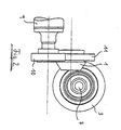
- Figure 2 shows a side view of the transfer case of Figure 1.
- the propeller shaft 9 extends below the output shafts 7, 8. This height difference is compensated by the gear stage 10, 11 and meshing with the ring gear 3 pinion 1.
- Figure 3 shows a schematic perspective view of the transfer case of Figures 1 and 2 . Again, the lateral offset and the height offset of the propeller shaft 9 are clearly visible.
- Figure 4 shows a schematic representation of a section through the transfer case in the region of the pinion 1 and the propeller shaft 9.
- the end of the propeller shaft 9 is connected to the gear 10, which here by two employees only schematically employed in O arrangement employed angular contact ball bearings 15, 16 is.
- the gear 10 meshes with the gear 11, which is integrally connected to the pinion 1 here.
- the pinion 1 is supported by two angular contact ball bearings, namely by a first angular contact ball bearing 1 and a second angular contact ball bearing 2, which also are employed in O arrangement.
- the pinion is 1 a "hollow pinion”.
- the first angular contact ball bearing 17 is in a recess 19
- the second angular contact ball bearing 18 is in a recess 20 of the pinion 1 arranged.
- the first angular contact ball bearing 17 sits directly under the pinion gear rim 21.
- the pinion bearing shown in Figure 4 differs quite fundamentally from the pinion bearings of conventional transfer cases.
- the pinion 1 is in fact not cantilevered.
- By the two angular contact ball bearings 17, 18, in particular by the immediately below the pinion gear 21 seated angular contact ball bearings 17 results in an extremely stiff pinion bearing. Due to the two-sided storage of the pinion 1 results over a cantilevered pinion a significant reduction in wear and a longer life and better transmission efficiency.
Landscapes
- Engineering & Computer Science (AREA)
- Mechanical Engineering (AREA)
- General Engineering & Computer Science (AREA)
- Chemical & Material Sciences (AREA)
- Combustion & Propulsion (AREA)
- Transportation (AREA)
- Retarders (AREA)
- General Details Of Gearings (AREA)
- Motor Power Transmission Devices (AREA)
- Gears, Cams (AREA)
- Arrangement And Driving Of Transmission Devices (AREA)
Description
- Figur 1
- eine schematische Draufsicht auf das Verteilergetriebe gemäß der Erfindung;
- Figur 2
- eine Seitenansicht des Verteilergetriebes der Figur 1;
- Figur 3
- eine schematische perspektivische Darstellung des Verteilergetriebes der Figuren 1 und 2; und
- Figur 4
- eine Schnittdarstellung des Verteilergetriebes entsprechend Figur 1.
Claims (13)
- Verteilergetriebe für Fahrzeuge mit
einem Ritzel (1), das mit einem Tellerrad (2) kämmt, welches durch einen Zahnkranz (3) und einen Zahnkranzträger (4) gebildet und zum Antrieb eines Ausgleichsgetriebes (6) vorgesehen ist,
wobei das Ritzel (1) und der Zahnkranz (3) des Tellerrades (2) auf derjenigen Seite des Zahnkranzträgers (4) angeordnet sind, die einer Mittelebene (14) des Ausgleichsgetriebes (6) abgewandt ist, wobei
das Ritzel (1) durch zwei unmittelbar im Bereich des Ritzels (1) angeordnete Lager (17, 18) gelagert ist, dadurch gekennzeichnet, dass
ein erstes Lager (17) unmittelbar im Bereich des Ritzelzahnkranzes (21) angeordnet ist und das zweite Lager (18) hinter dem Ritzelzahnkranz (21) angeordnet ist und
das Ritzel (1) hohlzylindrische Ausnehmungen (19, 20) aufweist, in denen die beiden Lager (17, 18) angeordnet sind. - Verteilergetriebe nach Anspruch 1, dadurch gekennzeichnet, dass der Zahnkranzträger (4) bezüglich des Ausgleichsgetriebes außermittig angeordnet ist.
- Verteilergetriebe nach Anspruch 1 oder 2, dadurch gekennzeichnet, dass zwei Abtriebswellen (7, 8) vorgesehen sind, die auf gegenüberliegenden Seiten vom Verteilergetriebe abzweigen.
- Verteilergetriebe nach Anspruch 3, dadurch gekennzeichnet, dass das Verteilergetriebe fahrzeugmittig angeordnet ist und dass die Abtriebswellen (7,8) gleich lang sind.
- Verteilergetriebe nach einem der Ansprüche 1 bis 4, dadurch gekennzeichnet, dass das Ritzel (1) über eine Gelenkwelle (9) angetrieben wird, die in einer Ebene verläuft, die im wesentlichen senkrecht zu den Abtriebswellen (7, 8) und seitlich versetzt bezüglich einer Mittelebene (14) des Verteilergetriebes verläuft.
- Verteilergetriebe nach einem der Ansprüche 1 bis 5, dadurch gekennzeichnet, dass die Gelenkwelle (9) bezüglich einer Fahrzeugmittellängsebene (14) um 150mm bis 250 mm seitlich versetzt angeordnet ist.
- Verteilergetriebe nach einem der Ansprüche 1 bis 6, dadurch gekennzeichnet, dass die Gelenkwelle (9) bezüglicher einer Fahrzeugmittellängsachse (14) 200mm seitlich versetzt angeordnet ist.
- Verteilergetriebe nach einem der vorangehenden Ansprüche, dadurch gekennzeichnet, dass das erste Lager (17) unmittelbar unter dem Ritzelzahnkranz (21) angeordnet ist.
- Verteilergetriebe nach einem der vorangehenden Ansprüche, dadurch gekennzeichnet, dass die Lager (17, 18) Schrägkugellager sind, die in O-Anordnung angeordnet sind.
- Verteilergetriebe nach einem der vorangehenden Ansprüche, dadurch gekennzeichnet, dass das Ritzel (1) über eine Drehmomentenübertragungseinrichtung (10, 11) mit der Gelenkwelle (9) verbunden ist.
- Verteilergetriebe nach Anspruch 10, dadurch gekennzeichnet, dass die Drehmomentenübertragungseinrichtung (10, 11) eine Zahnradstufe ist.
- Verteilergetriebe nach Anspruch 11, dadurch gekennzeichnet, dass ein Zahnrad (10) der Zahnradstufe mit einem Ende der Gelenkwelle (9) und das andere Zahnrad (11) mit dem Ritzel (1) verbunden ist.
- Verteilergetriebe nach Anspruch 10, dadurch gekennzeichnet, dass die Drehmomentenübertragungseinrichtung durch einen Kettentrieb gebildet ist.
Applications Claiming Priority (2)
| Application Number | Priority Date | Filing Date | Title |
|---|---|---|---|
| DE10143886A DE10143886C1 (de) | 2001-09-07 | 2001-09-07 | Verteilergetriebe für Fahrzeuge |
| DE10143886 | 2001-09-07 |
Publications (3)
| Publication Number | Publication Date |
|---|---|
| EP1291557A2 EP1291557A2 (de) | 2003-03-12 |
| EP1291557A3 EP1291557A3 (de) | 2004-08-04 |
| EP1291557B1 true EP1291557B1 (de) | 2005-12-28 |
Family
ID=7698046
Family Applications (1)
| Application Number | Title | Priority Date | Filing Date |
|---|---|---|---|
| EP02017341A Expired - Lifetime EP1291557B1 (de) | 2001-09-07 | 2002-08-02 | Verteilergetriebe für Fahrzeuge |
Country Status (5)
| Country | Link |
|---|---|
| US (1) | US6814176B2 (de) |
| EP (1) | EP1291557B1 (de) |
| JP (1) | JP2003139218A (de) |
| DE (2) | DE10143886C1 (de) |
| ES (1) | ES2254566T3 (de) |
Families Citing this family (4)
| Publication number | Priority date | Publication date | Assignee | Title |
|---|---|---|---|---|
| USD549731S1 (en) * | 2005-10-20 | 2007-08-28 | Dana Corporation | Vehicle differential case |
| US8381861B2 (en) * | 2008-03-20 | 2013-02-26 | American Axle & Manufacturing, Inc. | Power transfer unit with dual hypoid geartrain |
| DE102016219647A1 (de) * | 2016-10-10 | 2018-04-12 | Aktiebolaget Skf | Schrägkugellager und Getriebeanordnung |
| DE102017221603B4 (de) * | 2017-11-30 | 2020-03-19 | Ford Global Technologies, Llc | Seitliche Antriebswelle eines Antriebsstranges eines Kraftfahrzeuges mit außenliegendem Gleichlaufgelenk |
Family Cites Families (25)
| Publication number | Priority date | Publication date | Assignee | Title |
|---|---|---|---|---|
| US1185174A (en) * | 1915-05-15 | 1916-05-30 | Alanson P Brush | Differential gearing. |
| US1289531A (en) * | 1917-09-22 | 1918-12-31 | R & P Tractor Company | Vehicle drive mechanism. |
| US1884178A (en) | 1930-06-13 | 1932-10-25 | Singer Mfg Co | Sewing machine |
| US1984179A (en) * | 1933-07-24 | 1934-12-11 | Alexander S Diack | Vehicle driving means |
| US2693244A (en) * | 1950-06-15 | 1954-11-02 | Rockwell Spring & Axle Co | Multiwheeler with angle drive |
| US4148262A (en) * | 1973-05-22 | 1979-04-10 | Carl Hurth Maschinen-Und Zahnradfabrik | Railway vehicle drive |
| US4050534A (en) * | 1975-02-13 | 1977-09-27 | Eaton Corporation | Drive axle system useable in 6 × 6 vehicle |
| GB2106055B (en) * | 1981-07-31 | 1985-06-05 | Kubota Ltd | Tractor transmission arrangement |
| KR910000882B1 (ko) | 1984-01-21 | 1991-02-12 | 구보다 덱고오 가부시기가이샤 | 농업용 트랙터에 있어서의 차륜용 전동부의 구조 |
| US4781259A (en) * | 1985-10-25 | 1988-11-01 | Kanzaki Kokyukoki Mfg. Co. Ltd. | Axle driving apparatus |
| JP2537036B2 (ja) * | 1986-07-26 | 1996-09-25 | 富士重工業株式会社 | 自動変速機を備えた車両の終減速機装置 |
| JPS63235128A (ja) * | 1987-03-24 | 1988-09-30 | Kubota Ltd | 農用トラクタの前輪用差動装置 |
| JPH0814307B2 (ja) * | 1987-05-01 | 1996-02-14 | 株式会社神崎高級工機製作所 | 差動歯車装置 |
| US4864890A (en) * | 1987-12-15 | 1989-09-12 | Chrysler Motors Corporation | Axle drive differential for motor vehicles |
| US5125284A (en) * | 1990-01-29 | 1992-06-30 | Ford Motor Company | Powertrain assembly with a cross-axis disposition of the engine crankshaft and the transmission torque input shaft |
| US5279186A (en) * | 1992-12-18 | 1994-01-18 | Chrysler Corporation | Assembly for a north-south automatic transaxle |
| US5293686A (en) * | 1992-12-18 | 1994-03-15 | Chrysler Corporation | Method of adjustment for a north-south automatic transaxle |
| IT1266360B1 (it) * | 1993-05-20 | 1996-12-27 | Bonfiglioli Riduttori Spa | Riduttore angolare a piu' stadi. |
| JP3567495B2 (ja) * | 1994-09-01 | 2004-09-22 | 株式会社豊田自動織機 | デフハウジングの駆動反力支持構造 |
| GB9611819D0 (en) * | 1996-06-06 | 1996-08-07 | Rover Group | A power train for a motor vehicle |
| DE19782293B4 (de) * | 1997-07-29 | 2007-07-05 | AxleTech International IP Holdings, LLC, Troy | Ausgleichsgetriebe- und Antriebsritzel-Baugruppe |
| DE19839481C2 (de) * | 1998-08-29 | 2003-06-05 | Ina Schaeffler Kg | Verteilergetriebe für ein Kraftfahrzeug |
| DE19854379A1 (de) * | 1998-11-25 | 2000-05-31 | Bayerische Motoren Werke Ag | Anordnung zur Verbindung einer Getriebeausgangswelle mit dem Ausgleichsgetriebe eines Kraftfahrzeugs |
| US6024666A (en) * | 1998-12-03 | 2000-02-15 | Caterpillar Inc | Differential assembly for a work machine |
| JP4368037B2 (ja) * | 2000-04-26 | 2009-11-18 | 本田技研工業株式会社 | 不整地走行用四輪車 |
-
2001
- 2001-09-07 DE DE10143886A patent/DE10143886C1/de not_active Expired - Fee Related
-
2002
- 2002-08-02 EP EP02017341A patent/EP1291557B1/de not_active Expired - Lifetime
- 2002-08-02 ES ES02017341T patent/ES2254566T3/es not_active Expired - Lifetime
- 2002-08-02 DE DE50205415T patent/DE50205415D1/de not_active Expired - Fee Related
- 2002-09-06 JP JP2002261314A patent/JP2003139218A/ja active Pending
- 2002-09-06 US US10/235,860 patent/US6814176B2/en not_active Expired - Fee Related
Also Published As
| Publication number | Publication date |
|---|---|
| JP2003139218A (ja) | 2003-05-14 |
| DE50205415D1 (de) | 2006-02-02 |
| ES2254566T3 (es) | 2006-06-16 |
| EP1291557A3 (de) | 2004-08-04 |
| EP1291557A2 (de) | 2003-03-12 |
| DE10143886C1 (de) | 2002-12-12 |
| US6814176B2 (en) | 2004-11-09 |
| US20030060321A1 (en) | 2003-03-27 |
Similar Documents
| Publication | Publication Date | Title |
|---|---|---|
| DE4027901A1 (de) | Allradangetriebenes motorfahrzeug vom typ mit querliegendem motor | |
| DE10162337B4 (de) | Längs eingebauter Antriebsstrang | |
| DE3219216C2 (de) | Kraftübertragungseinheit für Fahrzeug-Vierradantriebe | |
| DE3522269A1 (de) | Gelenkwelle | |
| DE202019103770U1 (de) | Doppelgetriebe mit vorteilhafter Auskragung | |
| DE202019103781U1 (de) | Twin-Getriebe mit einer Doppel-Eingangswelle | |
| DE10233499B4 (de) | Geteilter, aktiver Kraftfahrzeugstabilisator mit einem Aktuator zur Wankregelung | |
| DE3410866C2 (de) | ||
| DE4323539C1 (de) | Radlagereinheit eines Kraftfahrzeugs | |
| DE3709769C2 (de) | ||
| EP2277732B1 (de) | Getriebe, insbesondere Verteilergetriebe | |
| DE19527951C2 (de) | Antriebseinheit zum Antrieb wenigstens eines Rades, insbesondere Radnabenantrieb | |
| DE102004025469B4 (de) | Kraftübertragungseinheit | |
| DE10359130A1 (de) | Achsvorrichtung mit integrierten Elektroantrieben | |
| AT389679B (de) | Antriebsanordnung fuer kraftfahrzeuge mit wenigstens zwei antreibbaren achsen | |
| DE10143886C1 (de) | Verteilergetriebe für Fahrzeuge | |
| DE102019205987B4 (de) | Elektrischer Achsantrieb für ein Fahrzeug | |
| DE69705511T2 (de) | Hauptantriebswelle für kraftfahrzeug, entsprechende antriebsvorrichtung und kraftfahrzeugantrieb | |
| DE102009050470B4 (de) | Verfahren zum Bauen eines Kraftwagens | |
| DE2803840A1 (de) | Triebwerk fuer ein kraftfahrzeug | |
| DE102017008439B4 (de) | Antriebsvorrichtung für ein Flurförderfahrzeug | |
| DE102009038424A1 (de) | Antriebsrad für Fahrzeuge | |
| DE102022127223A1 (de) | Differentialgetriebe für ein Kraftfahrzeug | |
| EP1166974A1 (de) | Roboterarm mit koaxialen hintereinander angeordneten Motoren | |
| EP0491221B1 (de) | Drehmomentenübertragende Gelenkverbindung, vorzugsweise für Antriebshalbwellen oder mehrteilige Kardanwellen von Kraftfahrzeugen |
Legal Events
| Date | Code | Title | Description |
|---|---|---|---|
| PUAI | Public reference made under article 153(3) epc to a published international application that has entered the european phase |
Free format text: ORIGINAL CODE: 0009012 |
|
| AK | Designated contracting states |
Kind code of ref document: A2 Designated state(s): AT BE BG CH CY CZ DE DK EE ES FI FR GB GR IE IT LI LU MC NL PT SE SK TR |
|
| AX | Request for extension of the european patent |
Extension state: AL LT LV MK RO SI |
|
| PUAL | Search report despatched |
Free format text: ORIGINAL CODE: 0009013 |
|
| RIC1 | Information provided on ipc code assigned before grant |
Ipc: 7B 60K 17/16 A Ipc: 7F 16H 48/00 B |
|
| AK | Designated contracting states |
Kind code of ref document: A3 Designated state(s): AT BE BG CH CY CZ DE DK EE ES FI FR GB GR IE IT LI LU MC NL PT SE SK TR |
|
| AX | Request for extension of the european patent |
Extension state: AL LT LV MK RO SI |
|
| 17P | Request for examination filed |
Effective date: 20040623 |
|
| 17Q | First examination report despatched |
Effective date: 20041026 |
|
| AKX | Designation fees paid |
Designated state(s): DE ES FR GB IT SE |
|
| GRAP | Despatch of communication of intention to grant a patent |
Free format text: ORIGINAL CODE: EPIDOSNIGR1 |
|
| GRAS | Grant fee paid |
Free format text: ORIGINAL CODE: EPIDOSNIGR3 |
|
| GRAA | (expected) grant |
Free format text: ORIGINAL CODE: 0009210 |
|
| AK | Designated contracting states |
Kind code of ref document: B1 Designated state(s): DE ES FR GB IT SE |
|
| REG | Reference to a national code |
Ref country code: GB Ref legal event code: FG4D Free format text: NOT ENGLISH |
|
| GBT | Gb: translation of ep patent filed (gb section 77(6)(a)/1977) |
Effective date: 20051229 |
|
| REF | Corresponds to: |
Ref document number: 50205415 Country of ref document: DE Date of ref document: 20060202 Kind code of ref document: P |
|
| REG | Reference to a national code |
Ref country code: SE Ref legal event code: TRGR |
|
| REG | Reference to a national code |
Ref country code: ES Ref legal event code: FG2A Ref document number: 2254566 Country of ref document: ES Kind code of ref document: T3 |
|
| ET | Fr: translation filed | ||
| PLBE | No opposition filed within time limit |
Free format text: ORIGINAL CODE: 0009261 |
|
| STAA | Information on the status of an ep patent application or granted ep patent |
Free format text: STATUS: NO OPPOSITION FILED WITHIN TIME LIMIT |
|
| 26N | No opposition filed |
Effective date: 20060929 |
|
| PGFP | Annual fee paid to national office [announced via postgrant information from national office to epo] |
Ref country code: DE Payment date: 20070927 Year of fee payment: 6 |
|
| PGFP | Annual fee paid to national office [announced via postgrant information from national office to epo] |
Ref country code: ES Payment date: 20080730 Year of fee payment: 7 |
|
| PGFP | Annual fee paid to national office [announced via postgrant information from national office to epo] |
Ref country code: FR Payment date: 20080828 Year of fee payment: 7 Ref country code: IT Payment date: 20080827 Year of fee payment: 7 |
|
| PGFP | Annual fee paid to national office [announced via postgrant information from national office to epo] |
Ref country code: GB Payment date: 20080821 Year of fee payment: 7 |
|
| PGFP | Annual fee paid to national office [announced via postgrant information from national office to epo] |
Ref country code: SE Payment date: 20080807 Year of fee payment: 7 |
|
| PG25 | Lapsed in a contracting state [announced via postgrant information from national office to epo] |
Ref country code: DE Free format text: LAPSE BECAUSE OF NON-PAYMENT OF DUE FEES Effective date: 20090303 |
|
| GBPC | Gb: european patent ceased through non-payment of renewal fee |
Effective date: 20090802 |
|
| REG | Reference to a national code |
Ref country code: FR Ref legal event code: ST Effective date: 20100430 |
|
| PG25 | Lapsed in a contracting state [announced via postgrant information from national office to epo] |
Ref country code: FR Free format text: LAPSE BECAUSE OF NON-PAYMENT OF DUE FEES Effective date: 20090831 |
|
| REG | Reference to a national code |
Ref country code: ES Ref legal event code: FD2A Effective date: 20090803 |
|
| PG25 | Lapsed in a contracting state [announced via postgrant information from national office to epo] |
Ref country code: GB Free format text: LAPSE BECAUSE OF NON-PAYMENT OF DUE FEES Effective date: 20090802 |
|
| PG25 | Lapsed in a contracting state [announced via postgrant information from national office to epo] |
Ref country code: IT Free format text: LAPSE BECAUSE OF NON-PAYMENT OF DUE FEES Effective date: 20090802 |
|
| PG25 | Lapsed in a contracting state [announced via postgrant information from national office to epo] |
Ref country code: SE Free format text: LAPSE BECAUSE OF NON-PAYMENT OF DUE FEES Effective date: 20090803 |
|
| PG25 | Lapsed in a contracting state [announced via postgrant information from national office to epo] |
Ref country code: ES Free format text: LAPSE BECAUSE OF NON-PAYMENT OF DUE FEES Effective date: 20090803 |