EP1291526B2 - Zahnradförderpumpe - Google Patents
Zahnradförderpumpe Download PDFInfo
- Publication number
- EP1291526B2 EP1291526B2 EP02020146.3A EP02020146A EP1291526B2 EP 1291526 B2 EP1291526 B2 EP 1291526B2 EP 02020146 A EP02020146 A EP 02020146A EP 1291526 B2 EP1291526 B2 EP 1291526B2
- Authority
- EP
- European Patent Office
- Prior art keywords
- gears
- bushings
- bushing
- positive
- axial
- Prior art date
- Legal status (The legal status is an assumption and is not a legal conclusion. Google has not performed a legal analysis and makes no representation as to the accuracy of the status listed.)
- Expired - Lifetime
Links
Images


Classifications
-
- F—MECHANICAL ENGINEERING; LIGHTING; HEATING; WEAPONS; BLASTING
- F04—POSITIVE - DISPLACEMENT MACHINES FOR LIQUIDS; PUMPS FOR LIQUIDS OR ELASTIC FLUIDS
- F04C—ROTARY-PISTON, OR OSCILLATING-PISTON, POSITIVE-DISPLACEMENT MACHINES FOR LIQUIDS; ROTARY-PISTON, OR OSCILLATING-PISTON, POSITIVE-DISPLACEMENT PUMPS
- F04C15/00—Component parts, details or accessories of machines, pumps or pumping installations, not provided for in groups F04C2/00 - F04C14/00
- F04C15/0042—Systems for the equilibration of forces acting on the machines or pump
-
- F—MECHANICAL ENGINEERING; LIGHTING; HEATING; WEAPONS; BLASTING
- F04—POSITIVE - DISPLACEMENT MACHINES FOR LIQUIDS; PUMPS FOR LIQUIDS OR ELASTIC FLUIDS
- F04C—ROTARY-PISTON, OR OSCILLATING-PISTON, POSITIVE-DISPLACEMENT MACHINES FOR LIQUIDS; ROTARY-PISTON, OR OSCILLATING-PISTON, POSITIVE-DISPLACEMENT PUMPS
- F04C15/00—Component parts, details or accessories of machines, pumps or pumping installations, not provided for in groups F04C2/00 - F04C14/00
- F04C15/0003—Sealing arrangements in rotary-piston machines or pumps
- F04C15/0023—Axial sealings for working fluid
- F04C15/0026—Elements specially adapted for sealing of the lateral faces of intermeshing-engagement type machines or pumps, e.g. gear machines or pumps
Definitions
- the present invention relates to the sector of positive-displacement rotary pumps.
- rotary pump including gear pumps, lobe pumps and screw pumps.
- Gear pumps generally comprise two gears, one of which, known as the driving gear, is connected to a drive shaft and causes the other wheel, known as the driven gear, to rotate.
- the pumps of this type for high pressures are generally produced with a so-called “balanced” or “equilibrated” configuration, in which the two opposing faces of the bushings for supporting the gears are subjected to pressures over areas which, although they are large in absolute terms, are not very different from each other in order to generate a moderate differential force which tends to keep each bushing in contact with the gears.
- Figures 1 and 2 illustrate an example of a gear pump of known type and comprising the features of the preamble of claim 1.
- Figure 1 is a longitudinal section along a plane which extends through the axes of rotation of the two gears
- Figure 2 is a section taken on line II-II in Figure 1 .
- the driving gear 13 and the driven gear 14, whose shafts are supported by two bushings 15, are housed inside a shell 10 which is closed by a front cover 11 and a rear cover 12.
- Omega-shaped ( ⁇ ) seals 16 which separate the intake zone (A), at lower pressure, from the output zone (M), at higher pressure, are housed on the outer face 17a of the bushings 15.
- the bushings 15 are subjected to a pressure both on the outer faces 17a thereof and on the inner faces 17b thereof.
- the omega-like configuration of the seals 16 is such that the portion of outer face 17a of each bushing 15 on which the output pressure, which is greater than the intake pressure, acts is greater than the portion of inner face 17b of the bushing which is subjected to the same output pressure. Since the area on which the output pressure acts in the region of the inner face 17b of each bushing cannot be determined with accuracy, the optimum configuration of the omega-like seal 16 is usually identified by trial and error.
- the bushings 15 are urged with a force which is moderate, and controlled, against the gears 13 and 14 so as to minimize the leakages over the faces of the gears themselves as a result of the difference in pressure between the intake and output.
- the two bushings are floating in an axial sense.
- the above-mentioned solutions of the prior art have the common problem consisting in the noise of operation caused by the instantaneous oscillations of the output over time, better known as ripple noise.
- the above-mentioned oscillations generate a pulsating wave which, by way of the fluid, is transmitted to the surroundings and, in particular, to the walls of the pump, to the pipes and to the output ducts.
- the noise produced can reach levels which are also unpredictable where the above-mentioned members begin to resonate with the frequency of oscillation or ripple.
- the object of the present invention is to provide a positive-displacement rotary pump which overcomes the disadvantages of the prior art and, in particular, which substantially reduces the noise without resulting in a substantial increase in the cost and complexity of production in comparison with pumps of known type.
- a further object of the invention is to provide a pump which has good leak-tightness characteristics between the intake and output, which is simple and economic to produce and maintain and which has good reliability over time.
- the subject-matter of the invention is a positive-displacement pump which comprises the features indicated in the claims appended to the present description.
- One advantage of the present invention consists in that the axial position of the rotors is unambiguously defined even in the event that they are subjected to axial loads or pressures owing to mechanical contact with the shell or portions thereof.
- the present invention by providing a fixed plane of reference, also ensures the correct positioning of the rotors in the initial running-in stage of the pump, and even in the event of interference between the rotors and the shell, when unknown axial forces resulting from the above-mentioned mechanical contact are added to the axial forces expected in normal operation of the pump.
- a gear pump 20 comprises, as already described above with reference to the known pump in Figures 1 and 2 , a shell 10 having an output opening and an intake opening for a fluid, inside which are housed the driving gear 13 and the driven gear 14.
- the gears 13 and 14 are of the cylindrical type having helical teeth.
- the shell 10 is closed at the two ends by the front cover 11 and the rear cover 12.
- the end 21 of the shaft 23 of the driving gear 13 protrudes from the front cover 11.
- the seals between the shaft 23 and the front cover 11 have been omitted in Figure 3 .
- the shafts 23 and 24 of the gears 13 and 14, respectively are supported by two bushing sets, a front bushing set 15a and rear bushing set 15b.
- Each of the bushing sets 15a and 15b can be produced in one piece, as in the case of the known pump in Figure 1 , or preferably in two separate pieces 22a, 22b, as illustrated in detail in Figure 4 .
- bushing sets minimizes the axial output passages for fluid, in the region of the central zones 27 of the bushing sets 15a, 15b which correspond to the meshing zone of the gears 13, 14.
- Longitudinal channels 25 are preferably, but not in a limiting manner, provided on the two flanks of each bushing set 15a, 15b and promote the distribution of the output pressure over the flanks of the bushing sets so as to keep the two separate pieces 22a, 22b close together.
- the bushing sets 15a, 15b both in the one-piece version and in the version produced by means of separate pieces 22a, 22b, can preferably have passages having variable width in order to allow the hydrodynamic lubrication thereof.
- One embodiment is illustrated in Figures 7 and 8 , wherein the face 17b of each piece 22a, 22b of one or both of the bushing sets 15a, 15b has depressions or channels 50 which extend in a radial direction and whose profile-section is slightly concave in a direction orthogonal to the radius of the piece 22a, 22b.
- a slightly deeper slot or channel 51 is preferably provided in a substantially central position in respect of each depression or channel 50 for better distribution of the lubricating fluid.
- the shafts 23, 24 react against a pair of check pins or balancing pistons 29, 30 which are mounted for axial sliding in a close-fitting manner in respective axial housings 31, 32 which are provided in an intermediate plate 26.
- the ends of the check pins 29, 30 that are remote from the shafts 23, 24 are directed towards a common chamber 34 which is provided in the rear cover 12 and which, in use, is preferably in communication with the output of the rotary pump. In this manner, the pressurized fluid which will occupy the chamber 34 acts on the check pins 29, 30 so as to oppose the axial load produced by the gears 13, 14.
- a groove 27 for accommodating a seal 16 which is, for example, substantially configured in an "omega"-like manner, is provided in the face of the intermediate plate 26.
- An opening 28 is provided at the side of the plate that, when the pump is in use, communicates with the intake A.
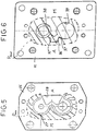
- the configuration of the intermediate plate 26, which is similar to that of the lower cover of the pumps of the prior art in Figures 1 and 2 , allows, during use of the pump, a distribution of output pressure M to be obtained over the outer face 17a of the rear bushing 15b which substantially affects the area P MAX indicated with hatching in Figure 5 .
- This area is greater than the area of the inner face 17b of the rear bushing 15b which is subjected to the output pressure, as long as the force differential owing to the pressure provides for the production of an axial load on the rear bushing 15b directed towards the gears 13, 14, as indicated by arrow S' in Figure 3 .
- the inner face of the front cover 11 unlike the pumps of known type, does not have the omega-like seal, and is instead provided with a large opening 36 which communicates with the intake A of the pump.
- Two limbs 37 which communicate with the openings 38, 39 for housing the shafts 23, 24 of the gears 13, 14 extend from the opening 36.
- This configuration of the face of the front cover 11 ensures that the outer face 17a of the front bushing 15a is subjected only to the intake pressure, which affects, by way of indication, the hatched area, which is denoted P MIN in Figure 6 .
- the pressure differential acts on the front bushing 15a in a manner counter to that seen previously for the rear bushing 15b, as long as during use of the pump, the front bushing 15a, and in particular the two pieces 22a, 22b thereof, are urged firmly against the face of the front cover 11, as indicated by arrow S" in Figure 3 .
- the check pins 29, 30 have different diameters in order to apply different axial loads to the two gears 13, 14. This is because, in the example of the Figure, the driving gear 13 and driven gear 14 are of a helical type and therefore, during operation, produce per se axial loads whose direction is counter to and in accordance with the direction of the axial load applied by the check pins 29, 30. Naturally, in the case of gears having straight teeth which do not produce per se axial loads, the check pins 29, 30 can have substantially corresponding diameters so as to apply an axial load of equal intensity to both of the gears.
Landscapes
- Engineering & Computer Science (AREA)
- Mechanical Engineering (AREA)
- General Engineering & Computer Science (AREA)
- Rotary Pumps (AREA)
Claims (9)
- Verdränger-Rotations-Pumpe umfassend ein Paar ineinander greifender Zahnräder (13, 14) oder Rotoren, bestehend aus einem Triebwerk und einem getriebenen Rad, die in einer Hülle (10) mit einer Ausstoßöffnung und einer Einlassöffnung für ein Fluid enthalten sind, wobei die Zahnräder (13, 14) Wellen (23, 24) umfassen, die durch Laufbuchsen (15a, 15b) mit zwei Flächen (17a, 17b) getragen sind, die im Gebrauch Drücken ausgesetzt sind, die eine Axiallast (S', S") auf die Laufbuchse selber zustande bringen, wobei die Resultierende der Axiallasten (S',S") auf die zwei Laufbuchsen eine vorherbestimmte Richtung aufweist, um die Laufbuchsen (15a, 15b) und die Zahnräder (13, 14) als Ganzes in dichte Widerlagerung mit einer vorherbestimmten Referenzebene (VI-VI) zu bewegen, dadurch gekennzeichnet, dass das Paar ineinander greifender Zahnräder (13, 14) oder Rotoren von dem Typus mit spiralförmigen Zähnen ist und dass Mittel in der Pumpe bereitgestellt sind, so dass das Ausüben von Druck auf die Laufbuchsen (15a, 15b) im Gebrauch Axiallasten (S', S") auf diese Laufbuchsen (15a, 15b) bereitstellt, die immer in die gleiche Richtung wirken wie gegenseitig in Richtung zur Referenzebene (VI-VI), wobei die äußere Fläche (17a) einer (15a) der zwei Laufbuchsen in Richtung zu der Referenzebene (VI-VI) gerichtet ist und nur durch den Einlassdruck (Pmin) beeinflusst ist und ein Abschnitt (PMax) der äußeren Fläche (17a) der anderen (15b) der zwei Laufbuchsen durch den Ausstoß-Druck (M) beeinflusst wird, wobei der Abschnitt (PMax) von dem bleibenden Abschnitt der äußeren Fläche (17a) getrennt ist, der durch den Einlassdruck (A) von einer trennenden Abdichtung (16) beeinflusst wird, die mit einer in Richtung zu der äußeren Fläche (17a) der Laufbuchse (15b) gerichteten Platte (26) in solch einer Weise verbunden ist, dass die Resultierende der Drücke auf die äußere Fläche (17a) der Laufbuchse (15b) konstant größer als die Resultierende der auf die innere Fläche wirkenden Drücke (17b) ist, und dass sie ein System zum Kompensieren der Lasten aufweist, beinhaltend Axiallast-Mittel (29, 30), die auf das selbe Ende jeder Welle (23, 24) der Zahnräder (13, 14) wirken, wobei die Axiallastmittel (29, 30) im Gebrauch eine Axiallast (S''') auf die Zahnräder (13, 14) bewirken, die gegenüber den Axialkräften vorherrscht, welche durch das Ineinandergreifen und das Aufweisen der selben Richtung wie die Resultierende der Axiallasten (S', S") auf die Laufbuchsen (15a, 15b) hergestellt sind.
- Verdränger-Pumpe nach Anspruch 1, dadurch gekennzeichnet, dass die Axiallastmittel Kontrollstifte oder Ausgleichkolben (29, 30) umfassen, die für axiales Gleiten in einer eng anliegenden Weise in entsprechenden Gehäusen (31, 32) befestigt sind, die in einer an einer der zwei Abdeckungen (11, 12) der Hülle (10) der Pumpe fixierten Platte (26) bereitgestellt sind.
- Verdränger-Pumpe nach Anspruch 2, dadurch gekennzeichnet, dass die Enden der Kontrollstifte (29, 30) an einer Seite auf die Enden der Wellen (23, 24) der Zahnräder (13, 14) drücken und an der anderen Seite in Richtung zu einer gemeinsamen Kammer (34) gerichtet sind, die in der Abdeckung (12) der Hülle (10) bereitgestellt ist, wobei die gemeinsame Kammer (34) in Kommunikation mit der Ausstoßöffnung der Rotationspumpe steht.
- Verdränger-Pumpe nach Anspruch 1, dadurch gekennzeichnet, dass die Axiallastmittel (29, 30) verschiedene Dimensionen aufweisen, um verschiedene Axiallasten (S''') auf jedes der Zahnräder anzuwenden.
- Verdränger-Pumpe nach den Ansprüchen 2 und 4, dadurch gekennzeichnet, dass die Kontrollstifte verschiedene Durchmesser aufweisen.
- Verdränger-Pumpe nach einem der vorhergehenden Ansprüche, dadurch gekennzeichnet, dass mindestens eine Laufbuchse (15a, 15b) mindestens zwei separate Stücke (22a, 22b) umfasst, wovon jedes dafür beabsichtigt ist, während der Rotation ein Ende einer der zwei Wellen (23, 24) der Zahnräder (13, 14) zu tragen.
- Verdränger-Pumpe nach Anspruch 6, dadurch gekennzeichnet, dass mindestens ein longitudinaler Kanal (25) an den Flanken jedes separaten Stückes (22a, 22b) der mindestens einen Laufbuchse (15a, 15b) bereitgestellt ist und die Verteilung des Ausstoß-Drucks über den Flanken der Laufbuchse (15a, 15b) fördert, um die zwei separaten Stücke (22a, 22b) dicht zusammenzuhalten.
- Verdränger-Pumpe nach Anspruch 1, dadurch gekennzeichnet, dass Vertiefungen oder lokalisierte Kanäle (50) auf einer (17b) der zwei Flächen mindestens einer der zwei Laufbuchsen (15a, 15b) bereitgestellt sind, um die hydrodynamische Schmierung davon zu ermöglichen.
- Verdränger-Pumpe nach Anspruch 8, dadurch gekennzeichnet, dass die Vertiefungen oder Kanäle sich radial über die Fläche (17b) der Laufbuchse erstrecken, wobei der Profilabschnitt jeder Vertiefung leicht konkav in der Richtung orthogonal zu dem Radius ist, wobei ein leicht tieferer Schlitz oder Kanal (51) in einer im Wesentlichen zentralen Zone jeder Vertiefung (50) bereitgestellt ist.
Applications Claiming Priority (2)
| Application Number | Priority Date | Filing Date | Title |
|---|---|---|---|
| ITBO20010540 | 2001-09-07 | ||
| IT2001BO000540A ITBO20010540A1 (it) | 2001-09-07 | 2001-09-07 | Perfezionamenti in una pompa volumetrica rotativa |
Related Child Applications (1)
| Application Number | Title | Priority Date | Filing Date |
|---|---|---|---|
| EP10186253.0 Division-Into | 2010-10-01 |
Publications (4)
| Publication Number | Publication Date |
|---|---|
| EP1291526A2 EP1291526A2 (de) | 2003-03-12 |
| EP1291526A3 EP1291526A3 (de) | 2003-11-12 |
| EP1291526B1 EP1291526B1 (de) | 2014-03-05 |
| EP1291526B2 true EP1291526B2 (de) | 2020-03-18 |
Family
ID=11439585
Family Applications (1)
| Application Number | Title | Priority Date | Filing Date |
|---|---|---|---|
| EP02020146.3A Expired - Lifetime EP1291526B2 (de) | 2001-09-07 | 2002-09-09 | Zahnradförderpumpe |
Country Status (2)
| Country | Link |
|---|---|
| EP (1) | EP1291526B2 (de) |
| IT (1) | ITBO20010540A1 (de) |
Families Citing this family (12)
| Publication number | Priority date | Publication date | Assignee | Title |
|---|---|---|---|---|
| EP2063126A3 (de) * | 2007-11-22 | 2014-03-12 | Robert Bosch GmbH | Hydraulische Zahnradmschine und Verfahren zum Abdichten einer hydraulischen Zahnradmaschine |
| DE102009012854A1 (de) | 2009-03-12 | 2010-09-16 | Robert Bosch Gmbh | Hydraulische Zahnradmaschine |
| DE102009012856A1 (de) | 2009-03-12 | 2010-09-16 | Robert Bosch Gmbh | Hydraulische Zahnradmaschine |
| DE102009012853A1 (de) | 2009-03-12 | 2010-09-16 | Robert Bosch Gmbh | Hydraulische Zahnradmaschine |
| DE102009012916A1 (de) | 2009-03-12 | 2010-09-16 | Robert Bosch Gmbh | Hydraulische Zahnradmaschine |
| CN101586561B (zh) * | 2009-05-22 | 2011-12-28 | 王良仁 | 高压齿轮油泵 |
| DE102010005900A1 (de) | 2010-01-27 | 2011-07-28 | Robert Bosch GmbH, 70469 | Hydraulische Zahnradmaschine |
| JP6119748B2 (ja) * | 2012-06-11 | 2017-04-26 | 株式会社島津製作所 | 歯車ポンプ又はモータ |
| JP5950020B2 (ja) * | 2013-03-12 | 2016-07-13 | 株式会社島津製作所 | 歯車ポンプ又はモータ |
| JP5761283B2 (ja) * | 2013-09-18 | 2015-08-12 | ダイキン工業株式会社 | ギヤポンプまたはギヤモータ |
| DE112014005509A5 (de) * | 2013-12-03 | 2016-09-29 | Oerlikon Textile Gmbh & Co. Kg | Zahnradpumpe |
| JP2021042730A (ja) | 2019-09-12 | 2021-03-18 | 株式会社島津製作所 | 歯車ポンプ又は歯車モータ |
Family Cites Families (10)
| Publication number | Priority date | Publication date | Assignee | Title |
|---|---|---|---|---|
| US2855855A (en) * | 1949-06-30 | 1958-10-14 | Thompson Prod Inc | High pressure pump |
| US2756684A (en) * | 1954-11-12 | 1956-07-31 | Sier Bath Gear And Pump Co Inc | Rotary gear-type pump |
| US2891483A (en) * | 1956-04-13 | 1959-06-23 | Thompson Ramo Wooldridge Inc | Movable bushing for pressure loaded gear pumps |
| US2981200A (en) | 1956-10-05 | 1961-04-25 | Parker Appliance Co | Gear pump structure |
| FR1197750A (fr) | 1958-01-06 | 1959-12-02 | Pompe à engrenage exempte de poussée axiale | |
| GB880539A (en) * | 1959-04-15 | 1961-10-25 | Clark Equipment Co | Pressure loaded gear pump |
| GB908687A (en) | 1960-03-01 | 1962-10-24 | Bosch Gmbh Robert | Improvements in and relating to hydraulic machines operable as rotary pumps or motors |
| FR1343908A (fr) * | 1962-11-22 | 1963-11-22 | Clark Equipment Co | Pompe ou moteur |
| GB1181224A (en) | 1966-06-20 | 1970-02-11 | Dowty Hydraulic Units Ltd | Gearing and Lubricating Means Therefor |
| US5641281A (en) * | 1995-11-20 | 1997-06-24 | Lci Corporation | Lubricating means for a gear pump |
-
2001
- 2001-09-07 IT IT2001BO000540A patent/ITBO20010540A1/it unknown
-
2002
- 2002-09-09 EP EP02020146.3A patent/EP1291526B2/de not_active Expired - Lifetime
Also Published As
| Publication number | Publication date |
|---|---|
| EP1291526A2 (de) | 2003-03-12 |
| ITBO20010540A0 (it) | 2001-09-07 |
| EP1291526B1 (de) | 2014-03-05 |
| ITBO20010540A1 (it) | 2003-03-07 |
| EP1291526A3 (de) | 2003-11-12 |
Similar Documents
| Publication | Publication Date | Title |
|---|---|---|
| EP1291526B2 (de) | Zahnradförderpumpe | |
| US8979518B2 (en) | Hydraulic toothed wheel machine | |
| US4472123A (en) | Internal gear machine with segmented filler members | |
| EP0749532B1 (de) | Lager für zahnradpumpe | |
| US6887055B2 (en) | Positive-displacement rotary pump | |
| US4361419A (en) | Gerotor liquid pump mounted on a support bushing | |
| US6659748B1 (en) | Axial compensation in an inner geared pump for a closed circuit | |
| EP1531269B1 (de) | Zahnradpumpe oder -motor | |
| EP1132618B1 (de) | Drehkolben-Verdrängungspumpe mit Schraubenrotoren | |
| US3473476A (en) | Gear pump seal | |
| EP0302728B1 (de) | Drehende Ventilplatte | |
| US4704096A (en) | Crowned splines and defination of root radius therefor | |
| EP0394821A2 (de) | Verteilerventil für eine innenachsige Kreiskolbenmaschine | |
| EP0656098B1 (de) | Kompaktgerotorpumpe | |
| US5240393A (en) | Hydraulic machine of the gear type | |
| EP0309130B1 (de) | Innenzahnradmaschine | |
| US3966367A (en) | Hydraulic motor or pump with movable wedge | |
| FI98949C (fi) | Pumppu | |
| CA1146808A (en) | Reversible gear pump or motor and diverter plates therefor | |
| US20040265147A1 (en) | Flanged gear pump | |
| US20020076345A1 (en) | Hydraulic pump | |
| EP0701661B1 (de) | Zahnradpumpe mit regelbarer klemmkraft | |
| RU2099588C1 (ru) | Зубчатолопастная гидромашина | |
| GB2102888A (en) | Rotary positive-displacement pumps | |
| EP0819218B1 (de) | Hydraulische verdrängermaschinen |
Legal Events
| Date | Code | Title | Description |
|---|---|---|---|
| PUAI | Public reference made under article 153(3) epc to a published international application that has entered the european phase |
Free format text: ORIGINAL CODE: 0009012 |
|
| AK | Designated contracting states |
Kind code of ref document: A2 Designated state(s): AT BE BG CH CY CZ DE DK EE ES FI FR GB GR IE IT LI LU MC NL PT SE SK TR Designated state(s): AT BE BG CH CY CZ DE DK EE ES FI FR GB GR IE IT LI LU MC NL PT SE SK TR |
|
| AX | Request for extension of the european patent |
Extension state: AL LT LV MK RO SI |
|
| PUAL | Search report despatched |
Free format text: ORIGINAL CODE: 0009013 |
|
| AK | Designated contracting states |
Kind code of ref document: A3 Designated state(s): AT BE BG CH CY CZ DE DK EE ES FI FR GB GR IE IT LI LU MC NL PT SE SK TR |
|
| AX | Request for extension of the european patent |
Extension state: AL LT LV MK RO SI |
|
| 17P | Request for examination filed |
Effective date: 20040428 |
|
| AKX | Designation fees paid |
Designated state(s): AT BE BG CH CY CZ DE DK EE ES FI FR GB GR IE IT LI LU MC NL PT SE SK TR |
|
| 17Q | First examination report despatched |
Effective date: 20040706 |
|
| GRAP | Despatch of communication of intention to grant a patent |
Free format text: ORIGINAL CODE: EPIDOSNIGR1 |
|
| INTG | Intention to grant announced |
Effective date: 20130619 |
|
| GRAS | Grant fee paid |
Free format text: ORIGINAL CODE: EPIDOSNIGR3 |
|
| GRAA | (expected) grant |
Free format text: ORIGINAL CODE: 0009210 |
|
| AK | Designated contracting states |
Kind code of ref document: B1 Designated state(s): AT BE BG CH CY CZ DE DK EE ES FI FR GB GR IE IT LI LU MC NL PT SE SK TR |
|
| REG | Reference to a national code |
Ref country code: GB Ref legal event code: FG4D |
|
| REG | Reference to a national code |
Ref country code: CH Ref legal event code: EP |
|
| REG | Reference to a national code |
Ref country code: AT Ref legal event code: REF Ref document number: 655067 Country of ref document: AT Kind code of ref document: T Effective date: 20140315 |
|
| REG | Reference to a national code |
Ref country code: IE Ref legal event code: FG4D |
|
| REG | Reference to a national code |
Ref country code: DE Ref legal event code: R096 Ref document number: 60246037 Country of ref document: DE Effective date: 20140417 |
|
| REG | Reference to a national code |
Ref country code: AT Ref legal event code: MK05 Ref document number: 655067 Country of ref document: AT Kind code of ref document: T Effective date: 20140305 |
|
| REG | Reference to a national code |
Ref country code: NL Ref legal event code: VDEP Effective date: 20140305 |
|
| PG25 | Lapsed in a contracting state [announced via postgrant information from national office to epo] |
Ref country code: SE Free format text: LAPSE BECAUSE OF FAILURE TO SUBMIT A TRANSLATION OF THE DESCRIPTION OR TO PAY THE FEE WITHIN THE PRESCRIBED TIME-LIMIT Effective date: 20140305 Ref country code: CY Free format text: LAPSE BECAUSE OF FAILURE TO SUBMIT A TRANSLATION OF THE DESCRIPTION OR TO PAY THE FEE WITHIN THE PRESCRIBED TIME-LIMIT Effective date: 20140305 Ref country code: FI Free format text: LAPSE BECAUSE OF FAILURE TO SUBMIT A TRANSLATION OF THE DESCRIPTION OR TO PAY THE FEE WITHIN THE PRESCRIBED TIME-LIMIT Effective date: 20140305 Ref country code: AT Free format text: LAPSE BECAUSE OF FAILURE TO SUBMIT A TRANSLATION OF THE DESCRIPTION OR TO PAY THE FEE WITHIN THE PRESCRIBED TIME-LIMIT Effective date: 20140305 |
|
| PG25 | Lapsed in a contracting state [announced via postgrant information from national office to epo] |
Ref country code: NL Free format text: LAPSE BECAUSE OF FAILURE TO SUBMIT A TRANSLATION OF THE DESCRIPTION OR TO PAY THE FEE WITHIN THE PRESCRIBED TIME-LIMIT Effective date: 20140305 Ref country code: CZ Free format text: LAPSE BECAUSE OF FAILURE TO SUBMIT A TRANSLATION OF THE DESCRIPTION OR TO PAY THE FEE WITHIN THE PRESCRIBED TIME-LIMIT Effective date: 20140305 Ref country code: EE Free format text: LAPSE BECAUSE OF FAILURE TO SUBMIT A TRANSLATION OF THE DESCRIPTION OR TO PAY THE FEE WITHIN THE PRESCRIBED TIME-LIMIT Effective date: 20140305 Ref country code: BG Free format text: LAPSE BECAUSE OF FAILURE TO SUBMIT A TRANSLATION OF THE DESCRIPTION OR TO PAY THE FEE WITHIN THE PRESCRIBED TIME-LIMIT Effective date: 20140605 Ref country code: BE Free format text: LAPSE BECAUSE OF FAILURE TO SUBMIT A TRANSLATION OF THE DESCRIPTION OR TO PAY THE FEE WITHIN THE PRESCRIBED TIME-LIMIT Effective date: 20140305 |
|
| PG25 | Lapsed in a contracting state [announced via postgrant information from national office to epo] |
Ref country code: SK Free format text: LAPSE BECAUSE OF FAILURE TO SUBMIT A TRANSLATION OF THE DESCRIPTION OR TO PAY THE FEE WITHIN THE PRESCRIBED TIME-LIMIT Effective date: 20140305 Ref country code: ES Free format text: LAPSE BECAUSE OF FAILURE TO SUBMIT A TRANSLATION OF THE DESCRIPTION OR TO PAY THE FEE WITHIN THE PRESCRIBED TIME-LIMIT Effective date: 20140305 |
|
| REG | Reference to a national code |
Ref country code: DE Ref legal event code: R026 Ref document number: 60246037 Country of ref document: DE |
|
| PLBI | Opposition filed |
Free format text: ORIGINAL CODE: 0009260 |
|
| PLBI | Opposition filed |
Free format text: ORIGINAL CODE: 0009260 |
|
| PG25 | Lapsed in a contracting state [announced via postgrant information from national office to epo] |
Ref country code: PT Free format text: LAPSE BECAUSE OF FAILURE TO SUBMIT A TRANSLATION OF THE DESCRIPTION OR TO PAY THE FEE WITHIN THE PRESCRIBED TIME-LIMIT Effective date: 20140707 |
|
| 26 | Opposition filed |
Opponent name: MARZOCCHI POMPE S.P.A. Effective date: 20141202 |
|
| 26 | Opposition filed |
Opponent name: BOSCH REXROTH AG Effective date: 20141205 |
|
| PLAX | Notice of opposition and request to file observation + time limit sent |
Free format text: ORIGINAL CODE: EPIDOSNOBS2 |
|
| PG25 | Lapsed in a contracting state [announced via postgrant information from national office to epo] |
Ref country code: DK Free format text: LAPSE BECAUSE OF FAILURE TO SUBMIT A TRANSLATION OF THE DESCRIPTION OR TO PAY THE FEE WITHIN THE PRESCRIBED TIME-LIMIT Effective date: 20140305 |
|
| PGFP | Annual fee paid to national office [announced via postgrant information from national office to epo] |
Ref country code: FR Payment date: 20140922 Year of fee payment: 13 |
|
| REG | Reference to a national code |
Ref country code: DE Ref legal event code: R026 Ref document number: 60246037 Country of ref document: DE Effective date: 20141202 |
|
| PLBP | Opposition withdrawn |
Free format text: ORIGINAL CODE: 0009264 |
|
| PG25 | Lapsed in a contracting state [announced via postgrant information from national office to epo] |
Ref country code: MC Free format text: LAPSE BECAUSE OF FAILURE TO SUBMIT A TRANSLATION OF THE DESCRIPTION OR TO PAY THE FEE WITHIN THE PRESCRIBED TIME-LIMIT Effective date: 20140305 Ref country code: LU Free format text: LAPSE BECAUSE OF FAILURE TO SUBMIT A TRANSLATION OF THE DESCRIPTION OR TO PAY THE FEE WITHIN THE PRESCRIBED TIME-LIMIT Effective date: 20140909 |
|
| REG | Reference to a national code |
Ref country code: CH Ref legal event code: PL |
|
| PLBB | Reply of patent proprietor to notice(s) of opposition received |
Free format text: ORIGINAL CODE: EPIDOSNOBS3 |
|
| GBPC | Gb: european patent ceased through non-payment of renewal fee |
Effective date: 20140909 |
|
| REG | Reference to a national code |
Ref country code: IE Ref legal event code: MM4A |
|
| PG25 | Lapsed in a contracting state [announced via postgrant information from national office to epo] |
Ref country code: GB Free format text: LAPSE BECAUSE OF NON-PAYMENT OF DUE FEES Effective date: 20140909 Ref country code: CH Free format text: LAPSE BECAUSE OF NON-PAYMENT OF DUE FEES Effective date: 20140930 Ref country code: LI Free format text: LAPSE BECAUSE OF NON-PAYMENT OF DUE FEES Effective date: 20140930 |
|
| PG25 | Lapsed in a contracting state [announced via postgrant information from national office to epo] |
Ref country code: IE Free format text: LAPSE BECAUSE OF NON-PAYMENT OF DUE FEES Effective date: 20140909 |
|
| PLAB | Opposition data, opponent's data or that of the opponent's representative modified |
Free format text: ORIGINAL CODE: 0009299OPPO |
|
| APBM | Appeal reference recorded |
Free format text: ORIGINAL CODE: EPIDOSNREFNO |
|
| APBP | Date of receipt of notice of appeal recorded |
Free format text: ORIGINAL CODE: EPIDOSNNOA2O |
|
| PG25 | Lapsed in a contracting state [announced via postgrant information from national office to epo] |
Ref country code: GR Free format text: LAPSE BECAUSE OF FAILURE TO SUBMIT A TRANSLATION OF THE DESCRIPTION OR TO PAY THE FEE WITHIN THE PRESCRIBED TIME-LIMIT Effective date: 20140606 |
|
| APAH | Appeal reference modified |
Free format text: ORIGINAL CODE: EPIDOSCREFNO |
|
| REG | Reference to a national code |
Ref country code: FR Ref legal event code: ST Effective date: 20160531 |
|
| R26 | Opposition filed (corrected) |
Opponent name: BOSCH REXROTH AG Effective date: 20141205 |
|
| RAP2 | Party data changed (patent owner data changed or rights of a patent transferred) |
Owner name: SETTIMA MECCANICA SRL - SOCIETA A SOCIO UNICO |
|
| RIN2 | Information on inventor provided after grant (corrected) |
Inventor name: SETTIMA MECCANICA SRL - SOCIETA A SOCIO UNICO |
|
| PG25 | Lapsed in a contracting state [announced via postgrant information from national office to epo] |
Ref country code: TR Free format text: LAPSE BECAUSE OF FAILURE TO SUBMIT A TRANSLATION OF THE DESCRIPTION OR TO PAY THE FEE WITHIN THE PRESCRIBED TIME-LIMIT Effective date: 20140305 |
|
| APBQ | Date of receipt of statement of grounds of appeal recorded |
Free format text: ORIGINAL CODE: EPIDOSNNOA3O |
|
| PG25 | Lapsed in a contracting state [announced via postgrant information from national office to epo] |
Ref country code: FR Free format text: LAPSE BECAUSE OF NON-PAYMENT OF DUE FEES Effective date: 20150930 |
|
| RIN2 | Information on inventor provided after grant (corrected) |
Inventor name: MORSELLI MARIO ANTONIO |
|
| RAP2 | Party data changed (patent owner data changed or rights of a patent transferred) |
Owner name: SETTIMA MECCANICA SRL - SOCIETA A SOCIO UNICO |
|
| APBU | Appeal procedure closed |
Free format text: ORIGINAL CODE: EPIDOSNNOA9O |
|
| PUAH | Patent maintained in amended form |
Free format text: ORIGINAL CODE: 0009272 |
|
| STAA | Information on the status of an ep patent application or granted ep patent |
Free format text: STATUS: PATENT MAINTAINED AS AMENDED |
|
| 27A | Patent maintained in amended form |
Effective date: 20200318 |
|
| AK | Designated contracting states |
Kind code of ref document: B2 Designated state(s): AT BE BG CH CY CZ DE DK EE ES FI FR GB GR IE IT LI LU MC NL PT SE SK TR |
|
| REG | Reference to a national code |
Ref country code: DE Ref legal event code: R102 Ref document number: 60246037 Country of ref document: DE |
|
| PGFP | Annual fee paid to national office [announced via postgrant information from national office to epo] |
Ref country code: IT Payment date: 20210824 Year of fee payment: 20 |
|
| PGFP | Annual fee paid to national office [announced via postgrant information from national office to epo] |
Ref country code: DE Payment date: 20210818 Year of fee payment: 20 |
|
| REG | Reference to a national code |
Ref country code: DE Ref legal event code: R071 Ref document number: 60246037 Country of ref document: DE |