EP1291130A2 - Bearbeitungszentrum für runde Werkstücke - Google Patents
Bearbeitungszentrum für runde Werkstücke Download PDFInfo
- Publication number
- EP1291130A2 EP1291130A2 EP02017560A EP02017560A EP1291130A2 EP 1291130 A2 EP1291130 A2 EP 1291130A2 EP 02017560 A EP02017560 A EP 02017560A EP 02017560 A EP02017560 A EP 02017560A EP 1291130 A2 EP1291130 A2 EP 1291130A2
- Authority
- EP
- European Patent Office
- Prior art keywords
- machining center
- bed
- center according
- machining
- machine bed
- Prior art date
- Legal status (The legal status is an assumption and is not a legal conclusion. Google has not performed a legal analysis and makes no representation as to the accuracy of the status listed.)
- Withdrawn
Links
Images

Classifications
-
- B—PERFORMING OPERATIONS; TRANSPORTING
- B23—MACHINE TOOLS; METAL-WORKING NOT OTHERWISE PROVIDED FOR
- B23Q—DETAILS, COMPONENTS, OR ACCESSORIES FOR MACHINE TOOLS, e.g. ARRANGEMENTS FOR COPYING OR CONTROLLING; MACHINE TOOLS IN GENERAL CHARACTERISED BY THE CONSTRUCTION OF PARTICULAR DETAILS OR COMPONENTS; COMBINATIONS OR ASSOCIATIONS OF METAL-WORKING MACHINES, NOT DIRECTED TO A PARTICULAR RESULT
- B23Q1/00—Members which are comprised in the general build-up of a form of machine, particularly relatively large fixed members
- B23Q1/01—Frames, beds, pillars or like members; Arrangement of ways
- B23Q1/015—Frames, beds, pillars
-
- B—PERFORMING OPERATIONS; TRANSPORTING
- B23—MACHINE TOOLS; METAL-WORKING NOT OTHERWISE PROVIDED FOR
- B23Q—DETAILS, COMPONENTS, OR ACCESSORIES FOR MACHINE TOOLS, e.g. ARRANGEMENTS FOR COPYING OR CONTROLLING; MACHINE TOOLS IN GENERAL CHARACTERISED BY THE CONSTRUCTION OF PARTICULAR DETAILS OR COMPONENTS; COMBINATIONS OR ASSOCIATIONS OF METAL-WORKING MACHINES, NOT DIRECTED TO A PARTICULAR RESULT
- B23Q1/00—Members which are comprised in the general build-up of a form of machine, particularly relatively large fixed members
- B23Q1/25—Movable or adjustable work or tool supports
- B23Q1/44—Movable or adjustable work or tool supports using particular mechanisms
- B23Q1/56—Movable or adjustable work or tool supports using particular mechanisms with sliding pairs only, the sliding pairs being the first two elements of the mechanism
- B23Q1/60—Movable or adjustable work or tool supports using particular mechanisms with sliding pairs only, the sliding pairs being the first two elements of the mechanism two sliding pairs only, the sliding pairs being the first two elements of the mechanism
- B23Q1/62—Movable or adjustable work or tool supports using particular mechanisms with sliding pairs only, the sliding pairs being the first two elements of the mechanism two sliding pairs only, the sliding pairs being the first two elements of the mechanism with perpendicular axes, e.g. cross-slides
- B23Q1/621—Movable or adjustable work or tool supports using particular mechanisms with sliding pairs only, the sliding pairs being the first two elements of the mechanism two sliding pairs only, the sliding pairs being the first two elements of the mechanism with perpendicular axes, e.g. cross-slides a single sliding pair followed perpendicularly by a single sliding pair
- B23Q1/626—Movable or adjustable work or tool supports using particular mechanisms with sliding pairs only, the sliding pairs being the first two elements of the mechanism two sliding pairs only, the sliding pairs being the first two elements of the mechanism with perpendicular axes, e.g. cross-slides a single sliding pair followed perpendicularly by a single sliding pair followed perpendicularly by a single sliding pair
-
- B—PERFORMING OPERATIONS; TRANSPORTING
- B23—MACHINE TOOLS; METAL-WORKING NOT OTHERWISE PROVIDED FOR
- B23Q—DETAILS, COMPONENTS, OR ACCESSORIES FOR MACHINE TOOLS, e.g. ARRANGEMENTS FOR COPYING OR CONTROLLING; MACHINE TOOLS IN GENERAL CHARACTERISED BY THE CONSTRUCTION OF PARTICULAR DETAILS OR COMPONENTS; COMBINATIONS OR ASSOCIATIONS OF METAL-WORKING MACHINES, NOT DIRECTED TO A PARTICULAR RESULT
- B23Q3/00—Devices holding, supporting, or positioning work or tools, of a kind normally removable from the machine
- B23Q3/155—Arrangements for automatic insertion or removal of tools, e.g. combined with manual handling
-
- Y—GENERAL TAGGING OF NEW TECHNOLOGICAL DEVELOPMENTS; GENERAL TAGGING OF CROSS-SECTIONAL TECHNOLOGIES SPANNING OVER SEVERAL SECTIONS OF THE IPC; TECHNICAL SUBJECTS COVERED BY FORMER USPC CROSS-REFERENCE ART COLLECTIONS [XRACs] AND DIGESTS
- Y10—TECHNICAL SUBJECTS COVERED BY FORMER USPC
- Y10T—TECHNICAL SUBJECTS COVERED BY FORMER US CLASSIFICATION
- Y10T29/00—Metal working
- Y10T29/51—Plural diverse manufacturing apparatus including means for metal shaping or assembling
- Y10T29/5104—Type of machine
- Y10T29/5109—Lathe
- Y10T29/5114—Lathe and tool
-
- Y—GENERAL TAGGING OF NEW TECHNOLOGICAL DEVELOPMENTS; GENERAL TAGGING OF CROSS-SECTIONAL TECHNOLOGIES SPANNING OVER SEVERAL SECTIONS OF THE IPC; TECHNICAL SUBJECTS COVERED BY FORMER USPC CROSS-REFERENCE ART COLLECTIONS [XRACs] AND DIGESTS
- Y10—TECHNICAL SUBJECTS COVERED BY FORMER USPC
- Y10T—TECHNICAL SUBJECTS COVERED BY FORMER US CLASSIFICATION
- Y10T483/00—Tool changing
- Y10T483/17—Tool changing including machine tool or component
- Y10T483/1702—Rotating work machine tool [e.g., screw machine, lathe, etc.]
- Y10T483/1705—Tool support comprises rotary spindle
-
- Y—GENERAL TAGGING OF NEW TECHNOLOGICAL DEVELOPMENTS; GENERAL TAGGING OF CROSS-SECTIONAL TECHNOLOGIES SPANNING OVER SEVERAL SECTIONS OF THE IPC; TECHNICAL SUBJECTS COVERED BY FORMER USPC CROSS-REFERENCE ART COLLECTIONS [XRACs] AND DIGESTS
- Y10—TECHNICAL SUBJECTS COVERED BY FORMER USPC
- Y10T—TECHNICAL SUBJECTS COVERED BY FORMER US CLASSIFICATION
- Y10T483/00—Tool changing
- Y10T483/17—Tool changing including machine tool or component
- Y10T483/1733—Rotary spindle machine tool [e.g., milling machine, boring, machine, grinding machine, etc.]
- Y10T483/1748—Tool changer between spindle and matrix
Definitions
- the invention relates to a machining center for round workpieces according to the Preamble of claim 1.
- the object of the invention is to provide a machining center of the type mentioned create a complete machining of round workpieces in one clamping allows.
- the machining center according to the invention is characterized by a broad Range of applications with high static and dynamic rigidity.
- Machining technologies such as milling, drilling, rotary milling, 5/6 axis machining, Thread milling, deep drilling, gear cutting and especially grinding with high Accuracy can be carried out in a workpiece clamping. This will make one Complete machining of larger and more complex shaped round and asymmetrical Workpieces possible without reclamping.
- the easy interchangeability of the different processing units ensures high productivity and optimal economy.
- the modular structure also enables one subsequent expansion by adapting the corresponding processing units. This means that one originally intended for other machining tasks Machine can be expanded with new technologies.
- the machine is an automatic chip conveyor in the Integrated machine bed.
- the carrier holding the different processing units is in one particularly expedient execution in a kind of quill-shaped stamp. It is located in an inclined headstock unit, which in turn is on a sled-shaped, movable carrier unit can be moved on the bed can.
- the punch is oblique in the upper headstock in the direction of the tool top down, NC controlled, movable. This will be an optimal one Guaranteed freedom of work space on the processing module and the risk of collision reduced.
- the quill-like stamp is a motor-driven one Drive spindle arranged. This allows the different Machining units are driven by a central unit, provided they do not own drive (motor spindles).
- the machine bed is in a particularly solid and dimensionally stable design Step bed with a front bed section and a raised rear bed section. This means that even large and heavy components can be machined with high accuracy to be edited.
- the main spindle is driven by one or two parallel drive motors. This is an optimal adjustment of the Drive to the different performance requirements possible.
- the drive is as Rotary, positioning and round milling drive.
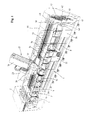
- the machining center for round shown schematically in Figures 1 and 2 Workpieces contain a machine bed 1 and a headstock 2 in which one horizontal workpiece drive spindle 3 with a chuck front workpiece clamping device 4 is arranged rotatably.
- the drive of the Workpiece drive spindle 3 is carried out by one or two parallel drive motors 5 and 6 via a switchable two-stage planetary gear 7, which for a high Operational safety and optimal smoothness ensures.
- the drive can be optimally adapted to the machine.
- the Drive is designed such that it is used both as a rotary drive and as a positioning and Round milling drive can be used.
- the machine bed 1 is a one-piece step bed with a front bed section 8 and a raised rear bed section 9. Between the front bed part 8 and the rear bed part 9 is 1 in the machine bed a chip conveyor 10 for automatic removal of those arising during processing Chips integrated.
- the front bed part 8 contains two parallel guideways 11, which a tailstock 12 guided motor adjustable in a horizontal longitudinal axis is.
- a tailstock housing is adjustable in the longitudinal direction via a motor 13 Quill 14 arranged. In the quill there is an axis with Rotates workpiece speed and in which a tailstock tip 15 is inserted. Between the chuck 4 and the tailstock tip 15 becomes a workpiece 16 to be machined curious; excited.
- the motorized adjustment of the tailstock 12 and the quill 14 guarantee a quick and safe workpiece pick-up. Due to the quill design is a sensitive adjustment of the tailstock to the workpiece possible, which means less axial stiff workpieces can be clamped precisely. In addition, there is a in the quill Integrated spring package, which compensates for the length of the workpiece by e.g. Temperature-related changes in length allowed.
- a large number of different processing units 18 to 24, shown in FIG. 3 arranged with the help of these processing units, different Machining technologies, such as Turning, milling, rotary milling, drilling, 5/6-axis machining, Thread milling, deep drilling, gear cutting and even grinding performed become.
- the support 17 contains a bed slide 26 which via guides 27 on the top of the rear bed part 9 in a to the longitudinal axis of the Workpiece parallel first linear axis 28 (Z axis) can be moved by motor is arranged.
- first linear axis 28 Z axis
- second linear axis 31 Y axis
- a carrier 32 in the form of a stamp in a third linear axis 33 (X axis) perpendicular to the two linear axes 28 and 31 Can be moved across the workpiece.
- an interface 34 is provided, which not only the secure mounting of the different processing units, but also their optimal supply with different media guaranteed.
- a motor is rotatably driven spindle 35, via which the drive of the Processing units are provided that they do not have their own drive.
- FIG 3 are some examples of processing units with the associated Machining examples shown on a rotating part 16.
- On the left is an as Angular head executed drilling or milling unit 18 shown. With this e.g. the end holes in the rotary part 16 are made.
- a machining unit 19 for performing 5/6 axis machining shown.
- This contains a swivel part, which is an additional Axis of rotation is pivotable and is received in a fork-shaped holder. With This additional axis can also be used for complex paths on curved surfaces getting produced. Together with another axis of rotation about the longitudinal axis of the stamp-shaped support can ultimately at any angle in the room standing surfaces are processed.
- this rotating unit 20 e.g. Longitudinal, plan and Contour turning operations are carried out.
- a Milling unit 21 shown with a side milling cutter With this e.g. the shown Slots are made on the outside of the rotating part 16.
- straight Milling unit 22 and a milling unit 23 provided with a motor spindle are shown.
- the processing units can also be high-speed Include attachment spindles that enable high-speed machining.
- a grinding unit is also shown on the right-hand side the conventional machining centers also carried out grinding operations can be.
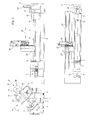
- the processing units are a device for automatic tool change intended.
- This device consists of a tool magazine 37 and a Tool changer 38 for transporting the workpieces between the tool magazine 37 and a processing unit 18 arranged in the carrier 32.
- the tool changer 38 includes a vertical support bracket 39 that extends over upper and lower guide rails 40 or 41 is arranged to be movable transversely to the longitudinal axis of the machine bed 1.
- a carriage 42 is guided so as to be movable in the vertical axis.
- the Carriage 42 carries tool gripper 43, designed as a double gripper, through which Tool clamped in the processing unit 18 against a tool magazine 37 located tool can be replaced.
- the tool magazine 37 is as Shelf magazine executed, the extension of the machine bed 1 at the end of Machining center is space-saving and can be expanded as required. Also the Tool changing device could, however, on the guideways 11 of the front Bed part 8 can be arranged to be movable.
- lunettes can also be arranged on the front bed part 8 for support. Particularly high accuracy can be achieved with NC-controlled steadies, which are adjustable in all axes.
- the steady rests can be used in a basic version Roller steady rest or for certain tasks as hydrodynamic or hydrostatic Bezel with synchronous or individually adjustable supports.
- the work space encapsulation 44 shown schematically in FIG Work area covered in such a way that all support tours outside the Workspace. This can prevent these guides from becoming dirty protected and their wear can be minimized.
Landscapes
- Engineering & Computer Science (AREA)
- Mechanical Engineering (AREA)
- Turning (AREA)
- Automatic Tool Replacement In Machine Tools (AREA)
Abstract
Description
- Figur 1
- eine schematische Gesamtdarstellung eines erfindungsgemäßen Bearbeitungszentrums für runde Werkstücke in einer Perspektive;
- Figur 2
- den Grundaufbau des in Figur 1 gezeigten Bearbeitungszentrums in einer Vorderansicht, Seitenansicht und Draufsicht und
- Figur 3
- verschiedene Bearbeitungseinheiten zur Durchführung unterschiedlicher Bearbeitungstechnologien an einem runden Werkstück.
Claims (15)
- Bearbeitungszentrum für runde Werkstücke mit
einem Maschinenbett (1),
einer in einem seitlichen Spindelstock (2) am Maschinenbett (1) drehbar gelagerten und durch einen Antrieb (5, 6, 7) drehangetriebenen horizontalen Hauptantriebsspindel (3) mit einer Werkstückspannvorrichtung (4),
einem auf dem Maschinenbett (1) angeordneten Reitstock (12) und
einem auf dem Maschinenbett (1) verfahrbar angeordneten Support (17),
dadurch gekennzeichnet, daß der Support (17) einen auf dem Maschinenbett (1) verfahrbaren Bettschlitten (26) und einen an diesem schräg angeordneten oberen Spindelstock (30) mit einem in dessen Längsachse verfahrbaren Träger (32) aufweist, in den austauschbare Bearbeitungseinheiten (18, 19, 20, 21, 22, 23, 24) zur Durchführung unterschiedlicher Bearbeitungstechnologien einsetzbar sind. - Bearbeitungszentrum nach Anspruch 1, dadurch gekennzeichnet, daß der obere Spindelstock (30) an der Seite des nach oben abgeschrägten und in einer ersten Linearachse (28) verfahrbaren Bettschlittens (26) in einer unter einem Winkel zur Horizontalen verlaufenden zweiten Linearachse (31) verfahrbar angeordnet ist.
- Bearbeitungszentrum nach Anspruch 2, dadurch gekennzeichnet, daß der Träger (32) in einer zu der ersten und zweiten Linearachse (28, 31) senkrechten dritten Linearachse (33) motorisch verfahrbar im oberen Spindelstock (30) angeordnet ist.
- Bearbeitungszentrum nach einem der Ansprüche 1 bis 3, dadurch gekennzeichnet, daß in dem Träger (32) eine motorisch drehangetriebene Spindel (35) zum Antrieb der ohne eigenen Antrieb ausgeführten Bearbeitungseinheiten (18, 19, 20, 21, 22, 23, 24) angeordnet ist.
- Bearbeitungszentrum nach einem der Ansprüche 1 bis 4, dadurch gekennzeichnet, daß der Träger (32) in Art eines pinolenförmigen Stempels ausgebildet ist.
- Bearbeitungszentrum nach einem der Ansprüche 1 bis 5, dadurch gekennzeichnet, daß das einteilige Maschinenbett (1) ein Stufenbett mit einem vorderen Bettteil (8) und einem erhöhten hinteren waagrechten Bettteil (9) ist.
- Bearbeitungszentrum nach Anspruch 6, dadurch gekennzeichnet, daß der Bettschlitten (26) auf dem erhöhten hinteren Bettkörper (9) des Maschinenbetts (1) verfahrbar angeordnet ist.
- Bearbeitungszentrum nach einem der Ansprüche 1 bis 7, dadurch gekennzeichnet, daß in das Maschinenbett (1) ein Späneförderer (10) zum automatischen Abtransport der bei der Bearbeitung anfallenden Späne integriert ist.
- Bearbeitungszentrum nach einem der Ansprüche 1 bis 8, dadurch gekennzeichnet, daß der Antrieb (5, 6, 7) der Hauptantriebsspindel (3) als Dreh-, Positionier- und CNC-geregelter Rundfräsantrieb ausgeführt ist.
- Bearbeitungszentrum nach einem der Ansprüche 1 bis 9, dadurch gekennzeichnet, daß der Antrieb (5, 6, 7) der Hauptantriebsspindel (3) ein oder zwei parallele Antriebsmotoren (5, 6) und je Motor ein schaltbares Getriebe (7) enthält.
- Bearbeitungszentrum nach einem der Ansprüche 1 bis 10, dadurch gekennzeichnet, daß die Bearbeitungseinheiten (18, 19, 20, 21, 22, 23, 24) durch Verfahrbewegungen des Supports (17) im Pick-up-Prinzip austauschbar sind.
- Bearbeitungszentrum nach einem der Ansprüche 1 bis 11, dadurch gekennzeichnet, daß am reitstockseitigen Ende des Maschinenbetts (1) ein Magazin (36) zur Speicherung mehrerer Bearbeitungseinheiten (18, 19, 20, 21, 22, 23, 24) angeordnet ist.
- Bearbeitungszentrum nach einem der Ansprüche 1 bis 12, dadurch gekennzeichnet, daß am reitstockseitigen Ende des Maschinenbetts (1) eine Einrichtung (37, 38) zum automatischen Werkzeugwechsel angeordnet ist.
- Bearbeitungszentrum nach Anspruch 13, dadurch gekennzeichnet, daß die Einrichtung zum automatischen Werkzeugwechsel (37, 38) ein Werkzeugmagazin (37) und einem automatischen Werkzeugwechsler (38) enthält.
- Bearbeitungszentrum einem der Ansprüche 1 bis 14, dadurch gekennzeichnet, daß sie eine Arbeitsraumkapselung (44) enthält, durch welche die Führungen, Werkzeugwechsler, Pick-up-Station und Spindelstock vom Arbeitsraum getrennt sind.
Applications Claiming Priority (2)
| Application Number | Priority Date | Filing Date | Title |
|---|---|---|---|
| DE10144679A DE10144679A1 (de) | 2001-09-11 | 2001-09-11 | Bearbeitungszentrum |
| DE10144679 | 2001-09-11 |
Publications (2)
| Publication Number | Publication Date |
|---|---|
| EP1291130A2 true EP1291130A2 (de) | 2003-03-12 |
| EP1291130A3 EP1291130A3 (de) | 2003-07-02 |
Family
ID=7698596
Family Applications (1)
| Application Number | Title | Priority Date | Filing Date |
|---|---|---|---|
| EP02017560A Withdrawn EP1291130A3 (de) | 2001-09-11 | 2002-08-07 | Bearbeitungszentrum für runde Werkstücke |
Country Status (4)
| Country | Link |
|---|---|
| US (1) | US20030069115A1 (de) |
| EP (1) | EP1291130A3 (de) |
| JP (1) | JP2003094205A (de) |
| DE (1) | DE10144679A1 (de) |
Cited By (7)
| Publication number | Priority date | Publication date | Assignee | Title |
|---|---|---|---|---|
| DE102013207125A1 (de) | 2013-04-19 | 2014-10-23 | Heinrich Georg Gmbh Maschinenfabrik | Bearbeitungszentrum, insbesondere Dreh-/Bohr-/Fräs-/Schleifzentrum zur Bearbeitung von Werkstücken |
| CN104647104A (zh) * | 2015-02-13 | 2015-05-27 | 苏州江源精密机械有限公司 | 龙门加工中心的旋转式附件头自动更换头库装置 |
| CN104647105A (zh) * | 2015-02-13 | 2015-05-27 | 苏州江源精密机械有限公司 | 龙门加工中心上附加头自动更换头库装置 |
| EP3456463A1 (de) * | 2017-09-14 | 2019-03-20 | AFW Holding GmbH | Bearbeitungskopf zur mechanischen, insbesondere spanenden, bearbeitung, insbesondere zur aussteuerung, eines werkstücks |
| EP3581327A4 (de) * | 2017-02-07 | 2020-11-04 | Makino Milling Machine Co., Ltd. | Werkzeugmaschine |
| CN114290130A (zh) * | 2021-12-25 | 2022-04-08 | 九众九机器人有限公司 | 一种工件轮廓加工工艺 |
| CN115365835A (zh) * | 2022-09-27 | 2022-11-22 | 南通国盛智能科技集团股份有限公司 | 一种桥式龙门加工中心 |
Families Citing this family (3)
| Publication number | Priority date | Publication date | Assignee | Title |
|---|---|---|---|---|
| DE102006017664A1 (de) * | 2006-04-12 | 2007-10-18 | Volkswagen Ag | Verfahren und Vorrichtung zum Herstellen einer Form für Ur- und Umformwerkzeuge |
| DE102009020023A1 (de) * | 2009-05-05 | 2010-11-11 | Liebherr-Verzahntechnik Gmbh | Verzahnmaschine mit Schnittstelle |
| US9586299B2 (en) * | 2014-12-08 | 2017-03-07 | Jpw Industries Inc. | Non-slip mat for lathe |
Citations (6)
| Publication number | Priority date | Publication date | Assignee | Title |
|---|---|---|---|---|
| EP0239564A2 (de) * | 1986-03-26 | 1987-09-30 | Maschinenfabrik Heid Aktiengesellschaft | Drehmaschine |
| JPS63191530A (ja) * | 1987-01-30 | 1988-08-09 | Yamazaki Mazak Corp | 複合加工工作機械におけるワ−クの加工方法 |
| EP0314824A1 (de) * | 1987-11-03 | 1989-05-10 | Waldrich Siegen Werkzeugmaschinenbau GmbH | Mehrachsen- bzw. Universal-Fräsmaschine |
| US5289622A (en) * | 1991-03-11 | 1994-03-01 | Dainichi Kinzoku Kogyo Kabushiki Kaisha | Carriage structure of NC lathe |
| US5490307A (en) * | 1991-10-19 | 1996-02-13 | Index-Werke Gmbh & Co. Kg Hahn & Tessky | Lathe |
| EP0900627A2 (de) * | 1997-09-04 | 1999-03-10 | Mori Seiki Co., Ltd. | Mehrzweckdrehmaschine |
Family Cites Families (14)
| Publication number | Priority date | Publication date | Assignee | Title |
|---|---|---|---|---|
| BE386933A (de) * | 1931-12-28 | 1900-01-01 | ||
| GB1223565A (en) * | 1967-06-26 | 1971-02-24 | Wickman Mach Tool Sales Ltd | Turning machines |
| CH510488A (de) * | 1969-05-20 | 1971-07-31 | Dubied & Cie Sa E | Drehmaschine |
| US3894808A (en) * | 1971-08-06 | 1975-07-15 | Vincent Zarlengo | Mount adapter for cutting tools and method of operating |
| AT378710B (de) * | 1983-12-01 | 1985-09-25 | Voest Alpine Ag | Drehmaschine |
| DE3410276A1 (de) * | 1984-03-17 | 1984-10-31 | H. Wohlenberg KG - GmbH & Co, 3000 Hannover | Drehmaschine |
| US4701818A (en) * | 1986-02-18 | 1987-10-20 | Magnetic Peripherals Inc. | Means for indexing a rotary arm in small angular steps |
| JPS6374534A (ja) * | 1986-09-12 | 1988-04-05 | Tsugami Corp | 複合加工工作機械 |
| FR2641220B1 (fr) * | 1988-05-25 | 1994-06-03 | Somab Sa | Machine-outil multifonctions permettant des usinages complexes de pieces longues |
| US5111562A (en) * | 1990-11-27 | 1992-05-12 | Versa Tech Engineering | Spindle apparatus for holding a workpiece |
| JPH04269137A (ja) * | 1991-02-20 | 1992-09-25 | Tsugami Corp | 複合加工工作機械 |
| DE4414856C2 (de) * | 1994-04-28 | 1997-03-27 | Max Mueller Werkzeugmaschinen | Drehmaschine mit einem Werkzeugturm zur Aufnahme nicht rotierender und rotierender Werkzeuge |
| US5885199A (en) * | 1996-02-06 | 1999-03-23 | Shao; Wenyuan | Compact machining center for multifunction |
| JP3167644B2 (ja) * | 1997-06-20 | 2001-05-21 | 株式会社森精機製作所 | 複合工作機械の工具主軸固定装置 |
-
2001
- 2001-09-11 DE DE10144679A patent/DE10144679A1/de not_active Withdrawn
-
2002
- 2002-08-07 EP EP02017560A patent/EP1291130A3/de not_active Withdrawn
- 2002-08-29 US US10/233,317 patent/US20030069115A1/en not_active Abandoned
- 2002-09-11 JP JP2002265777A patent/JP2003094205A/ja not_active Withdrawn
Patent Citations (6)
| Publication number | Priority date | Publication date | Assignee | Title |
|---|---|---|---|---|
| EP0239564A2 (de) * | 1986-03-26 | 1987-09-30 | Maschinenfabrik Heid Aktiengesellschaft | Drehmaschine |
| JPS63191530A (ja) * | 1987-01-30 | 1988-08-09 | Yamazaki Mazak Corp | 複合加工工作機械におけるワ−クの加工方法 |
| EP0314824A1 (de) * | 1987-11-03 | 1989-05-10 | Waldrich Siegen Werkzeugmaschinenbau GmbH | Mehrachsen- bzw. Universal-Fräsmaschine |
| US5289622A (en) * | 1991-03-11 | 1994-03-01 | Dainichi Kinzoku Kogyo Kabushiki Kaisha | Carriage structure of NC lathe |
| US5490307A (en) * | 1991-10-19 | 1996-02-13 | Index-Werke Gmbh & Co. Kg Hahn & Tessky | Lathe |
| EP0900627A2 (de) * | 1997-09-04 | 1999-03-10 | Mori Seiki Co., Ltd. | Mehrzweckdrehmaschine |
Non-Patent Citations (1)
| Title |
|---|
| PATENT ABSTRACTS OF JAPAN vol. 012, no. 466 (M-772), 7. Dezember 1988 (1988-12-07) & JP 63 191530 A (YAMAZAKI MAZAK CORP), 9. August 1988 (1988-08-09) * |
Cited By (12)
| Publication number | Priority date | Publication date | Assignee | Title |
|---|---|---|---|---|
| DE102013207125A1 (de) | 2013-04-19 | 2014-10-23 | Heinrich Georg Gmbh Maschinenfabrik | Bearbeitungszentrum, insbesondere Dreh-/Bohr-/Fräs-/Schleifzentrum zur Bearbeitung von Werkstücken |
| WO2014170367A1 (de) | 2013-04-19 | 2014-10-23 | Heinrich Georg Gmbh Maschinenfabrik | Bearbeitungszentrum, insbesondere dreh-/bohr-/fräs-/schleifzentrum zur bearbeitung von werkstücken |
| CN104647104A (zh) * | 2015-02-13 | 2015-05-27 | 苏州江源精密机械有限公司 | 龙门加工中心的旋转式附件头自动更换头库装置 |
| CN104647105A (zh) * | 2015-02-13 | 2015-05-27 | 苏州江源精密机械有限公司 | 龙门加工中心上附加头自动更换头库装置 |
| CN104647105B (zh) * | 2015-02-13 | 2017-10-20 | 苏州江源精密机械有限公司 | 龙门加工中心上附加头自动更换头库装置 |
| EP3581327A4 (de) * | 2017-02-07 | 2020-11-04 | Makino Milling Machine Co., Ltd. | Werkzeugmaschine |
| US11407071B2 (en) | 2017-02-07 | 2022-08-09 | Makino Milling Machine Co., Ltd. | Machine tool |
| EP3456463A1 (de) * | 2017-09-14 | 2019-03-20 | AFW Holding GmbH | Bearbeitungskopf zur mechanischen, insbesondere spanenden, bearbeitung, insbesondere zur aussteuerung, eines werkstücks |
| WO2019052853A1 (de) * | 2017-09-14 | 2019-03-21 | Afw Holding Gmbh | Bearbeitungskopf zur mechanischen, insbesondere spanenden, bearbeitung eines werkstücks |
| US11945068B2 (en) | 2017-09-14 | 2024-04-02 | Afw Holding Gmbh | Machining head for the mechanical, in particular cutting, machining of a workpiece |
| CN114290130A (zh) * | 2021-12-25 | 2022-04-08 | 九众九机器人有限公司 | 一种工件轮廓加工工艺 |
| CN115365835A (zh) * | 2022-09-27 | 2022-11-22 | 南通国盛智能科技集团股份有限公司 | 一种桥式龙门加工中心 |
Also Published As
| Publication number | Publication date |
|---|---|
| DE10144679A1 (de) | 2003-03-27 |
| US20030069115A1 (en) | 2003-04-10 |
| JP2003094205A (ja) | 2003-04-03 |
| EP1291130A3 (de) | 2003-07-02 |
Similar Documents
| Publication | Publication Date | Title |
|---|---|---|
| EP1291122B1 (de) | Fräs- und Bohrbearbeitungszentrum | |
| EP1046461B1 (de) | Universal-Werkzeugmaschine | |
| EP1338376B1 (de) | Fräsmaschine zur Fräs- und Drehbearbeitung von Stangenmaterial | |
| DE3721610C2 (de) | ||
| DE102004061318B4 (de) | Werkzeugmaschine mit Werkzeugwechsler | |
| DE60303672T2 (de) | Werkzeugmaschine | |
| DE3427245A1 (de) | Werkzeugmaschine | |
| DE3420531C2 (de) | Drehautomat | |
| EP1413395A1 (de) | Werkzeugmaschine | |
| EP0995539A2 (de) | Bearbeitungsvorrichtung für Werkstücke | |
| DE2033026B2 (de) | NC-gesteueites Bearbeitungszentrum für durch Drehen von beiden Seiten her sowie durch Fräsen und/oder Bohren zu bearbeitende Werkstücke | |
| DE102006042006B4 (de) | Drehmaschine | |
| DE10034973C2 (de) | Universalwerkzeugmaschine mit im Pick-up Modus wechselbaren Werkstückträger | |
| DE10307977C5 (de) | Verfahren und Vorrichtung zur Bearbeitung von Ausgleichsgehäusen | |
| EP1294530B1 (de) | Werkzeug-maschine zur mindestens 3-achsigen bearbeitung von werkstücken | |
| DE102010051865A1 (de) | Werkzeugmaschine | |
| EP1291130A2 (de) | Bearbeitungszentrum für runde Werkstücke | |
| DE2409773B2 (de) | Kurvenlos programmgesteuerter mehrspindel-drehautomat | |
| EP3784432A1 (de) | Werkzeugmaschine mit einer arbeitspindel auf einer schrägfläche | |
| DE102005027785B4 (de) | Mehrachsige Drehbearbeitungsvorrichtung und Verfahren zum Drehen eines Werkstücks damit | |
| DE3530982A1 (de) | Zweispindlige, numerisch gesteuerte drehmaschine | |
| EP0410044B1 (de) | Drehmaschine mit drei Werkstückspindeln | |
| EP3624988B1 (de) | Werkzeugmaschine | |
| DE3824572C2 (de) | ||
| DE19607883A1 (de) | Vertikal-Drehmaschine |
Legal Events
| Date | Code | Title | Description |
|---|---|---|---|
| PUAI | Public reference made under article 153(3) epc to a published international application that has entered the european phase |
Free format text: ORIGINAL CODE: 0009012 |
|
| AK | Designated contracting states |
Kind code of ref document: A2 Designated state(s): AT BE BG CH CY CZ DE DK EE ES FI FR GB GR IE IT LI LU MC NL PT SE SK TR Designated state(s): AT BE BG CH CY CZ DE DK EE ES FI FR GB GR IE IT LI LU MC NL PT SE SK TR |
|
| AX | Request for extension of the european patent |
Extension state: AL LT LV MK RO SI |
|
| PUAL | Search report despatched |
Free format text: ORIGINAL CODE: 0009013 |
|
| AK | Designated contracting states |
Designated state(s): AT BE BG CH CY CZ DE DK EE ES FI FR GB GR IE IT LI LU MC NL PT SE SK TR |
|
| AX | Request for extension of the european patent |
Extension state: AL LT LV MK RO SI |
|
| RIC1 | Information provided on ipc code assigned before grant |
Ipc: 7B 23Q 3/155 B Ipc: 7B 23B 3/16 B Ipc: 7B 23Q 1/62 B Ipc: 7B 23Q 1/01 B Ipc: 7B 23Q 39/02 B Ipc: 7B 23Q 37/00 A |
|
| 17P | Request for examination filed |
Effective date: 20031010 |
|
| AKX | Designation fees paid |
Designated state(s): AT BE BG CH CY CZ DE DK EE ES FI FR GB GR IE IT LI LU MC NL PT SE SK TR |
|
| STAA | Information on the status of an ep patent application or granted ep patent |
Free format text: STATUS: THE APPLICATION IS DEEMED TO BE WITHDRAWN |
|
| 18D | Application deemed to be withdrawn |
Effective date: 20060301 |