EP1291130A2 - Machining centre for round workpieces - Google Patents
Machining centre for round workpieces Download PDFInfo
- Publication number
- EP1291130A2 EP1291130A2 EP02017560A EP02017560A EP1291130A2 EP 1291130 A2 EP1291130 A2 EP 1291130A2 EP 02017560 A EP02017560 A EP 02017560A EP 02017560 A EP02017560 A EP 02017560A EP 1291130 A2 EP1291130 A2 EP 1291130A2
- Authority
- EP
- European Patent Office
- Prior art keywords
- machining center
- bed
- center according
- machining
- machine bed
- Prior art date
- Legal status (The legal status is an assumption and is not a legal conclusion. Google has not performed a legal analysis and makes no representation as to the accuracy of the status listed.)
- Withdrawn
Links
Images

Classifications
-
- B—PERFORMING OPERATIONS; TRANSPORTING
- B23—MACHINE TOOLS; METAL-WORKING NOT OTHERWISE PROVIDED FOR
- B23Q—DETAILS, COMPONENTS, OR ACCESSORIES FOR MACHINE TOOLS, e.g. ARRANGEMENTS FOR COPYING OR CONTROLLING; MACHINE TOOLS IN GENERAL CHARACTERISED BY THE CONSTRUCTION OF PARTICULAR DETAILS OR COMPONENTS; COMBINATIONS OR ASSOCIATIONS OF METAL-WORKING MACHINES, NOT DIRECTED TO A PARTICULAR RESULT
- B23Q1/00—Members which are comprised in the general build-up of a form of machine, particularly relatively large fixed members
- B23Q1/01—Frames, beds, pillars or like members; Arrangement of ways
- B23Q1/015—Frames, beds, pillars
-
- B—PERFORMING OPERATIONS; TRANSPORTING
- B23—MACHINE TOOLS; METAL-WORKING NOT OTHERWISE PROVIDED FOR
- B23Q—DETAILS, COMPONENTS, OR ACCESSORIES FOR MACHINE TOOLS, e.g. ARRANGEMENTS FOR COPYING OR CONTROLLING; MACHINE TOOLS IN GENERAL CHARACTERISED BY THE CONSTRUCTION OF PARTICULAR DETAILS OR COMPONENTS; COMBINATIONS OR ASSOCIATIONS OF METAL-WORKING MACHINES, NOT DIRECTED TO A PARTICULAR RESULT
- B23Q1/00—Members which are comprised in the general build-up of a form of machine, particularly relatively large fixed members
- B23Q1/25—Movable or adjustable work or tool supports
- B23Q1/44—Movable or adjustable work or tool supports using particular mechanisms
- B23Q1/56—Movable or adjustable work or tool supports using particular mechanisms with sliding pairs only, the sliding pairs being the first two elements of the mechanism
- B23Q1/60—Movable or adjustable work or tool supports using particular mechanisms with sliding pairs only, the sliding pairs being the first two elements of the mechanism two sliding pairs only, the sliding pairs being the first two elements of the mechanism
- B23Q1/62—Movable or adjustable work or tool supports using particular mechanisms with sliding pairs only, the sliding pairs being the first two elements of the mechanism two sliding pairs only, the sliding pairs being the first two elements of the mechanism with perpendicular axes, e.g. cross-slides
- B23Q1/621—Movable or adjustable work or tool supports using particular mechanisms with sliding pairs only, the sliding pairs being the first two elements of the mechanism two sliding pairs only, the sliding pairs being the first two elements of the mechanism with perpendicular axes, e.g. cross-slides a single sliding pair followed perpendicularly by a single sliding pair
- B23Q1/626—Movable or adjustable work or tool supports using particular mechanisms with sliding pairs only, the sliding pairs being the first two elements of the mechanism two sliding pairs only, the sliding pairs being the first two elements of the mechanism with perpendicular axes, e.g. cross-slides a single sliding pair followed perpendicularly by a single sliding pair followed perpendicularly by a single sliding pair
-
- B—PERFORMING OPERATIONS; TRANSPORTING
- B23—MACHINE TOOLS; METAL-WORKING NOT OTHERWISE PROVIDED FOR
- B23Q—DETAILS, COMPONENTS, OR ACCESSORIES FOR MACHINE TOOLS, e.g. ARRANGEMENTS FOR COPYING OR CONTROLLING; MACHINE TOOLS IN GENERAL CHARACTERISED BY THE CONSTRUCTION OF PARTICULAR DETAILS OR COMPONENTS; COMBINATIONS OR ASSOCIATIONS OF METAL-WORKING MACHINES, NOT DIRECTED TO A PARTICULAR RESULT
- B23Q3/00—Devices holding, supporting, or positioning work or tools, of a kind normally removable from the machine
- B23Q3/155—Arrangements for automatic insertion or removal of tools, e.g. combined with manual handling
-
- Y—GENERAL TAGGING OF NEW TECHNOLOGICAL DEVELOPMENTS; GENERAL TAGGING OF CROSS-SECTIONAL TECHNOLOGIES SPANNING OVER SEVERAL SECTIONS OF THE IPC; TECHNICAL SUBJECTS COVERED BY FORMER USPC CROSS-REFERENCE ART COLLECTIONS [XRACs] AND DIGESTS
- Y10—TECHNICAL SUBJECTS COVERED BY FORMER USPC
- Y10T—TECHNICAL SUBJECTS COVERED BY FORMER US CLASSIFICATION
- Y10T29/00—Metal working
- Y10T29/51—Plural diverse manufacturing apparatus including means for metal shaping or assembling
- Y10T29/5104—Type of machine
- Y10T29/5109—Lathe
- Y10T29/5114—Lathe and tool
-
- Y—GENERAL TAGGING OF NEW TECHNOLOGICAL DEVELOPMENTS; GENERAL TAGGING OF CROSS-SECTIONAL TECHNOLOGIES SPANNING OVER SEVERAL SECTIONS OF THE IPC; TECHNICAL SUBJECTS COVERED BY FORMER USPC CROSS-REFERENCE ART COLLECTIONS [XRACs] AND DIGESTS
- Y10—TECHNICAL SUBJECTS COVERED BY FORMER USPC
- Y10T—TECHNICAL SUBJECTS COVERED BY FORMER US CLASSIFICATION
- Y10T483/00—Tool changing
- Y10T483/17—Tool changing including machine tool or component
- Y10T483/1702—Rotating work machine tool [e.g., screw machine, lathe, etc.]
- Y10T483/1705—Tool support comprises rotary spindle
-
- Y—GENERAL TAGGING OF NEW TECHNOLOGICAL DEVELOPMENTS; GENERAL TAGGING OF CROSS-SECTIONAL TECHNOLOGIES SPANNING OVER SEVERAL SECTIONS OF THE IPC; TECHNICAL SUBJECTS COVERED BY FORMER USPC CROSS-REFERENCE ART COLLECTIONS [XRACs] AND DIGESTS
- Y10—TECHNICAL SUBJECTS COVERED BY FORMER USPC
- Y10T—TECHNICAL SUBJECTS COVERED BY FORMER US CLASSIFICATION
- Y10T483/00—Tool changing
- Y10T483/17—Tool changing including machine tool or component
- Y10T483/1733—Rotary spindle machine tool [e.g., milling machine, boring, machine, grinding machine, etc.]
- Y10T483/1748—Tool changer between spindle and matrix
Definitions
- the invention relates to a machining center for round workpieces according to the Preamble of claim 1.
- the object of the invention is to provide a machining center of the type mentioned create a complete machining of round workpieces in one clamping allows.
- the machining center according to the invention is characterized by a broad Range of applications with high static and dynamic rigidity.
- Machining technologies such as milling, drilling, rotary milling, 5/6 axis machining, Thread milling, deep drilling, gear cutting and especially grinding with high Accuracy can be carried out in a workpiece clamping. This will make one Complete machining of larger and more complex shaped round and asymmetrical Workpieces possible without reclamping.
- the easy interchangeability of the different processing units ensures high productivity and optimal economy.
- the modular structure also enables one subsequent expansion by adapting the corresponding processing units. This means that one originally intended for other machining tasks Machine can be expanded with new technologies.
- the machine is an automatic chip conveyor in the Integrated machine bed.
- the carrier holding the different processing units is in one particularly expedient execution in a kind of quill-shaped stamp. It is located in an inclined headstock unit, which in turn is on a sled-shaped, movable carrier unit can be moved on the bed can.
- the punch is oblique in the upper headstock in the direction of the tool top down, NC controlled, movable. This will be an optimal one Guaranteed freedom of work space on the processing module and the risk of collision reduced.
- the quill-like stamp is a motor-driven one Drive spindle arranged. This allows the different Machining units are driven by a central unit, provided they do not own drive (motor spindles).
- the machine bed is in a particularly solid and dimensionally stable design Step bed with a front bed section and a raised rear bed section. This means that even large and heavy components can be machined with high accuracy to be edited.
- the main spindle is driven by one or two parallel drive motors. This is an optimal adjustment of the Drive to the different performance requirements possible.
- the drive is as Rotary, positioning and round milling drive.
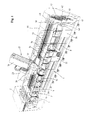
- the machining center for round shown schematically in Figures 1 and 2 Workpieces contain a machine bed 1 and a headstock 2 in which one horizontal workpiece drive spindle 3 with a chuck front workpiece clamping device 4 is arranged rotatably.
- the drive of the Workpiece drive spindle 3 is carried out by one or two parallel drive motors 5 and 6 via a switchable two-stage planetary gear 7, which for a high Operational safety and optimal smoothness ensures.
- the drive can be optimally adapted to the machine.
- the Drive is designed such that it is used both as a rotary drive and as a positioning and Round milling drive can be used.
- the machine bed 1 is a one-piece step bed with a front bed section 8 and a raised rear bed section 9. Between the front bed part 8 and the rear bed part 9 is 1 in the machine bed a chip conveyor 10 for automatic removal of those arising during processing Chips integrated.
- the front bed part 8 contains two parallel guideways 11, which a tailstock 12 guided motor adjustable in a horizontal longitudinal axis is.
- a tailstock housing is adjustable in the longitudinal direction via a motor 13 Quill 14 arranged. In the quill there is an axis with Rotates workpiece speed and in which a tailstock tip 15 is inserted. Between the chuck 4 and the tailstock tip 15 becomes a workpiece 16 to be machined curious; excited.
- the motorized adjustment of the tailstock 12 and the quill 14 guarantee a quick and safe workpiece pick-up. Due to the quill design is a sensitive adjustment of the tailstock to the workpiece possible, which means less axial stiff workpieces can be clamped precisely. In addition, there is a in the quill Integrated spring package, which compensates for the length of the workpiece by e.g. Temperature-related changes in length allowed.
- a large number of different processing units 18 to 24, shown in FIG. 3 arranged with the help of these processing units, different Machining technologies, such as Turning, milling, rotary milling, drilling, 5/6-axis machining, Thread milling, deep drilling, gear cutting and even grinding performed become.
- the support 17 contains a bed slide 26 which via guides 27 on the top of the rear bed part 9 in a to the longitudinal axis of the Workpiece parallel first linear axis 28 (Z axis) can be moved by motor is arranged.
- first linear axis 28 Z axis
- second linear axis 31 Y axis
- a carrier 32 in the form of a stamp in a third linear axis 33 (X axis) perpendicular to the two linear axes 28 and 31 Can be moved across the workpiece.
- an interface 34 is provided, which not only the secure mounting of the different processing units, but also their optimal supply with different media guaranteed.
- a motor is rotatably driven spindle 35, via which the drive of the Processing units are provided that they do not have their own drive.
- FIG 3 are some examples of processing units with the associated Machining examples shown on a rotating part 16.
- On the left is an as Angular head executed drilling or milling unit 18 shown. With this e.g. the end holes in the rotary part 16 are made.
- a machining unit 19 for performing 5/6 axis machining shown.
- This contains a swivel part, which is an additional Axis of rotation is pivotable and is received in a fork-shaped holder. With This additional axis can also be used for complex paths on curved surfaces getting produced. Together with another axis of rotation about the longitudinal axis of the stamp-shaped support can ultimately at any angle in the room standing surfaces are processed.
- this rotating unit 20 e.g. Longitudinal, plan and Contour turning operations are carried out.
- a Milling unit 21 shown with a side milling cutter With this e.g. the shown Slots are made on the outside of the rotating part 16.
- straight Milling unit 22 and a milling unit 23 provided with a motor spindle are shown.
- the processing units can also be high-speed Include attachment spindles that enable high-speed machining.
- a grinding unit is also shown on the right-hand side the conventional machining centers also carried out grinding operations can be.
- the processing units are a device for automatic tool change intended.
- This device consists of a tool magazine 37 and a Tool changer 38 for transporting the workpieces between the tool magazine 37 and a processing unit 18 arranged in the carrier 32.
- the tool changer 38 includes a vertical support bracket 39 that extends over upper and lower guide rails 40 or 41 is arranged to be movable transversely to the longitudinal axis of the machine bed 1.
- a carriage 42 is guided so as to be movable in the vertical axis.
- the Carriage 42 carries tool gripper 43, designed as a double gripper, through which Tool clamped in the processing unit 18 against a tool magazine 37 located tool can be replaced.
- the tool magazine 37 is as Shelf magazine executed, the extension of the machine bed 1 at the end of Machining center is space-saving and can be expanded as required. Also the Tool changing device could, however, on the guideways 11 of the front Bed part 8 can be arranged to be movable.
- lunettes can also be arranged on the front bed part 8 for support. Particularly high accuracy can be achieved with NC-controlled steadies, which are adjustable in all axes.
- the steady rests can be used in a basic version Roller steady rest or for certain tasks as hydrodynamic or hydrostatic Bezel with synchronous or individually adjustable supports.
- the work space encapsulation 44 shown schematically in FIG Work area covered in such a way that all support tours outside the Workspace. This can prevent these guides from becoming dirty protected and their wear can be minimized.
Landscapes
- Engineering & Computer Science (AREA)
- Mechanical Engineering (AREA)
- Turning (AREA)
- Automatic Tool Replacement In Machine Tools (AREA)
Abstract
Description
Die Erfindung betrifft ein Bearbeitungszentrum für runde Werkstücke gemäß dem Oberbegriff des Anspruchs 1.The invention relates to a machining center for round workpieces according to the Preamble of claim 1.
Zur Herstellung im wesentlichen rotationssymmetrischer Werkstücke werden in der Regel Drehmaschinen eingesetzt, bei denen die rotatorische Hauptschnittbewegung vom Werkstück und die Vorschubbewegung vom Werkzeug durchgeführt wird und/oder umgekehrt. Besonders bei den numerisch gesteuerten Drehautomaten gelangen vielfach sogenannte Schrägbettmaschinen zum Einsatz, bei denen der die Werkzeuge tragende Support an einer schrägen Führungsfläche des Maschinenbetts angeordnet ist. Zur Durchführung mehrerer Bearbeitungsoperationen mit unterschiedlichen Werkzeugen sind an dem Support z.B. als Stern- , Scheibenrevolver oder Bohr- und Fräsaggregat ausgeführte Werkzeugträgersysteme vorgesehen. In derartige Trägersysteme können auch kleinere Bearbeitungseinheiten eingesetzt werden, mit denen bestimmte Fräs- oder Bohrbearbeitungen möglich sind. Allerdings sind die Bewegungsmöglichkeiten derartiger Werkzeugträgersysteme aufgrund der Kollisionsgefahr mit den Werkstücken beschränkt. Durch die Störkonturen der Bearbeitungseinheiten können daher eine Reihe von Bearbeitungsoperationen entweder gar nicht oder nur mit erheblichem Aufwand durchgeführt werden. Viele Konzepte zur Erweiterung des Bearbeitungsspektrums stellen daher Kompromißlösungen dar, die nur auf ein spezielles Einsatzgebiet abgestimmt sind.For the production of essentially rotationally symmetrical workpieces in the Usually lathes are used, in which the rotary main cutting movement from Workpiece and the feed movement is carried out by the tool and / or vice versa. Especially with the numerically controlled automatic lathes so-called inclined bed machines are used, in which the person carrying the tools Support is arranged on an inclined guide surface of the machine bed. to Execution of several machining operations with different tools are at the support e.g. as a star, disc turret or drilling and milling unit executed tool carrier systems provided. In such carrier systems can also smaller processing units can be used with which certain milling or Drilling operations are possible. However, the movement options Such tool carrier systems due to the risk of collision with the workpieces limited. Due to the interfering contours of the processing units, a number can be created of machining operations either not at all or only with considerable effort be performed. Many concepts for expanding the processing spectrum therefore represent compromise solutions that only apply to a specific area of application are coordinated.
Aufgabe der Erfindung ist es, ein Bearbeitungszentrum der eingangs genannten Art zu schaffen, das eine Komplettbearbeitung von runden Werkstücken in einer Aufspannung ermöglicht.The object of the invention is to provide a machining center of the type mentioned create a complete machining of round workpieces in one clamping allows.
Diese Aufgabe wird durch ein Bearbeitungszentrum mit den Merkmalen des Anspruchs 1 gelöst. Zweckmäßige Ausgestaltungen und vorteilhafte Weiterbildungen der Erfindung sind in den Unteransprüchen angegeben. This task is performed by a machining center with the features of the claim 1 solved. Appropriate refinements and advantageous developments of the Invention are specified in the subclaims.
Das erfindungsgemäße Bearbeitungszentrum zeichnet sich durch ein breites Einsatzspektrum bei gleichzeitig hoher statischer und dynamischer Steifigkeit aus. Neben der klassischen Drehbearbeitung können auch eine Vielzahl weiterer Bearbeitungstechnologien, wie Fräsen, Bohren, Drehfräsen, 5/6-Achsbearbeitung, Gewindefräsen, Tiefbohren, Verzahnen und insbesondere auch Schleifen mit hoher Genauigkeit in einer Werkstückaufspannung durchgeführt werden. Dadurch wird eine Komplettbearbeitung auch größerer und komplex geformter runder und asymmetrischer Werkstücke ohne Umspannung möglich. Die einfache Austauschbarkeit der unterschiedlichen Bearbeitungseinheiten gewährleistet eine hohe Produktivität und optimale Wirtschaftlichkeit. Der modulare Aufbau ermöglicht außerdem eine nachträgliche Erweiterung durch Adaption entsprechender Bearbeitungseinheiten. Dadurch kann eine ursprünglich für andere Bearbeitungsaufgaben vorgesehene Maschine mit neuen Technologien erweitert werden.The machining center according to the invention is characterized by a broad Range of applications with high static and dynamic rigidity. In addition to classic turning, a variety of others can also be used Machining technologies, such as milling, drilling, rotary milling, 5/6 axis machining, Thread milling, deep drilling, gear cutting and especially grinding with high Accuracy can be carried out in a workpiece clamping. This will make one Complete machining of larger and more complex shaped round and asymmetrical Workpieces possible without reclamping. The easy interchangeability of the different processing units ensures high productivity and optimal economy. The modular structure also enables one subsequent expansion by adapting the corresponding processing units. This means that one originally intended for other machining tasks Machine can be expanded with new technologies.
Ein weiterer wesentlicher Vorteil des erfindungsgemäßen Maschinenkonzepts besteht in der optimalen Späneabfuhr. Die bei der Bearbeitung anfallenden Späne können frei nach unten fallen und bleiben nicht auf verschiebbaren Supportteilen oder entsprechenden Abdeckungen liegen. Zur optimale Abfuhr der nach unten fallenden Späne aus der Maschine ist in einer vorteilhaften Ausführung ein automatischer Späneförderer im Maschinenbett integriert.Another significant advantage of the machine concept according to the invention is in the optimal chip removal. The chips generated during processing can be freely added fall below and do not remain on sliding support parts or equivalent Covers are lying. For optimal removal of the chips falling down from the In an advantageous embodiment, the machine is an automatic chip conveyor in the Integrated machine bed.
Der die unterschiedlichen Bearbeitungseinheiten aufnehmende Träger ist in einer besonders zweckmäßigen Ausführung in einer Art pinolenförmigen Stempel ausgeführt. Er befindet sich in einer schräg angeordneten Spindelstockeinheit, die wiederum auf einer schlittenförmigen, verfahrbaren Trägereinheit auf dem Bett verfahren werden kann. Der Stempel ist im oberen Spindelstock in Richtung des Werkzeugs schräg von oben nach unten, nc-gesteuert, verfahrbar. Dadurch wird eine optimale Arbeitsraumfreiheit am Bearbeitungsmodul gewährleistet und die Kollisionsgefahr verringert. In dem pinolenartigen Stempel ist eine motorisch angetriebene Antriebsspindel angeordnet. Dadurch können die unterschiedlichen Bearbeitungseinheiten durch eine zentrale Einheit angetrieben werden, sofern sie keinen eigenständigen Antrieb (Motorspindeln) besitzen. The carrier holding the different processing units is in one particularly expedient execution in a kind of quill-shaped stamp. It is located in an inclined headstock unit, which in turn is on a sled-shaped, movable carrier unit can be moved on the bed can. The punch is oblique in the upper headstock in the direction of the tool top down, NC controlled, movable. This will be an optimal one Guaranteed freedom of work space on the processing module and the risk of collision reduced. In the quill-like stamp is a motor-driven one Drive spindle arranged. This allows the different Machining units are driven by a central unit, provided they do not own drive (motor spindles).
In einer besonders soliden und formsteifen Ausgestaltung ist das Maschinenbett als Stufenbett mit einem vorderen Bettteil und einem erhöhten hinteren Bettteil ausgeführt. Dadurch können auch große und schwere Bauteile mit einer hohen Genauigkeit bearbeitet werden.The machine bed is in a particularly solid and dimensionally stable design Step bed with a front bed section and a raised rear bed section. This means that even large and heavy components can be machined with high accuracy to be edited.
Der Antrieb der Hauptspindel erfolgt in einer weiteren zweckmäßigen Ausführung über einen oder zwei parallele Antriebsmotore. Dadurch ist eine optimale Anpassung des Antriebs an die unterschiedlichen Leistungsanforderungen möglich. Der Antrieb ist als Dreh-, Positionier- und Rundfräsantrieb ausgeführt.In a further expedient version, the main spindle is driven by one or two parallel drive motors. This is an optimal adjustment of the Drive to the different performance requirements possible. The drive is as Rotary, positioning and round milling drive.
In einer weiteren Ausgestaltung ist an dem vorderen Bettteil, am Ende des Maschinenbetts, ein Magazin für die zum Einsatz gelangenden Bearbeitungseinheiten angeordnet. Dadurch können die Bearbeitungseinheiten durch einfache Verfahrbewegungen des Supports im Pick-up-Verfahren ausgetauscht werden.In a further embodiment, on the front bed part, at the end of the Maschinenbetts, a magazine for the processing units used arranged. As a result, the processing units can be changed by simple Traversing movements of the support can be exchanged using the pick-up procedure.
Zum schnellen und effizienten automatischen Austauschs der Werkzeuge ist außerdem am Ende der Maschine ein Werkzeugmagazin mit einem zugehörigen automatischen Werkzeugwechsler vorgesehen.For quick and efficient automatic exchange of tools is also at the end of the machine, a tool magazine with an associated automatic Tool changer provided.
Weitere Besonderheiten und Vorzüge der Erfindung ergeben sich aus der folgenden Beschreibung eines bevorzugten Ausführungsbeispiels anhand der Zeichnung. Es zeigt:
- Figur 1
- eine schematische Gesamtdarstellung eines erfindungsgemäßen Bearbeitungszentrums für runde Werkstücke in einer Perspektive;
-
Figur 2 - den Grundaufbau des in Figur 1 gezeigten Bearbeitungszentrums in einer Vorderansicht, Seitenansicht und Draufsicht und
-
Figur 3 - verschiedene Bearbeitungseinheiten zur Durchführung unterschiedlicher Bearbeitungstechnologien an einem runden Werkstück.
- Figure 1
- a schematic overall view of a machining center according to the invention for round workpieces in one perspective;
- Figure 2
- the basic structure of the machining center shown in Figure 1 in a front view, side view and top view and
- Figure 3
- Different processing units for the implementation of different processing technologies on a round workpiece.
Das in den Figuren 1 und 2 schematisch dargestellte Bearbeitungszentrum für runde
Werkstücke enthält ein Maschinenbett 1 und einen Spindelstock 2, in dem eine
horizontale Werkstückantriebsspindel 3 mit einer als Spannfutter ausgeführten
stirnseitigen Werkstückspannvorrichtung 4 drehgelagert angeordnet ist. Der Antrieb der
Werkstückantriebsspindel 3 erfolgt durch ein oder zwei parallele Antriebsmotoren 5 und
6 über je ein schaltbares zweistufiges Planetengetriebe 7, das für eine hohe
Betriebssicherheit und eine optimale Laufruhe sorgt. Durch Konfiguration einer
Maschine mit ein oder zwei der als Drehstrommotoren ausgeführten Antriebsmotoren 5
und 6 kann der Antrieb in optimaler Weise an die Maschine angepaßt werden. Der
Antrieb ist derart ausgelegt, daß er sowohl als Drehantrieb als auch als Positionier- und
Rundfräsantrieb genutzt werden kann.The machining center for round shown schematically in Figures 1 and 2
Workpieces contain a machine bed 1 and a
Wie besonders aus Figur 2 hervorgeht, ist das Maschinenbett 1 als einteiliges Stufenbett
mit einem vorderen Bettteil 8 und einem erhöhten hinteren Bettteil 9 ausgeführt.
Zwischen dem vorderen Bettteil 8 und dem hinteren Bettteil 9 ist im Maschinenbett 1
ein Späneförderer 10 zur automatischen Abfuhr der bei der Bearbeitung anfallenden
Späne integriert. Der vordere Bettteil 8 enthält zwei parallele Führungsbahnen 11, auf
denen ein Reitstock 12 in einer horizontalen Längsachse motorisch verstellbar geführt
ist. In dem Reitstockgehäuse ist eine über einen Motor 13 in Längsrichtung verstellbare
Pinole 14 angeordnet. In der Pinole befindet sich eine Achse, die mit
Werkstückdrehzahl umläuft und in die eine Reitstockspitze 15 eingesetzt ist. Zwischen
dem Spannfutter 4 und der Reitstockspitze 15 wird ein zu bearbeitendes Werkstück 16
gespannt. Die motorische Verstellung des Reitstocks 12 und der Pinole 14 garantieren
eine schnelle und sicherere Werkstückaufnahme. Durch die Pinolenausführung ist ein
feinfühliges Anstellen des Reitstocks an das Werkstück möglich, wodurch axial weniger
steife Werkstücke laufgenau gespannt werden können. Zusätzlich ist in der Pinole ein
Federpaket integriert, das einen Längenausgleich des Werkstückes durch z.B.
temperaturbedingte Längenänderungen erlaubt.As can be seen particularly from FIG. 2, the machine bed 1 is a one-piece step bed
with a
Auf dem hinteren Bettteil 9 ist ein Support 17 mit Spindelstock für die Aufnahme einer
Vielzahl unterschiedlicher - in Figur 3 dargestellter - Bearbeitungseinheiten 18 bis 24
angeordnet Mit Hilfe dieser Bearbeitungseinheiten können verschiedene
Bearbeitungstechnologien, wie z.B. Drehen, Fräsen, Drehfräsen, Bohren, 5/6-Achs-Bearbeitung,
Gewindefräsen, Tiefbohren, Verzahnen und sogar Schleifen durchgeführt
werden.On the
Wie besonders aus Figur 2 hervorgeht, enthält der Support 17 einen Bettschlitten 26, der
über Führungen 27 auf der Oberseite des hinteren Bettteils 9 in einer zur Längsachse des
Werkstücks parallelen ersten Linearachse 28 (Z-Achse) motorisch verfahrbar
angeordnet ist. An der Seite eines unter 45° nach nach oben abgeköpften oberen Teils
29 des Bettschlittens 26 ist ein oberer Spindelstock 30 in einer unter 45° zur
Horizontalen geneigten zweiten Linearachse 31 (Y-Achse) motorisch verfahrbar
angeordnet. In dem Spindelstock 30 ist ein in Art eines Stempels ausgeführter Träger 32
in einer zu den beiden Linearachsen 28 und 31 senkrechten dritten Linearachse 33 (X-Achse)
quer zum Werkstück verfahrbar geführt. An dem vorderen Ende des Trägers 32
ist eine Schnittstelle 34 vorgesehen, die nicht nur die sichere Halterung der
unterschiedlichen Bearbeitungseinheiten, sondern auch deren optimale Versorgung mit
unterschiedlichen Medien gewährleistet. In dem rechteckigen Träger 32 ist eine durch
einen Motor drehangetriebene Spindel 35 angeordnet, über die der Antrieb der
Bearbeitungseinheiten erfolgt, sofern sie keinen eigenen Antrieb besitzen.As can be seen particularly from FIG. 2, the
In Figur 3 sind einige Beispiele für Bearbeitungseinheiten mit den zugehörigen
Bearbeitungsbeispielen auf einem Drehteil 16 gezeigt. Auf der linken Seite ist eine als
Winkelkopf ausgeführte Bohr- oder Fräseinheit 18 gezeigt. Hiermit können z.B. die
stirnseitigen Bohrungen in dem Drehteil 16 hergestellt werden. Neben der Bohr- und
Fräseinheit 18 ist eine Bearbeitungseinheit 19 zur Durchführung einer 5/6-Achsen-Bearbeitung
dargestellt. Diese enthält ein Schwenkteil, das um eine zusätzliche
Drehachse schwenkbar ist und in einer gabelförmigen Halterung aufgenommen ist. Mit
dieser weiteren Achse können auch komplexe Bahnen an gekrümmten Flächen
hergestellt werden. Zusammen mit einer weiteren Drehachse um die Längsachse des
stempelförmigen Trägers können letztendlich unter beliebigen Winkeln im Raum
stehende Flächen bearbeitet werden. Daneben ist eine Dreheinheit 20 mit einer
stimseitigen und seitlichen Halterung zur Aufnahme von Werkzeugen aus modularen
Werkzeugsystemen dargestellt. Mit dieser Dreheinheit 20 können z.B. Längs-, Plan- und
Konturdrehoperationen durchgeführt werden. Neben der Dreheinheit 20 ist eine
Fräseinheit 21 mit einem Scheibenfräser gezeigt. Hiermit können z.B. die gezeigten
Schlitze an der Außenseite des Drehteils 16 hergestellt werden. Weiter sind eine gerade
Fräseinheit 22 und eine mit Motorspindel versehene Fräseinheit 23 dargestellt. Durch
gesteuerte Drehung der Hauptantriebsspindel können so z.B. auch komplexe
Verzahnungen gefräst werden. Die Bearbeitungseinheiten können auch schnelllaufende
Vorsatzspindeln beinhalten, die eine Hochgeschwindigkeitsbearbeitung ermöglichen.
Auf der rechten Seite ist außerdem eine Schleifeinheit gezeigt, mit der im Gegensatz zu
den herkömmlichen Bearbeitungszentren auch Schleifbearbeitungen durchgeführt
werden können.In Figure 3 are some examples of processing units with the associated
Machining examples shown on a
Zum automatischen Wechsel der zum Einsatz kommenden Bearbeitungseinheiten ist am
Ende des vorderen Bettteils 8 ein auch in der Seitenansicht der Figur 2 dargestelltes
Magazin 36 zur Bereitstellung der Bearbeitungseinheiten angeordnet. In diesem
Magazin 36 sind die Bearbeitungeinheiten unter 45° liegend derart angeordnet, daß sie
durch einfache Verfahrbewegungen des Supports 17 von dem Träger 32 einfach
aufgenommen bzw. von diesem entsprechend abgelegt werden können. Bei der
gezeigten Ausführung ist das modular erweiterbare Magazin 36 stationär am Ende des
Maschinenbetts 1 angeordnet. Es könnte aber auch verschiebbar auf den
Führungsbahnen 11 des vorderen Bettteils 8 angeordnet sein. Dadurch kann der vom
Bettschlitten 26 zur Auswechslung zurückzulegende Verfahrweg verkürzt werden, wenn
vornehmlich kürzere Werkstücke bearbeitet werden.To automatically change the processing units used, is on
End of the
Zum schnellen und effizienten Austausch der Werkzeuge ist neben dem Magazin 36 für
die Bearbeitungseinheiten eine Einrichtung zum automatischen Werkzeugwechsel
vorgesehen. Diese Einrichtung besteht aus einem Werkzeugmagazin 37 und einem
Werkzeugwechsler 38 zum Transport der Werkstücke zwischen dem Werkzeugmagazin
37 und einer im Träger 32 angeordneten Bearbeitungseinheit 18. Der Werkzeugwechsler
38 enthält eine vertikalen Trägerstütze 39, die über obere und untere Führungsschienen
40 bzw. 41 quer zur Längsachse des Maschinenbetts 1 verfahrbar angeordnet ist. An der
Trägerstütze 39 ist ein Schlitten 42 in der Vertikalachse verfahrbar geführt. Der
Schlitten 42 trägt den als Doppelgreifer ausgeführten Werkzeuggreifer 43, durch den ein
in der Bearbeitungseinheit 18 gespanntes Werkzeug gegen ein im Werkzeugmagazin 37
befindliches Werkzeug ausgetauscht werden kann. Das Werkzeugmagazin 37 ist als
Regalmagazin ausgeführt, das in Verlängerung des Maschinenbetts 1 am Ende des
Bearbeitungszentrums platzsparend angeordnet und beliebig erweiterbar ist. Auch die
Werkzeugwechseleinrichtung könnte jedoch auf den Führungsbahnen 11 des vorderen
Bettteils 8 verfahrbar angeordnet sein.In addition to the
Zur Vermeidung von Durchbiegungen besonders an langen und schlanken Werkstücken
können auf dem vorderen Bettteil 8 auch Lünetten zur Abstützung angeordnet werden.
Eine besonders hohe Genauigkeit läßt sich durch NC-gesteuerte Lünetten erreichen, die
in allen Achsen gesteuert verstellbar sind. Die Lünetten können in einer Basisversion als
Rollenlünette oder für bestimmte Aufgaben als hydrodynamische oder hydrostatische
Lünette mit synchron oder individuell anstellbaren Auflagen ausgeführt sein.To avoid bending, especially on long and slim workpieces
lunettes can also be arranged on the
Durch eine in Figur 1 schematisch dargestellte Arbeitsraumkapselung 44 wird der
Arbeitsraum derart abgedeckt, daß sich sämtliche Supportführungen außerhalb des
Arbeitsbereichs befinden. Dadurch können diese Führungen vor Verschmutzung
geschützt und deren Verschleiß kann minimiert werden.The
Claims (15)
einem Maschinenbett (1),
einer in einem seitlichen Spindelstock (2) am Maschinenbett (1) drehbar gelagerten und durch einen Antrieb (5, 6, 7) drehangetriebenen horizontalen Hauptantriebsspindel (3) mit einer Werkstückspannvorrichtung (4),
einem auf dem Maschinenbett (1) angeordneten Reitstock (12) und
einem auf dem Maschinenbett (1) verfahrbar angeordneten Support (17),
dadurch gekennzeichnet, daß der Support (17) einen auf dem Maschinenbett (1) verfahrbaren Bettschlitten (26) und einen an diesem schräg angeordneten oberen Spindelstock (30) mit einem in dessen Längsachse verfahrbaren Träger (32) aufweist, in den austauschbare Bearbeitungseinheiten (18, 19, 20, 21, 22, 23, 24) zur Durchführung unterschiedlicher Bearbeitungstechnologien einsetzbar sind.Machining center for round workpieces with
a machine bed (1),
a horizontal main drive spindle (3) rotatably mounted in a lateral headstock (2) on the machine bed (1) and driven by a drive (5, 6, 7) with a workpiece clamping device (4),
a tailstock (12) arranged on the machine bed (1) and
a support (17) arranged movably on the machine bed (1),
characterized in that the support (17) has a bed slide (26) which can be moved on the machine bed (1) and an upper headstock (30) arranged obliquely thereon with a carrier (32) which can be moved in its longitudinal axis, into which exchangeable processing units (18 , 19, 20, 21, 22, 23, 24) can be used to implement different machining technologies.
Applications Claiming Priority (2)
| Application Number | Priority Date | Filing Date | Title |
|---|---|---|---|
| DE10144679 | 2001-09-11 | ||
| DE10144679A DE10144679A1 (en) | 2001-09-11 | 2001-09-11 | machining center |
Publications (2)
| Publication Number | Publication Date |
|---|---|
| EP1291130A2 true EP1291130A2 (en) | 2003-03-12 |
| EP1291130A3 EP1291130A3 (en) | 2003-07-02 |
Family
ID=7698596
Family Applications (1)
| Application Number | Title | Priority Date | Filing Date |
|---|---|---|---|
| EP02017560A Withdrawn EP1291130A3 (en) | 2001-09-11 | 2002-08-07 | Machining centre for round workpieces |
Country Status (4)
| Country | Link |
|---|---|
| US (1) | US20030069115A1 (en) |
| EP (1) | EP1291130A3 (en) |
| JP (1) | JP2003094205A (en) |
| DE (1) | DE10144679A1 (en) |
Cited By (7)
| Publication number | Priority date | Publication date | Assignee | Title |
|---|---|---|---|---|
| WO2014170367A1 (en) | 2013-04-19 | 2014-10-23 | Heinrich Georg Gmbh Maschinenfabrik | Machining center, in particular rotating/boring/milling/grinding center for machining workpieces |
| CN104647104A (en) * | 2015-02-13 | 2015-05-27 | 苏州江源精密机械有限公司 | Rotary accessory head automatic replacing head library device for gantry machining center |
| CN104647105A (en) * | 2015-02-13 | 2015-05-27 | 苏州江源精密机械有限公司 | Accessory head automatic replacing head library device for gantry machining center |
| EP3456463A1 (en) * | 2017-09-14 | 2019-03-20 | AFW Holding GmbH | Machining head for in particular, mechanical cutting, machining and in particular for controlling the level of a workpiece |
| EP3581327A4 (en) * | 2017-02-07 | 2020-11-04 | Makino Milling Machine Co., Ltd. | Machine tool |
| CN114290130A (en) * | 2021-12-25 | 2022-04-08 | 九众九机器人有限公司 | Workpiece contour machining process |
| CN115365835A (en) * | 2022-09-27 | 2022-11-22 | 南通国盛智能科技集团股份有限公司 | Bridge type gantry machining center |
Families Citing this family (3)
| Publication number | Priority date | Publication date | Assignee | Title |
|---|---|---|---|---|
| DE102006017664A1 (en) * | 2006-04-12 | 2007-10-18 | Volkswagen Ag | CAD/CAM process to fabricate master press tool for automotive body panel finished by spring-applied polishing tool and diamond paste |
| DE102009020023A1 (en) * | 2009-05-05 | 2010-11-11 | Liebherr-Verzahntechnik Gmbh | Gear-cutting machine for machining workpiece for producing gear wheels, has universal cutting surface coupling machine unit with own control unit such that gear-cutting machine is expandable around any auxiliary working operation |
| US9586299B2 (en) * | 2014-12-08 | 2017-03-07 | Jpw Industries Inc. | Non-slip mat for lathe |
Citations (6)
| Publication number | Priority date | Publication date | Assignee | Title |
|---|---|---|---|---|
| EP0239564A2 (en) * | 1986-03-26 | 1987-09-30 | Maschinenfabrik Heid Aktiengesellschaft | Turning machine |
| JPS63191530A (en) * | 1987-01-30 | 1988-08-09 | Yamazaki Mazak Corp | Working for workpiece on complex working machine tool |
| EP0314824A1 (en) * | 1987-11-03 | 1989-05-10 | Waldrich Siegen Werkzeugmaschinenbau GmbH | Universal milling machine with several axles |
| US5289622A (en) * | 1991-03-11 | 1994-03-01 | Dainichi Kinzoku Kogyo Kabushiki Kaisha | Carriage structure of NC lathe |
| US5490307A (en) * | 1991-10-19 | 1996-02-13 | Index-Werke Gmbh & Co. Kg Hahn & Tessky | Lathe |
| EP0900627A2 (en) * | 1997-09-04 | 1999-03-10 | Mori Seiki Co., Ltd. | Multi-function lathe |
Family Cites Families (14)
| Publication number | Priority date | Publication date | Assignee | Title |
|---|---|---|---|---|
| BE386933A (en) * | 1931-12-28 | 1900-01-01 | ||
| GB1223565A (en) * | 1967-06-26 | 1971-02-24 | Wickman Mach Tool Sales Ltd | Turning machines |
| CH510488A (en) * | 1969-05-20 | 1971-07-31 | Dubied & Cie Sa E | Lathe |
| US3894808A (en) * | 1971-08-06 | 1975-07-15 | Vincent Zarlengo | Mount adapter for cutting tools and method of operating |
| AT378710B (en) * | 1983-12-01 | 1985-09-25 | Voest Alpine Ag | LATHE |
| DE3410276A1 (en) * | 1984-03-17 | 1984-10-31 | H. Wohlenberg KG - GmbH & Co, 3000 Hannover | LATHE |
| US4701818A (en) * | 1986-02-18 | 1987-10-20 | Magnetic Peripherals Inc. | Means for indexing a rotary arm in small angular steps |
| JPS6374534A (en) * | 1986-09-12 | 1988-04-05 | Tsugami Corp | Complex machining machine tool |
| FR2641220B1 (en) * | 1988-05-25 | 1994-06-03 | Somab Sa | MULTIPURPOSE MACHINE TOOL FOR COMPLEX LONG PIECE MACHINING |
| US5111562A (en) * | 1990-11-27 | 1992-05-12 | Versa Tech Engineering | Spindle apparatus for holding a workpiece |
| JPH04269137A (en) * | 1991-02-20 | 1992-09-25 | Tsugami Corp | Composite work machine tool |
| DE4414856C2 (en) * | 1994-04-28 | 1997-03-27 | Max Mueller Werkzeugmaschinen | Lathe with a tool tower for holding non-rotating and rotating tools |
| US5885199A (en) * | 1996-02-06 | 1999-03-23 | Shao; Wenyuan | Compact machining center for multifunction |
| JP3167644B2 (en) * | 1997-06-20 | 2001-05-21 | 株式会社森精機製作所 | Tool spindle fixing device for compound machine tools |
-
2001
- 2001-09-11 DE DE10144679A patent/DE10144679A1/en not_active Withdrawn
-
2002
- 2002-08-07 EP EP02017560A patent/EP1291130A3/en not_active Withdrawn
- 2002-08-29 US US10/233,317 patent/US20030069115A1/en not_active Abandoned
- 2002-09-11 JP JP2002265777A patent/JP2003094205A/en not_active Withdrawn
Patent Citations (6)
| Publication number | Priority date | Publication date | Assignee | Title |
|---|---|---|---|---|
| EP0239564A2 (en) * | 1986-03-26 | 1987-09-30 | Maschinenfabrik Heid Aktiengesellschaft | Turning machine |
| JPS63191530A (en) * | 1987-01-30 | 1988-08-09 | Yamazaki Mazak Corp | Working for workpiece on complex working machine tool |
| EP0314824A1 (en) * | 1987-11-03 | 1989-05-10 | Waldrich Siegen Werkzeugmaschinenbau GmbH | Universal milling machine with several axles |
| US5289622A (en) * | 1991-03-11 | 1994-03-01 | Dainichi Kinzoku Kogyo Kabushiki Kaisha | Carriage structure of NC lathe |
| US5490307A (en) * | 1991-10-19 | 1996-02-13 | Index-Werke Gmbh & Co. Kg Hahn & Tessky | Lathe |
| EP0900627A2 (en) * | 1997-09-04 | 1999-03-10 | Mori Seiki Co., Ltd. | Multi-function lathe |
Non-Patent Citations (1)
| Title |
|---|
| PATENT ABSTRACTS OF JAPAN vol. 012, no. 466 (M-772), 7. Dezember 1988 (1988-12-07) & JP 63 191530 A (YAMAZAKI MAZAK CORP), 9. August 1988 (1988-08-09) * |
Cited By (12)
| Publication number | Priority date | Publication date | Assignee | Title |
|---|---|---|---|---|
| WO2014170367A1 (en) | 2013-04-19 | 2014-10-23 | Heinrich Georg Gmbh Maschinenfabrik | Machining center, in particular rotating/boring/milling/grinding center for machining workpieces |
| DE102013207125A1 (en) | 2013-04-19 | 2014-10-23 | Heinrich Georg Gmbh Maschinenfabrik | Machining center, in particular turning / drilling / milling / grinding center for machining workpieces |
| CN104647104A (en) * | 2015-02-13 | 2015-05-27 | 苏州江源精密机械有限公司 | Rotary accessory head automatic replacing head library device for gantry machining center |
| CN104647105A (en) * | 2015-02-13 | 2015-05-27 | 苏州江源精密机械有限公司 | Accessory head automatic replacing head library device for gantry machining center |
| CN104647105B (en) * | 2015-02-13 | 2017-10-20 | 苏州江源精密机械有限公司 | Additional header changes a storehouse device automatically on gantry machining center |
| EP3581327A4 (en) * | 2017-02-07 | 2020-11-04 | Makino Milling Machine Co., Ltd. | Machine tool |
| US11407071B2 (en) | 2017-02-07 | 2022-08-09 | Makino Milling Machine Co., Ltd. | Machine tool |
| EP3456463A1 (en) * | 2017-09-14 | 2019-03-20 | AFW Holding GmbH | Machining head for in particular, mechanical cutting, machining and in particular for controlling the level of a workpiece |
| WO2019052853A1 (en) * | 2017-09-14 | 2019-03-21 | Afw Holding Gmbh | Machining head for the mechanical, in particular cutting, machining of a workpiece |
| US11945068B2 (en) | 2017-09-14 | 2024-04-02 | Afw Holding Gmbh | Machining head for the mechanical, in particular cutting, machining of a workpiece |
| CN114290130A (en) * | 2021-12-25 | 2022-04-08 | 九众九机器人有限公司 | Workpiece contour machining process |
| CN115365835A (en) * | 2022-09-27 | 2022-11-22 | 南通国盛智能科技集团股份有限公司 | Bridge type gantry machining center |
Also Published As
| Publication number | Publication date |
|---|---|
| DE10144679A1 (en) | 2003-03-27 |
| EP1291130A3 (en) | 2003-07-02 |
| JP2003094205A (en) | 2003-04-03 |
| US20030069115A1 (en) | 2003-04-10 |
Similar Documents
| Publication | Publication Date | Title |
|---|---|---|
| EP1291122B1 (en) | Machining centre for milling and drilling | |
| EP1046461B1 (en) | Universal machine tool | |
| DE68909889T2 (en) | MACHINE TOOL FOR MULTIPLE MACHINING TYPES AND FOR THE COMPLEX MACHINING OF LONG WORKPIECES. | |
| EP1338376B1 (en) | Milling machine for milling and turning rod shaped material | |
| DE3721610C2 (en) | ||
| DE102004061318B4 (en) | Machine tool with tool changer | |
| DE60303672T2 (en) | MACHINE TOOL | |
| DE3427245A1 (en) | MACHINE TOOL | |
| DE3420531C2 (en) | Automatic lathe | |
| EP1413395A1 (en) | Machine tool | |
| EP0995539A2 (en) | Machining device for work pieces | |
| DE8915924U1 (en) | Drilling and milling machine | |
| DE2033026B2 (en) | NC-controlled machining center for workpieces to be machined by turning from both sides as well as by milling and / or drilling | |
| DE102010051865A1 (en) | Two-axis machine tool for milling rotationally driven workpiece, has workpiece spindle and tool holder moved relative to each other such that engagement of tool at workpiece is performed on set of sides of planes opposite to column | |
| DE102006042006B4 (en) | lathe | |
| DE10034973C2 (en) | Universal machine tool with workpiece carriers that can be changed in pick-up mode | |
| DE10307977C5 (en) | Method and device for processing differential housings | |
| EP1294530B1 (en) | Machine tool for processing work pieces on at least three axes | |
| EP1291130A2 (en) | Machining centre for round workpieces | |
| DE2409773B2 (en) | CURVELESS PROGRAM-CONTROLLED MULTI-SPINDLE AUTOMATIC LATHE | |
| EP3784432A1 (en) | Machine tool having a work spindle on an inclined surface | |
| DE3530982A1 (en) | Two-spindle numerically controlled lathe | |
| EP3624988B1 (en) | Machine-tool | |
| DE20115005U1 (en) | Milling and drilling machining center | |
| DE3824572C2 (en) |
Legal Events
| Date | Code | Title | Description |
|---|---|---|---|
| PUAI | Public reference made under article 153(3) epc to a published international application that has entered the european phase |
Free format text: ORIGINAL CODE: 0009012 |
|
| AK | Designated contracting states |
Kind code of ref document: A2 Designated state(s): AT BE BG CH CY CZ DE DK EE ES FI FR GB GR IE IT LI LU MC NL PT SE SK TR Designated state(s): AT BE BG CH CY CZ DE DK EE ES FI FR GB GR IE IT LI LU MC NL PT SE SK TR |
|
| AX | Request for extension of the european patent |
Extension state: AL LT LV MK RO SI |
|
| PUAL | Search report despatched |
Free format text: ORIGINAL CODE: 0009013 |
|
| AK | Designated contracting states |
Designated state(s): AT BE BG CH CY CZ DE DK EE ES FI FR GB GR IE IT LI LU MC NL PT SE SK TR |
|
| AX | Request for extension of the european patent |
Extension state: AL LT LV MK RO SI |
|
| RIC1 | Information provided on ipc code assigned before grant |
Ipc: 7B 23Q 3/155 B Ipc: 7B 23B 3/16 B Ipc: 7B 23Q 1/62 B Ipc: 7B 23Q 1/01 B Ipc: 7B 23Q 39/02 B Ipc: 7B 23Q 37/00 A |
|
| 17P | Request for examination filed |
Effective date: 20031010 |
|
| AKX | Designation fees paid |
Designated state(s): AT BE BG CH CY CZ DE DK EE ES FI FR GB GR IE IT LI LU MC NL PT SE SK TR |
|
| STAA | Information on the status of an ep patent application or granted ep patent |
Free format text: STATUS: THE APPLICATION IS DEEMED TO BE WITHDRAWN |
|
| 18D | Application deemed to be withdrawn |
Effective date: 20060301 |