EP1291067A2 - Schnelle Wechseltemperaturabsorption - Google Patents
Schnelle Wechseltemperaturabsorption Download PDFInfo
- Publication number
- EP1291067A2 EP1291067A2 EP02255859A EP02255859A EP1291067A2 EP 1291067 A2 EP1291067 A2 EP 1291067A2 EP 02255859 A EP02255859 A EP 02255859A EP 02255859 A EP02255859 A EP 02255859A EP 1291067 A2 EP1291067 A2 EP 1291067A2
- Authority
- EP
- European Patent Office
- Prior art keywords
- adsorbent
- gas
- feed gas
- adsorber
- component
- Prior art date
- Legal status (The legal status is an assumption and is not a legal conclusion. Google has not performed a legal analysis and makes no representation as to the accuracy of the status listed.)
- Withdrawn
Links
Images

Classifications
-
- B—PERFORMING OPERATIONS; TRANSPORTING
- B01—PHYSICAL OR CHEMICAL PROCESSES OR APPARATUS IN GENERAL
- B01D—SEPARATION
- B01D53/00—Separation of gases or vapours; Recovering vapours of volatile solvents from gases; Chemical or biological purification of waste gases, e.g. engine exhaust gases, smoke, fumes, flue gases, aerosols
- B01D53/02—Separation of gases or vapours; Recovering vapours of volatile solvents from gases; Chemical or biological purification of waste gases, e.g. engine exhaust gases, smoke, fumes, flue gases, aerosols by adsorption, e.g. preparative gas chromatography
- B01D53/04—Separation of gases or vapours; Recovering vapours of volatile solvents from gases; Chemical or biological purification of waste gases, e.g. engine exhaust gases, smoke, fumes, flue gases, aerosols by adsorption, e.g. preparative gas chromatography with stationary adsorbents
- B01D53/0462—Temperature swing adsorption
-
- B—PERFORMING OPERATIONS; TRANSPORTING
- B01—PHYSICAL OR CHEMICAL PROCESSES OR APPARATUS IN GENERAL
- B01D—SEPARATION
- B01D2253/00—Adsorbents used in seperation treatment of gases and vapours
- B01D2253/10—Inorganic adsorbents
- B01D2253/104—Alumina
-
- B—PERFORMING OPERATIONS; TRANSPORTING
- B01—PHYSICAL OR CHEMICAL PROCESSES OR APPARATUS IN GENERAL
- B01D—SEPARATION
- B01D2253/00—Adsorbents used in seperation treatment of gases and vapours
- B01D2253/10—Inorganic adsorbents
- B01D2253/106—Silica or silicates
- B01D2253/108—Zeolites
-
- B—PERFORMING OPERATIONS; TRANSPORTING
- B01—PHYSICAL OR CHEMICAL PROCESSES OR APPARATUS IN GENERAL
- B01D—SEPARATION
- B01D2253/00—Adsorbents used in seperation treatment of gases and vapours
- B01D2253/25—Coated, impregnated or composite adsorbents
-
- B—PERFORMING OPERATIONS; TRANSPORTING
- B01—PHYSICAL OR CHEMICAL PROCESSES OR APPARATUS IN GENERAL
- B01D—SEPARATION
- B01D2257/00—Components to be removed
- B01D2257/40—Nitrogen compounds
- B01D2257/404—Nitrogen oxides other than dinitrogen oxide
-
- B—PERFORMING OPERATIONS; TRANSPORTING
- B01—PHYSICAL OR CHEMICAL PROCESSES OR APPARATUS IN GENERAL
- B01D—SEPARATION
- B01D2257/00—Components to be removed
- B01D2257/50—Carbon oxides
- B01D2257/504—Carbon dioxide
-
- B—PERFORMING OPERATIONS; TRANSPORTING
- B01—PHYSICAL OR CHEMICAL PROCESSES OR APPARATUS IN GENERAL
- B01D—SEPARATION
- B01D2257/00—Components to be removed
- B01D2257/70—Organic compounds not provided for in groups B01D2257/00 - B01D2257/602
- B01D2257/702—Hydrocarbons
-
- B—PERFORMING OPERATIONS; TRANSPORTING
- B01—PHYSICAL OR CHEMICAL PROCESSES OR APPARATUS IN GENERAL
- B01D—SEPARATION
- B01D2257/00—Components to be removed
- B01D2257/80—Water
-
- B—PERFORMING OPERATIONS; TRANSPORTING
- B01—PHYSICAL OR CHEMICAL PROCESSES OR APPARATUS IN GENERAL
- B01D—SEPARATION
- B01D2259/00—Type of treatment
- B01D2259/40—Further details for adsorption processes and devices
- B01D2259/40011—Methods relating to the process cycle in pressure or temperature swing adsorption
- B01D2259/40043—Purging
- B01D2259/4005—Nature of purge gas
- B01D2259/40052—Recycled product or process gas
-
- B—PERFORMING OPERATIONS; TRANSPORTING
- B01—PHYSICAL OR CHEMICAL PROCESSES OR APPARATUS IN GENERAL
- B01D—SEPARATION
- B01D2259/00—Type of treatment
- B01D2259/40—Further details for adsorption processes and devices
- B01D2259/40011—Methods relating to the process cycle in pressure or temperature swing adsorption
- B01D2259/40058—Number of sequence steps, including sub-steps, per cycle
- B01D2259/40064—Five
-
- B—PERFORMING OPERATIONS; TRANSPORTING
- B01—PHYSICAL OR CHEMICAL PROCESSES OR APPARATUS IN GENERAL
- B01D—SEPARATION
- B01D2259/00—Type of treatment
- B01D2259/40—Further details for adsorption processes and devices
- B01D2259/40011—Methods relating to the process cycle in pressure or temperature swing adsorption
- B01D2259/40077—Direction of flow
- B01D2259/40081—Counter-current
-
- B—PERFORMING OPERATIONS; TRANSPORTING
- B01—PHYSICAL OR CHEMICAL PROCESSES OR APPARATUS IN GENERAL
- B01D—SEPARATION
- B01D2259/00—Type of treatment
- B01D2259/40—Further details for adsorption processes and devices
- B01D2259/40083—Regeneration of adsorbents in processes other than pressure or temperature swing adsorption
- B01D2259/40088—Regeneration of adsorbents in processes other than pressure or temperature swing adsorption by heating
- B01D2259/40098—Regeneration of adsorbents in processes other than pressure or temperature swing adsorption by heating with other heating means
-
- B—PERFORMING OPERATIONS; TRANSPORTING
- B01—PHYSICAL OR CHEMICAL PROCESSES OR APPARATUS IN GENERAL
- B01D—SEPARATION
- B01D2259/00—Type of treatment
- B01D2259/40—Further details for adsorption processes and devices
- B01D2259/403—Further details for adsorption processes and devices using three beds
-
- B—PERFORMING OPERATIONS; TRANSPORTING
- B01—PHYSICAL OR CHEMICAL PROCESSES OR APPARATUS IN GENERAL
- B01D—SEPARATION
- B01D2259/00—Type of treatment
- B01D2259/40—Further details for adsorption processes and devices
- B01D2259/414—Further details for adsorption processes and devices using different types of adsorbents
- B01D2259/4141—Further details for adsorption processes and devices using different types of adsorbents within a single bed
- B01D2259/4145—Further details for adsorption processes and devices using different types of adsorbents within a single bed arranged in series
- B01D2259/4146—Contiguous multilayered adsorbents
-
- B—PERFORMING OPERATIONS; TRANSPORTING
- B01—PHYSICAL OR CHEMICAL PROCESSES OR APPARATUS IN GENERAL
- B01D—SEPARATION
- B01D2259/00—Type of treatment
- B01D2259/40—Further details for adsorption processes and devices
- B01D2259/416—Further details for adsorption processes and devices involving cryogenic temperature treatment
-
- B—PERFORMING OPERATIONS; TRANSPORTING
- B01—PHYSICAL OR CHEMICAL PROCESSES OR APPARATUS IN GENERAL
- B01D—SEPARATION
- B01D53/00—Separation of gases or vapours; Recovering vapours of volatile solvents from gases; Chemical or biological purification of waste gases, e.g. engine exhaust gases, smoke, fumes, flue gases, aerosols
- B01D53/26—Drying gases or vapours
- B01D53/261—Drying gases or vapours by adsorption
-
- Y—GENERAL TAGGING OF NEW TECHNOLOGICAL DEVELOPMENTS; GENERAL TAGGING OF CROSS-SECTIONAL TECHNOLOGIES SPANNING OVER SEVERAL SECTIONS OF THE IPC; TECHNICAL SUBJECTS COVERED BY FORMER USPC CROSS-REFERENCE ART COLLECTIONS [XRACs] AND DIGESTS
- Y02—TECHNOLOGIES OR APPLICATIONS FOR MITIGATION OR ADAPTATION AGAINST CLIMATE CHANGE
- Y02C—CAPTURE, STORAGE, SEQUESTRATION OR DISPOSAL OF GREENHOUSE GASES [GHG]
- Y02C20/00—Capture or disposal of greenhouse gases
- Y02C20/40—Capture or disposal of greenhouse gases of CO2
Definitions
- the present invention relates to a rapid temperature swing adsorption process for the removal of impurities such as carbon dioxide, water, nitrogen oxides and hydrocarbons from a gas such as air.
- feed air is compressed, then cooled through expansion to low temperature before introduction to a two-stage distillation column.
- these components will condense and block heat exchangers employed for cooling the gas prior to distillation.
- other air impurities can cause both freeze-out and safety problems.
- nitrogen oxides including nitrogen monoxide and nitrogen dioxide can form polymeric species N 2 O 4 and N 2 O 5 during reaction with oxygen from air. These higher nitrogen oxides freeze at temperatures which are present in the main heat exchanger. Consequently, these impurities must also be removed prior to the cold box.
- hydrocarbon impurities especially acetylene
- hydrocarbon impurities can cause explosion hazards if they enter the cold box. If acetylene enters the cold box it concentrates in the liquid oxygen section of the distillation column creating a severe safety problem.
- other air impurities including nitrogen oxides and acetylene must be removed prior to the cold box.
- TSA temperature swing adsorption
- PSA pressure swing adsorption
- a bed of adsorbent is exposed to flow of feed air for a period to adsorb impurities such as carbon dioxide and water from the air.
- concentration of the removed component in the adsorbent will gradually rise.
- concentration of the removed component will not be uniform but will be highest at the upstream end of the adsorbent bed and will tail off progressively through a mass transfer zone in the adsorbent. If the process is conducted indefinitely, the mass transfer zone will progressively move downstream in the adsorbent bed until the component which is to be removed breaks through from the downstream end of the bed. Before this occurs, it is necessary to regenerate the adsorbent.
- the flow of feed air is shut off from the adsorbent bed and the adsorbent is exposed to a flow of purge gas (typically product gas) which strips the adsorbed component from the adsorbent and regenerates it for further use.
- purge gas typically product gas
- the heat needed to desorb the component from the adsorbent in the regeneration phase is supplied by heated purge gas, typically at a temperature of 100 to 250 °C.
- the adsorbent is subsequently cooled by a flow of cooled impurity-free gas.
- the pressure of the purge gas is typically lower than that of the feed gas and the purge gas has a low partial pressure of the adsorbed component(s). The change in partial pressure is used to remove the component from the adsorbent, with the heat required for desorption being supplied by heat of adsorption retained within the bed or the sensible heat of the adsorbent.
- TSA and PSA techniques can also be applied to feed gases other than air or to air to be purified for purposes other than use in an air separation plant.
- heating and cooling of the adsorbent for regeneration is achieved by passing a hot/cold gas directly over the adsorbent.
- the minimum total cycle time for this type of process is normally 2 to 8 hours, and a typical cycle time is 4 to 16 hours. This is a result of the relatively low heat capacity of the gases used, the fact that high gas flow rates cannot be used because of pressure drop penalty, and the fact that using high gas temperatures is energy intensive and therefore expensive.
- the adsorbers must include enough adsorbent to contain the impurities for the entire length of the adsorption step (typically a minimum of 1 to 4 hours). For large-scale gas purification, this limitation makes very large adsorbers and heating systems necessary.
- a further drawback of the conventional TSA process is the relatively large amount of product gas, typically 10 to 35 %, needed for adsorbent regeneration, reducing the yield of product gas.
- US-A-5669962 discloses a pressure swing/thermal swing adsorption dryer using shell and tube type adsorber heat exchangers wherein the internal tube surface is coated with fine water adsorbent particles.
- the adsorbent is indirectly heated or cooled by flowing hot or cold feed gas to the separation process through the shell side passage of the heat exchanger.
- the feed gas acts first as a cold shell side gas in a first absorber heat exchanger, then is heated to act as a hot shell side gas in a second absorber heat exchanger undergoing regeneration, and then passes through the tube side of the first absorber heat exchanger where it is dried. Part of the dried gas is used as a purge gas for the tube side of the second absorber heat exchanger.
- the cycle is periodically reversed by interchanging the functions of the two adsorber heat exchangers. The interchange may take place at intervals of from thirty seconds to three minutes.
- the present invention provides a thermal swing adsorption process for removing a component from a feed gas, comprising the steps of:
- Preferred temperatures for the heating fluid as it enters the adsorber heat exchanger are from 100°C to 250°C, e.g. 200°C.
- the adsorbent is cooled in step c) by passing a cooling fluid which is separated from the adsorbent but is able to exchange heat with the adsorbent, such that the amount of heat removed from the adsorbent by the cooling fluid is independent of the amount of feed and regeneration gas passed.
- the flow of heating fluid and/or that of cooling fluid may be counter-current to the flow of gas in the tube side of the adsorber heat exchanger.
- At least one of the heating fluid and the cooling fluid is different from the feed gas.
- At least one of the heating fluid and the cooling fluid is different from the regenerating gas.
- the process further comprises passing a second regenerating gas in the second direction in contact with the adsorbent during cooling.
- the first regenerating gas and the second regenerating gas may be identical.
- the regenerating gas is preferably product gas produced from the feed gas by step a).
- the two regenerating gases may be different.
- the first regenerating gas is preferably derived from the second regenerating gas, being the effluent second regenerating gas from step c), and the second regenerating gas is preferably product gas produced from the feed gas by step a).
- the first regenerating gas is preferably pre-heated to a desired temperature. This temperature may be the temperature of the heating fluid.
- the heating fluid is recycled.
- the heating fluid may be reheated in between cycles.
- the heating fluid and may be recycled using a pump.
- the cooling fluid is not recycled.
- each adsorber comprising one or more tubes, and a shell surrounding the tube or tubes and separated from the tube or tubes by one or more heat-exchanging surfaces.
- each tube contains adsorbent particles.
- each tube contains a packed bed of adsorbent.
- each tube may or may not contain fins internal or external to the tube.
- the process takes place in three adsorbers, such that in each cycle step a) takes place in a first adsorber whilst step b) takes place in a second adsorber and steps c) takes place in a third adsorber, then step b) takes place in the first adsorber whilst step c) takes place in the second adsorber and step a) takes place in the third adsorber, then step c) takes place in the first adsorber whilst step a) takes place in the second adsorber and step b) takes place in the third adsorber.
- one or more of the heating fluid and the cooling fluid is a gas.
- the heating fluid may comprise feed gas and/or regenerating gas obtained as a product of step c). Part of either of these streams may be withdrawn for use for this purpose, and optionally may be wholly or partly recycled for multiple passes through the shell side of the adsorbers.
- One or more of the heating fluid and the cooling fluid may comprise steam and/or air.
- one or more of the heating fluid and the cooling fluid may be a liquid.
- One or more of the heating fluid and the cooling fluid may comprise oil and/or water.
- a cycle of steps a) to c) is carried out in 30 minutes or less. More preferably, a cycle of steps a) to c) is carried out in fifteen minutes or less.
- the feed gas is air.
- the feed gas may alternatively be contaminated synthesis gas as discussed above.
- the component to be removed comprises carbon dioxide and/or water.
- alumina may be a modified alumina as described in US 5846295 or 5656064 which is hereby incorporated by reference.
- the adsorbent comprises alumina and/or zeolite.
- the present invention provides a thermal swing adsorption process for removing a component from a feed gas, comprising the steps of:
- the present invention provides a thermal swing adsorption process for removing a component from a feed gas, comprising the steps of:
- the present invention provides a thermal swing adsorption process for removing a component from a feed gas, comprising the steps of:
- the present invention provides an adsorber for carrying out a thermal swing adsorption process, comprising one or more tubes (whether these tubes are with or without internal or external fins) each containing a packed bed of adsorbent, and a shell surrounding the tube or tubes and separated from the tube or tubes by one or more heat exchanging surfaces.
- the invention further includes apparatus for use in a thermal swing adsorption process for removing a component of a feed gas, comprising at least one adsorber containing adsorbent particles, a source of compressed feed gas connected to drive feed gas over the adsorbent for the adsorption of said component therefrom on to the adsorbent, a source of a flow of regenerating gas for desorbing said component from the adsorbent, valved connections allowing the flow of feed gas over the adsorbent to be stopped and a counter-current flow of regenerating gas over the adsorbent to be established, a flow path for recirculation of heating fluid in indirect heat exchange relationship with said adsorbent, said flow path including a heater for heating said recirculating heating fluid and a pump for driving said recirculation, a flow path for cooling fluid in indirect heat exchange relationship with the adsorbent, and valved connections allowing the recirculation of heating fluid to be started and stopped and allowing flow of said cooling fluid to
- said indirect heat exchange relationship is established between the adsorbent particles packed in tubes of a shell and tube heat exchanger and the said heating or cooling fluid flowing in a shell side passage of said heat exchanger.
- the apparatus comprises a plurality of said adsorbers and valved connections allowing one of said adsorbers to be being regenerated while another of said adsorbers is adsorbing said components from said feed gas, and allowing a continuous cycle of adsorption duty and regeneration to be established among the adsorbers.
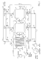
- rapid TSA is carried out using the apparatus of Figure 1, comprising three parallel adsorbers 10,12,14.
- Each shell and tube adsorber comprises 805 tubes 16 about 3.0' (0.91 m) in length, giving a heat exchange area of about 2200 ft 2 (204 m 2 ).
- the tubes are each packed with a layer of activated alumina and a layer of NaX zeolite.
- This apparatus is suitable for removal of water and carbon dioxide from compressed air (90 psia (620.6 kPa), 90 °F (32°C)).
- the adsorbent may be of a single type. Where alumina is used as either the single adsorbent or in combination with other adsorbent such as zeolite, it may be a modified alumina as described in US 5656064. Thus, the adsorbent may be formed by impregnating alumina with a basic solution having a pH of 9 or more.
- the beneficial effect of the treatment of the alumina with a basic solution may be due to the reaction of carbon dioxide with hydroxide ions in the basic environment of the alumina surface to form bicarbonate ions, although the applicant does not wish to be bound by this theory.
- the pH of the impregnating solution is at least 10, more preferably from 10 to 12. Best results have been obtained using an impregnating solution having a pH of about 11.
- the pH of the impregnating solution is related to the zero point charge (zpc) of the alumina according to the formula: pH ⁇ zpc-1.4 or more preferably by the formula: zpc+2 ⁇ pH ⁇ zpc-1.4
- the pH of the impregnating solution is related to the zero point charge of the alumina by the formula: zpc+1 ⁇ pH ⁇ zpc-1
- Said basic solution may suitably be a solution of an alkali metal or ammonium compound such as one selected from hydroxides, carbonates, bicarbonates, phosphates, and organic acid salts.
- Suitable basic compounds that may be employed include sodium, potassium or ammonium carbonate, hydroxide, phosphate bicarbonate, nitrate, formate, acetate, benzoate or citrate.
- the most preferred basic compound is potassium carbonate.
- the illustrated apparatus comprises a main air compressor 18 compressing feed air. Water is condensed out of the compressed feed air stream in a cooler 20 from which the compressed feed air passes to an inlet manifold 22.
- One of valves 24 passes feed air to the tube side inlet 26 of a first of the adsorbers (left-hand-most in the drawing)in which stage (a) of the process in ongoing. From the tube side outlet 28 of the adsorber, the purified air passes to an outlet manifold 30 via a valve 32 and so is led away as product gas at an outlet 34.
- a part of the product gas containing less than 10 ppm water and carbon dioxide is abstracted from the product stream at a pressure reduction valve 36 and is passed to a manifold 38 for passage via a valve 40 into the tube side outlet of the right-hand-most adsorber as regenerating gas for use in step (c) of the process.
- the effluent regenerating gas from the adsorber exits from the tube side inlet 26 of the adsorber to a manifold 42 via a valve 44 and passes up to a manifold 46 from which it passes via a valve 48 through the tube side outlet 28 of the middle adsorber as a regenerating gas for use in step (b) of the process.
- this regenerating gas can be heated to the desired regeneration temperature before entering the adsorber.
- the spent regenerating gas exits via the outlet 26 and is fed to waste via a valve 49 feeding a manifold 51.
- a heating fluid is circulated around a heating circuit 50 by a pump 52 feeding a heater 54 from which the fluid passes to the shell side inlet 56 of the middle adsorber via a valve 58 to supply the heat for step (b) of the process.
- the fluid exits via the shell side outlet 60 of the adsorber and passes back to the pump 52 via a valve 62.
- the direction of flow of the heating fluid can also be reverse of that shown in Figure 1.
- a cooling fluid (suitably cold water) is introduced at the shell side inlet of the right hand adsorber via a valve 64 and is discharged to waste from the shell side outlet of the adsorber via valve 66.
- the direction of the cooling fluid can be the reverse of that shown in Figure 1.
- each adsorber is moved on to the next step in the cycle.
- the compressed gas to be treated is passed through the packed tubes at near ambient temperature at a rate of 1 (0.0014) to 100 (0.14)lb moles/hr/ft 2 (Kg mol/sec/m 2 ) to produce an impurity-free product gas stream at feed pressure.
- the tubes are then depressurised counter-currently to near ambient pressure while heating them by counter-currently or co-currently flowing a heating fluid (gas or liquid) through the shell side of the adsorber.
- the heating step is continued until the feed-end of the adsorber tubes reach a pre-set temperature which is below the entrance temperature of the heating fluid.
- a small stream of the impurity-free product gas (or a gas from the cooling step described below containing a small amount of the impurities) is counter-currently passed at near ambient temperature through the tubes during the heating step in order to remove the desorbed impurities from inside the tubes.
- the gas may alternatively be pre-heated to the heating fluid temperature before entering the adsorber.
- the impurity-laden hot effluent gas is vented.
- the heating fluid leaving the shell side of the adsorber is reheated and recycled in a closed loop manner using a pump. After heating, the tubes are cooled by counter-currently flowing the cooling fluid (gas or liquid) through the shell side of the adsorber.
- a small portion of the product gas at near ambient temperature and pressure is passed counter-currently or co-currently through the tubes during the cooling step.
- the adsorber tubes are counter-currently pressurised to feed gas pressure using a portion of the clean product gas.
- the cooling fluid continues to flow through the shell side during the pressurisation step. The adsorber is now ready for a new cycle.
- Figure 2 is an example of the cycle times of various steps of the process. Table 1 compares the cycle times of Figure 2 with those of a conventional TSA process.
- the preferred embodiment of the invention has several advantages over the conventional TSA process.
- the preferred embodiment of the invention has a short cycle time of five to sixty, (more perferrably, ten to thirty) minutes that is significantly shorter than that of a conventional TSA process.
- this allows the adsorbers to be significantly smaller in size than conventional adsorbers. For example, for a cryogenic oxygen production plant having a capacity between 200 and 300 tons per day (181,436 Kg to 272,154 Kg per day) using the adsorption process of the present invention, there would be approximately a five to ten fold reduction in the adsorbent inventory needed for the plant.
- This embodiment of the invention shows a significant energy saving over the conventional TSA process.
- Another advantage of this embodiment of the invention is that a very small fraction of product gas, typically 3 to 10 %, is needed for regeneration because this gas is not supplying heat to the adsorbent. This means that the product yield is increased compared with conventional TSA.
- this embodiment of the present invention has the advantage that the cooling step is accelerated as well as the heating step.
- this embodiment of the present invention is much simpler, not involving the complex passage of feed and product gas through the tube and shell sides.
- the heating fluid may be chosen for optimum heating properties rather than being limited to the feed gas.
- the cooling step is carried out before feed gas enters the regenerated bed, allowing optimum adsorption throughout the adsorption step.
- the adsorbent is packed in beds in the tubes rather than being coated on the tube sides. The use of a simple packed bed eliminates channeling and costly production associated with structured or coated adsorbent concepts.
- This embodiment of the present invention removes carbon dioxide from the feed gas as well as moisture.
- the effluent impurity laden gas from the tube side can be further heated and used as part of the heating gas I the shell side by mixing it with the balance of the heating gas.
- Other options include the discharge without recirculation of the heating fluid, optionally with heat recovery therefrom, or the partial recirculation of the heating fluid, with a portion being replaced in each cycle.
- the heating fluid may in this instance particularly be feed gas or product gas and may be fed back into the feed gas or product gas stream on discharge.
Applications Claiming Priority (2)
| Application Number | Priority Date | Filing Date | Title |
|---|---|---|---|
| US09/939,876 US20030037672A1 (en) | 2001-08-27 | 2001-08-27 | Rapid thermal swing adsorption |
| US939876 | 2001-08-27 |
Publications (1)
| Publication Number | Publication Date |
|---|---|
| EP1291067A2 true EP1291067A2 (de) | 2003-03-12 |
Family
ID=25473875
Family Applications (1)
| Application Number | Title | Priority Date | Filing Date |
|---|---|---|---|
| EP02255859A Withdrawn EP1291067A2 (de) | 2001-08-27 | 2002-08-22 | Schnelle Wechseltemperaturabsorption |
Country Status (3)
| Country | Link |
|---|---|
| US (1) | US20030037672A1 (de) |
| EP (1) | EP1291067A2 (de) |
| JP (1) | JP2003175311A (de) |
Cited By (25)
| Publication number | Priority date | Publication date | Assignee | Title |
|---|---|---|---|---|
| WO2005000447A1 (fr) * | 2003-06-27 | 2005-01-06 | L'air Liquide, Societe Anonyme A Directoire Et Conseil De Surveillance Pour L'etude Et L'exploitation Des Procedes Georges Claude | Procede de prepurification d'air par cycle tsa accelere |
| WO2008106178A1 (en) * | 2007-02-27 | 2008-09-04 | Hunter Manufacturing Co. | Filtration heat transfer system |
| WO2008143964A1 (en) * | 2007-05-18 | 2008-11-27 | Exxonmobil Research And Engineering Company | Temperature swing adsorption of co2 from flue gas utilizing heat from compression |
| US7938886B2 (en) | 2007-05-18 | 2011-05-10 | Exxonmobil Research And Engineering Company | Process for removing a target gas from a mixture of gases by thermal swing adsorption |
| US7959720B2 (en) | 2007-05-18 | 2011-06-14 | Exxonmobil Research And Engineering Company | Low mesopore adsorbent contactors for use in swing adsorption processes |
| FR2969008A1 (fr) * | 2010-12-21 | 2012-06-22 | Air Liquide | Procede pour une epuration finale de biogaz |
| US8444750B2 (en) | 2007-05-18 | 2013-05-21 | Exxonmobil Research And Engineering Company | Removal of CO2, N2, or H2S from gas mixtures by swing adsorption with low mesoporosity adsorbent contactors |
| US8529662B2 (en) | 2007-05-18 | 2013-09-10 | Exxonmobil Research And Engineering Company | Removal of heavy hydrocarbons from gas mixtures containing heavy hydrocarbons and methane |
| US8529663B2 (en) | 2007-05-18 | 2013-09-10 | Exxonmobil Research And Engineering Company | Process for removing a target gas from a mixture of gases by swing adsorption |
| US8545602B2 (en) | 2007-05-18 | 2013-10-01 | Exxonmobil Research And Engineering Company | Removal of CO2, N2, and H2S from gas mixtures containing same |
| EP2740525A1 (de) * | 2012-12-10 | 2014-06-11 | Hitachi, Ltd. | Kohlendioxidtrennung aus einem Gas durch Temperaturwechseladsorption mittels organischer Adsobentien |
| EP2902087A1 (de) | 2014-02-04 | 2015-08-05 | Linde Aktiengesellschaft | Verfahren zur Abscheidung einer Komponente eines Gasgemischs unter Verwendung einer Temperaturwechseladsorption |
| US9222727B2 (en) | 2013-03-01 | 2015-12-29 | Praxair Technology, Inc. | Purification of argon through liquid phase cryogenic adsorption |
| US9457337B2 (en) | 2013-03-01 | 2016-10-04 | Praxair Technology, Inc. | Adsorbent composition for argon purification |
| WO2016200545A1 (en) | 2015-06-09 | 2016-12-15 | Praxair Technology, Inc | Helium enhanced heat transfer in adsorptive liquid argon purification process in a temperature swing adsorption process |
| WO2017012703A1 (de) | 2015-07-23 | 2017-01-26 | Linde Aktiengesellschaft | Adsorbens für ein temperaturwechseladsorptionsverfahren |
| US9644890B2 (en) | 2013-03-01 | 2017-05-09 | Praxair Technology, Inc. | Argon production method and apparatus |
| US10012437B2 (en) | 2015-07-31 | 2018-07-03 | Praxair Technology, Inc. | Method and apparatus for argon recovery in a cryogenic air separation unit integrated with a pressure swing adsorption system |
| US10012438B2 (en) | 2015-07-31 | 2018-07-03 | Praxair Technology, Inc. | Method and apparatus for argon recovery in a cryogenic air separation unit integrated with a pressure swing adsorption system |
| US10018413B2 (en) | 2015-07-31 | 2018-07-10 | Praxair Technology, Inc. | Method and apparatus for increasing argon recovery in a cryogenic air separation unit integrated with a pressure swing adsorption system |
| US10066871B2 (en) | 2015-07-31 | 2018-09-04 | Praxair Technology, Inc. | Method and apparatus for argon rejection and recovery |
| EP3520881A1 (de) * | 2018-01-31 | 2019-08-07 | Linde Aktiengesellschaft | Verfahren zur trennung eines gasgemischstroms mittels temperaturwechseladsorption und temperaturwechseladsorptionsanlage |
| US11262125B2 (en) | 2018-01-02 | 2022-03-01 | Praxair Technology, Inc. | System and method for flexible recovery of argon from a cryogenic air separation unit |
| RU2791134C2 (ru) * | 2018-01-31 | 2023-03-02 | Линде Гмбх | Способ разделения потока газовой смеси с использованием адсорбции при переменной температуре и установка для адсорбции при переменной температуре |
| EP4309764A1 (de) * | 2022-07-21 | 2024-01-24 | Linde GmbH | Verfahren und vorrichtung zum entfernen von komponenten aus einem speisegasgemisch |
Families Citing this family (61)
| Publication number | Priority date | Publication date | Assignee | Title |
|---|---|---|---|---|
| US6942719B2 (en) * | 2003-06-30 | 2005-09-13 | The Boeing Company | Methods and systems for pressure swing regeneration for hydrogen generation |
| US7115152B2 (en) * | 2004-01-12 | 2006-10-03 | Friday David K | Four bed regenerable filter system |
| JP4608444B2 (ja) * | 2006-02-06 | 2011-01-12 | 日本エア・リキード株式会社 | 圧縮空気製造方法および製造装置 |
| US7744677B2 (en) * | 2007-05-25 | 2010-06-29 | Prometheus Technologies, Llc | Systems and methods for processing methane and other gases |
| JP4848335B2 (ja) * | 2007-09-19 | 2011-12-28 | 月島環境エンジニアリング株式会社 | ガス処理方法 |
| US8137439B2 (en) * | 2008-09-03 | 2012-03-20 | Air Liquide Process & Construction, Inc. | Process and apparatus for CO2 recovery from flue gas with thermocompression |
| US8425674B2 (en) | 2008-10-24 | 2013-04-23 | Exxonmobil Research And Engineering Company | System using unutilized heat for cooling and/or power generation |
| US8226746B2 (en) * | 2008-12-17 | 2012-07-24 | Uop Llc | Indirectly heated temperature controlled adsorber for sorbate recovery |
| US8227648B2 (en) * | 2008-12-17 | 2012-07-24 | Uop Llc | Combined temperature controlled water adsorption and two stage heat pump process for fuel ethanol dehydration |
| FR2952553B1 (fr) * | 2009-11-19 | 2012-06-01 | Air Liquide | Procede de purification d'un flux gazeux mettant en oeuvre un contacteur a passages paralleles presentant une conservation de ses performances |
| JP5534865B2 (ja) * | 2010-02-27 | 2014-07-02 | Jfeスチール株式会社 | 圧力スイング吸着法によるガス分離方法及びガス分離装置 |
| US20110219802A1 (en) * | 2010-03-09 | 2011-09-15 | Exxonmobil Research And Engineering Company | Sorption systems having improved cycle times |
| US8157892B2 (en) | 2010-05-17 | 2012-04-17 | Enverid Systems, Inc. | Method and system for improved-efficiency air-conditioning |
| EP2407228B1 (de) * | 2010-07-14 | 2016-09-07 | General Electric Technology GmbH | Gasreinigungseinheit und verfahren zum reinigen von gas |
| US20120152116A1 (en) | 2010-12-16 | 2012-06-21 | Prometheus Technologies, Llc | Rotary fluid processing systems and associated methods |
| EP2497563A1 (de) | 2011-03-08 | 2012-09-12 | Alstom Technology Ltd | System und Verfahren zur Regenerierung von Trockenmitteln mit niedriger NOx-Emission |
| US8574348B2 (en) * | 2011-03-31 | 2013-11-05 | Uop Llc | Process for purifying a gas in a temperature swing adsorption unit |
| US20140047978A1 (en) * | 2011-03-31 | 2014-02-20 | Uop Llc | Process for purifying a gas in a temperature swing adsorption unit |
| JP5864281B2 (ja) * | 2012-01-20 | 2016-02-17 | 株式会社日立製作所 | Co2分離回収装置 |
| EP2638949A1 (de) * | 2012-03-13 | 2013-09-18 | Ammonia Casale S.A. | Verfahren zum Entfernen von Kohlendioxid aus einem Gasstrom |
| JP5829168B2 (ja) * | 2012-03-30 | 2015-12-09 | 株式会社日立製作所 | 二酸化炭素回収システム及びこれを用いた二酸化炭素回収方法 |
| KR101221088B1 (ko) * | 2012-03-30 | 2013-01-11 | (주)제니스텍 | 광범위 정제용 초저온 냉각 트랩장치 |
| KR101359569B1 (ko) * | 2012-05-18 | 2014-02-12 | 고등기술연구원연구조합 | Voc 응축 모듈 |
| CN108096991A (zh) | 2012-05-22 | 2018-06-01 | 恩沃德系统公司 | 对室内空气的洗涤的吸附剂的高效利用 |
| WO2014015138A2 (en) | 2012-07-18 | 2014-01-23 | Enverid Systems, Inc. | Systems and methods for regenerating adsorbents for indoor air scrubbing |
| US9399187B2 (en) | 2012-09-24 | 2016-07-26 | Enverid Systems, Inc. | Air handling system with integrated air treatment |
| CN104797323B (zh) | 2012-11-15 | 2017-11-14 | 恩沃德系统公司 | 适用于减少室内空气中的有害气体的方法和系统 |
| WO2014091590A1 (ja) * | 2012-12-13 | 2014-06-19 | 株式会社日立製作所 | Co2回収装置及びその運転方法 |
| US8936669B2 (en) * | 2013-05-06 | 2015-01-20 | Uop Llc | Temperature swing adsorption systems and methods for purifying fluids using the same |
| US9919257B2 (en) * | 2013-09-17 | 2018-03-20 | Enverid Systems, Inc. | Systems and methods for efficient heating of sorbents in an indoor air scrubber |
| US9314731B2 (en) | 2013-11-20 | 2016-04-19 | L'Air Liquide, Société Anonyme pour l'Etude et l'Exploitation des Procédés Georges Claude | RTSA method using adsorbent structure for CO2 capture from low pressure and low concentration sources |
| US9308486B2 (en) * | 2013-11-20 | 2016-04-12 | L'Air Liquide, Société Anonyme pour l'Etude et l'Exploitation des Procédés Georges Claude | Method of using a structured adsorbent bed for capture of CO2 from low pressure and low pressure concentration sources |
| US20150375158A1 (en) * | 2013-11-26 | 2015-12-31 | Martin Lang | Increased onstream time for cryogenic separation processes |
| KR101480654B1 (ko) * | 2013-12-24 | 2015-01-13 | 연세대학교 산학협력단 | 다중관형 이산화탄소 포집장치 |
| US9517983B2 (en) * | 2014-07-16 | 2016-12-13 | Basf Corporation | Regeneration loop clean-up |
| US20180147526A1 (en) | 2015-05-11 | 2018-05-31 | Enverid Systems, Inc. | Method and system for reduction of unwanted gases in indoor air |
| WO2017035254A1 (en) | 2015-08-24 | 2017-03-02 | Enverid Systems, Inc. | Scrubber for hvac system |
| US10105637B2 (en) * | 2015-09-25 | 2018-10-23 | Praxair Technology, Inc. | Adsorbent regeneration method |
| US9827602B2 (en) | 2015-09-28 | 2017-11-28 | Tesla, Inc. | Closed-loop thermal servicing of solvent-refining columns |
| EP3216512A1 (de) * | 2016-03-08 | 2017-09-13 | Casale SA | Temperaturwechseladsorptionsverfahren |
| EP3216511A1 (de) * | 2016-03-08 | 2017-09-13 | Casale SA | Temperaturwechseladsorptionsverfahren |
| JP2019512662A (ja) * | 2016-03-31 | 2019-05-16 | インベンティーズ サーマル テクノロジーズ インコーポレイテッド | 温度変動吸着式ガス分離 |
| US11207633B2 (en) | 2016-04-19 | 2021-12-28 | Enverid Systems, Inc. | Systems and methods for closed-loop heating and regeneration of sorbents |
| US9687778B1 (en) * | 2016-04-21 | 2017-06-27 | The Fischer Group, Inc. | Systems and methods for drying a compressed gas |
| EP3260185A1 (de) * | 2016-06-21 | 2017-12-27 | Donaldson Filtration Deutschland GmbH | Vorrichtung zur temperaturwechsel-adsorption und verfahren zur temperaturwechsel-adsorption für die reinigung von gasen |
| CN109952140A (zh) | 2016-11-10 | 2019-06-28 | 恩弗里德系统公司 | 低噪声、天花板安装的室内空气洗涤器 |
| EP3338875A1 (de) | 2016-12-22 | 2018-06-27 | Solvay SA | Gasextraktionsverfahren mit einem verbesserten temperaturwechseladsorptionsverfahren und vorrichtung zur durchführung davon |
| JP7333753B2 (ja) | 2017-01-31 | 2023-08-25 | カルゴン カーボン コーポレーション | 吸着装置 |
| EP3449996A1 (de) * | 2017-08-28 | 2019-03-06 | Casale Sa | Temperaturwechseladsorptionsverfahren |
| WO2019238488A1 (en) * | 2018-06-14 | 2019-12-19 | Climeworks Ag | Method and device for adsorption/desorption of carbon dioxide from gas streams with heat recovery unit |
| US11697580B2 (en) * | 2018-08-01 | 2023-07-11 | Calgon Carbon Corporation | Apparatus for hydrocarbon vapor recovery |
| US11703016B2 (en) | 2018-08-02 | 2023-07-18 | Calgon Carbon Corporation | Sorbent devices |
| WO2020028839A1 (en) | 2018-08-02 | 2020-02-06 | Calgon Carbon Corporation | Sorbent devices |
| DE102018006960A1 (de) | 2018-09-03 | 2020-03-05 | Linde Aktiengesellschaft | Verfahren zum Betreiben einer Temperaturwechseladsorptionsanlage und Temperaturwechseladsorptionsanlage |
| FR3086373B1 (fr) * | 2018-09-20 | 2020-12-11 | Air Liquide | Installation et procede d'epuration et de liquefaction de gaz naturel |
| EP3646935A1 (de) | 2018-10-30 | 2020-05-06 | Ecole Polytechnique Federale de Lausanne (EPFL) | System zur co2-abscheidung aus verbrennungsmotoren |
| US11052347B2 (en) | 2018-12-21 | 2021-07-06 | Entegris, Inc. | Bulk process gas purification systems |
| CN109966860A (zh) * | 2019-04-16 | 2019-07-05 | 北京科技大学 | 一种多床变温吸附气体净化系统及工艺 |
| JP7356885B2 (ja) * | 2019-12-06 | 2023-10-05 | 株式会社豊田中央研究所 | ガス分離装置およびガス分離装置の制御方法 |
| CN111013319A (zh) * | 2019-12-24 | 2020-04-17 | 浙江大学 | 一种用于空分纯化装置的分子筛吸附器及该装置和方法 |
| CN111013321A (zh) * | 2019-12-24 | 2020-04-17 | 浙江大学 | 一种可回收潜热的三吸附器空分纯化装置及其方法 |
-
2001
- 2001-08-27 US US09/939,876 patent/US20030037672A1/en not_active Abandoned
-
2002
- 2002-08-22 EP EP02255859A patent/EP1291067A2/de not_active Withdrawn
- 2002-08-26 JP JP2002245342A patent/JP2003175311A/ja active Pending
Cited By (39)
| Publication number | Priority date | Publication date | Assignee | Title |
|---|---|---|---|---|
| WO2005000447A1 (fr) * | 2003-06-27 | 2005-01-06 | L'air Liquide, Societe Anonyme A Directoire Et Conseil De Surveillance Pour L'etude Et L'exploitation Des Procedes Georges Claude | Procede de prepurification d'air par cycle tsa accelere |
| WO2008106178A1 (en) * | 2007-02-27 | 2008-09-04 | Hunter Manufacturing Co. | Filtration heat transfer system |
| US7959720B2 (en) | 2007-05-18 | 2011-06-14 | Exxonmobil Research And Engineering Company | Low mesopore adsorbent contactors for use in swing adsorption processes |
| US7731782B2 (en) | 2007-05-18 | 2010-06-08 | Exxonmobil Research And Engineering Company | Temperature swing adsorption of CO2 from flue gas utilizing heat from compression |
| US7938886B2 (en) | 2007-05-18 | 2011-05-10 | Exxonmobil Research And Engineering Company | Process for removing a target gas from a mixture of gases by thermal swing adsorption |
| US7947120B2 (en) | 2007-05-18 | 2011-05-24 | Exxonmobil Research And Engineering Company | Temperature swing adsorption of CO2 from flue gas using a parallel channel contractor |
| US8529664B2 (en) | 2007-05-18 | 2013-09-10 | Exxonmobil Research And Engineering Company | Removal of a target gas from a mixture of gases by swing adsorption with use of a turboexpander |
| EA015731B1 (ru) * | 2007-05-18 | 2011-10-31 | Эксонмобил Рисерч Энд Инджиниринг Компани | Способ удаления coиз потока газовой смеси |
| WO2008143964A1 (en) * | 2007-05-18 | 2008-11-27 | Exxonmobil Research And Engineering Company | Temperature swing adsorption of co2 from flue gas utilizing heat from compression |
| US8545602B2 (en) | 2007-05-18 | 2013-10-01 | Exxonmobil Research And Engineering Company | Removal of CO2, N2, and H2S from gas mixtures containing same |
| US8444750B2 (en) | 2007-05-18 | 2013-05-21 | Exxonmobil Research And Engineering Company | Removal of CO2, N2, or H2S from gas mixtures by swing adsorption with low mesoporosity adsorbent contactors |
| US8529662B2 (en) | 2007-05-18 | 2013-09-10 | Exxonmobil Research And Engineering Company | Removal of heavy hydrocarbons from gas mixtures containing heavy hydrocarbons and methane |
| US8529663B2 (en) | 2007-05-18 | 2013-09-10 | Exxonmobil Research And Engineering Company | Process for removing a target gas from a mixture of gases by swing adsorption |
| US9272963B2 (en) | 2010-12-21 | 2016-03-01 | L'Air Liquide, Société Anonyme pour l'Etude et l'Exploitation des Procédés Georges Claude | Final biogas purification process |
| WO2012085128A1 (fr) * | 2010-12-21 | 2012-06-28 | L'air Liquide, Societe Anonyme Pour L'etude Et L'exploitation Des Procedes Georges Claude | Procédé d'épuration finale de biogaz |
| FR2969008A1 (fr) * | 2010-12-21 | 2012-06-22 | Air Liquide | Procede pour une epuration finale de biogaz |
| EP2740525A1 (de) * | 2012-12-10 | 2014-06-11 | Hitachi, Ltd. | Kohlendioxidtrennung aus einem Gas durch Temperaturwechseladsorption mittels organischer Adsobentien |
| US9222727B2 (en) | 2013-03-01 | 2015-12-29 | Praxair Technology, Inc. | Purification of argon through liquid phase cryogenic adsorption |
| US9457337B2 (en) | 2013-03-01 | 2016-10-04 | Praxair Technology, Inc. | Adsorbent composition for argon purification |
| US9644890B2 (en) | 2013-03-01 | 2017-05-09 | Praxair Technology, Inc. | Argon production method and apparatus |
| US9759482B2 (en) | 2013-03-01 | 2017-09-12 | Praxair Technology, Inc. | Argon production method and apparatus |
| US9772139B2 (en) | 2013-03-01 | 2017-09-26 | Praxair Technology, Inc. | Purification of argon through liquid phase cryogenic adsorption |
| EP2902087A1 (de) | 2014-02-04 | 2015-08-05 | Linde Aktiengesellschaft | Verfahren zur Abscheidung einer Komponente eines Gasgemischs unter Verwendung einer Temperaturwechseladsorption |
| WO2016200545A1 (en) | 2015-06-09 | 2016-12-15 | Praxair Technology, Inc | Helium enhanced heat transfer in adsorptive liquid argon purification process in a temperature swing adsorption process |
| US9676629B2 (en) | 2015-06-09 | 2017-06-13 | Praxair Technology, Inc. | Helium enhanced heat transfer in adsorptive liquid or gas phase argon purification processes |
| WO2017012703A1 (de) | 2015-07-23 | 2017-01-26 | Linde Aktiengesellschaft | Adsorbens für ein temperaturwechseladsorptionsverfahren |
| US10012437B2 (en) | 2015-07-31 | 2018-07-03 | Praxair Technology, Inc. | Method and apparatus for argon recovery in a cryogenic air separation unit integrated with a pressure swing adsorption system |
| US10012438B2 (en) | 2015-07-31 | 2018-07-03 | Praxair Technology, Inc. | Method and apparatus for argon recovery in a cryogenic air separation unit integrated with a pressure swing adsorption system |
| US10018413B2 (en) | 2015-07-31 | 2018-07-10 | Praxair Technology, Inc. | Method and apparatus for increasing argon recovery in a cryogenic air separation unit integrated with a pressure swing adsorption system |
| US10024596B2 (en) | 2015-07-31 | 2018-07-17 | Praxair Technology, Inc. | Method and apparatus for argon recovery in a cryogenic air separation unit integrated with a pressure swing adsorption system |
| US10066871B2 (en) | 2015-07-31 | 2018-09-04 | Praxair Technology, Inc. | Method and apparatus for argon rejection and recovery |
| US10145609B2 (en) | 2015-07-31 | 2018-12-04 | Praxair Technology, Inc. | Method ad apparatus for argon recovery in a cryogenic air separation unit integrated with a pressure swing adsorption |
| US11262125B2 (en) | 2018-01-02 | 2022-03-01 | Praxair Technology, Inc. | System and method for flexible recovery of argon from a cryogenic air separation unit |
| EP3520881A1 (de) * | 2018-01-31 | 2019-08-07 | Linde Aktiengesellschaft | Verfahren zur trennung eines gasgemischstroms mittels temperaturwechseladsorption und temperaturwechseladsorptionsanlage |
| WO2019149445A1 (de) * | 2018-01-31 | 2019-08-08 | Linde Aktiengesellschaft | Verfahren zur trennung eines gasgemischstroms mittels temperaturwechseladsorption und temperaturwechseladsorptionsanlage |
| RU2791134C2 (ru) * | 2018-01-31 | 2023-03-02 | Линде Гмбх | Способ разделения потока газовой смеси с использованием адсорбции при переменной температуре и установка для адсорбции при переменной температуре |
| US11772036B2 (en) | 2018-01-31 | 2023-10-03 | Linde Gmbh | Method for separating a gas mixture flow using temperature-change adsorption, and temperature-change adsorption plant |
| EP4309764A1 (de) * | 2022-07-21 | 2024-01-24 | Linde GmbH | Verfahren und vorrichtung zum entfernen von komponenten aus einem speisegasgemisch |
| WO2024017503A1 (en) * | 2022-07-21 | 2024-01-25 | Linde Gmbh | Process and apparatus for removing components from a feed gas mixture |
Also Published As
| Publication number | Publication date |
|---|---|
| US20030037672A1 (en) | 2003-02-27 |
| JP2003175311A (ja) | 2003-06-24 |
Similar Documents
| Publication | Publication Date | Title |
|---|---|---|
| EP1291067A2 (de) | Schnelle Wechseltemperaturabsorption | |
| KR100192697B1 (ko) | 고체 흡착제를 사용한 기체 정제법 | |
| US4784672A (en) | Regeneration of adsorbents | |
| US7294172B2 (en) | Helium recovery | |
| US8216344B2 (en) | Purifying carbon dioxide using activated carbon | |
| US4711645A (en) | Removal of water and carbon dioxide from atmospheric air | |
| CA2209441C (en) | Multi-thermal pulse psa system | |
| EP1811011A1 (de) | Rückgewinnung von Methan von einem Deponiegas | |
| AU2013231676B2 (en) | Process for removing carbon dioxide from a gas stream | |
| JP2012503593A (ja) | 二酸化炭素を精製し硫酸と硝酸を製造する多段方法 | |
| US20120009114A1 (en) | Gas pressurized separation column and process to generate a high pressure product gas | |
| US9919259B2 (en) | Gas pressurized separation column and process to generate a high pressure product gas | |
| JP2000317244A (ja) | ガス精製方法及び装置 | |
| EP2364766B1 (de) | Verfahren zur Entfernung von Feuchtigkeit in einem Gasstrom | |
| CN108367230A (zh) | 变温吸附方法 | |
| CN111093800B (zh) | 变温吸附方法 | |
| CN111093801B (zh) | 变温吸附方法 | |
| JP3841792B2 (ja) | 空気分離装置における前処理方法およびそれに用いる装置 | |
| RU2791134C2 (ru) | Способ разделения потока газовой смеси с использованием адсорбции при переменной температуре и установка для адсорбции при переменной температуре | |
| JPH11319458A (ja) | 空気分離装置における前処理装置 | |
| SU929208A1 (ru) | Способ регенерации адсорбента | |
| JPH0132435B2 (de) |
Legal Events
| Date | Code | Title | Description |
|---|---|---|---|
| PUAI | Public reference made under article 153(3) epc to a published international application that has entered the european phase |
Free format text: ORIGINAL CODE: 0009012 |
|
| STAA | Information on the status of an ep patent application or granted ep patent |
Free format text: STATUS: THE APPLICATION HAS BEEN WITHDRAWN |
|
| AK | Designated contracting states |
Kind code of ref document: A2 Designated state(s): AT BE BG CH CY CZ DE DK EE ES FI FR GB GR IE IT LI LU MC NL PT SE SK TR Designated state(s): AT BE BG CH CY CZ DE DK EE ES FI FR GB GR IE IT LI LU MC NL PT SE SK TR |
|
| AX | Request for extension of the european patent |
Extension state: AL LT LV MK RO SI |
|
| 18W | Application withdrawn |
Effective date: 20030127 |