EP1289719B1 - Device for slicing foodstuffs - Google Patents
Device for slicing foodstuffs Download PDFInfo
- Publication number
- EP1289719B1 EP1289719B1 EP01933813A EP01933813A EP1289719B1 EP 1289719 B1 EP1289719 B1 EP 1289719B1 EP 01933813 A EP01933813 A EP 01933813A EP 01933813 A EP01933813 A EP 01933813A EP 1289719 B1 EP1289719 B1 EP 1289719B1
- Authority
- EP
- European Patent Office
- Prior art keywords
- cutting
- edge part
- cutting edge
- blade
- accordance
- Prior art date
- Legal status (The legal status is an assumption and is not a legal conclusion. Google has not performed a legal analysis and makes no representation as to the accuracy of the status listed.)
- Expired - Lifetime
Links
Images
Classifications
-
- B—PERFORMING OPERATIONS; TRANSPORTING
- B26—HAND CUTTING TOOLS; CUTTING; SEVERING
- B26D—CUTTING; DETAILS COMMON TO MACHINES FOR PERFORATING, PUNCHING, CUTTING-OUT, STAMPING-OUT OR SEVERING
- B26D7/00—Details of apparatus for cutting, cutting-out, stamping-out, punching, perforating, or severing by means other than cutting
- B26D7/01—Means for holding or positioning work
-
- Y—GENERAL TAGGING OF NEW TECHNOLOGICAL DEVELOPMENTS; GENERAL TAGGING OF CROSS-SECTIONAL TECHNOLOGIES SPANNING OVER SEVERAL SECTIONS OF THE IPC; TECHNICAL SUBJECTS COVERED BY FORMER USPC CROSS-REFERENCE ART COLLECTIONS [XRACs] AND DIGESTS
- Y10—TECHNICAL SUBJECTS COVERED BY FORMER USPC
- Y10T—TECHNICAL SUBJECTS COVERED BY FORMER US CLASSIFICATION
- Y10T83/00—Cutting
- Y10T83/444—Tool engages work during dwell of intermittent workfeed
- Y10T83/4539—Means to change tool position, or length or datum position of work- or tool-feed increment
- Y10T83/4559—With means to vary magnitude or base position of tool stroke
-
- Y—GENERAL TAGGING OF NEW TECHNOLOGICAL DEVELOPMENTS; GENERAL TAGGING OF CROSS-SECTIONAL TECHNOLOGIES SPANNING OVER SEVERAL SECTIONS OF THE IPC; TECHNICAL SUBJECTS COVERED BY FORMER USPC CROSS-REFERENCE ART COLLECTIONS [XRACs] AND DIGESTS
- Y10—TECHNICAL SUBJECTS COVERED BY FORMER USPC
- Y10T—TECHNICAL SUBJECTS COVERED BY FORMER US CLASSIFICATION
- Y10T83/00—Cutting
- Y10T83/647—With means to convey work relative to tool station
-
- Y—GENERAL TAGGING OF NEW TECHNOLOGICAL DEVELOPMENTS; GENERAL TAGGING OF CROSS-SECTIONAL TECHNOLOGIES SPANNING OVER SEVERAL SECTIONS OF THE IPC; TECHNICAL SUBJECTS COVERED BY FORMER USPC CROSS-REFERENCE ART COLLECTIONS [XRACs] AND DIGESTS
- Y10—TECHNICAL SUBJECTS COVERED BY FORMER USPC
- Y10T—TECHNICAL SUBJECTS COVERED BY FORMER US CLASSIFICATION
- Y10T83/00—Cutting
- Y10T83/768—Rotatable disc tool pair or tool and carrier
- Y10T83/7684—With means to support work relative to tool[s]
- Y10T83/7701—Supporting surface and tool axis angularly related
- Y10T83/7705—Adjustable angular relationship
Definitions
- the invention relates to a device for slicing food products according to the preamble of claims 1 and 7.
- a device for slicing food products is known from US 5 241 887.
- slicers commonly referred to as slicers and will work at very high cutting speeds even at these very high working speeds and in particular even more difficult to cut products clean and perfect Cuts required.
- the quality or accuracy in particular has an influence on the cut quality between the contact surface for the product being fed and both rotating around its own axis and planetary circumferential cutting knife trained cutting gap.
- the quality or accuracy of the cutting gap is impaired especially due to depth deviations of the cutting knife, which are due to the manufacturing process are and can lead to deviations result with respect to the target cutting gap size, the target cutting gap size ideally is zero.
- the object of the present invention is a device of the beginning mentioned type in such a way that the cut quality deteriorating Deviations from the target cutting gap can be switched off and therefore independent of the knife used and also independent an optimal and constant of the respective operating conditions Cutting gap can be guaranteed.
- the cutting edge part that is together forms the cutting gap with the cutting knife each time the knife is passed minimally displaced from its basic position, the size of this Displacement is in the range of a few tenths of a millimeter.
- the cutting edge part is in the entry area of the cutting knife with at least one guide surface equipped, which ensures that the cutting knife on a slightly inclined Surface section of the cutting edge part hits, causing annoying Friction and unwanted wear can be practically eliminated.
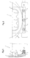
- the product feed unit arranged in a machine housing 10 1 comprises a product support surface 2, along which the one to be cut in each case Product in the direction of between the knife 4 and the front end of the product support surface 2 formed cutting gap is transported.
- the product support surface has 2 three shots arranged side by side for three products to be cut simultaneously, as shown in FIG is.
- the front end of the product support surface 2 is - as shown in Fig. 1 - of a cutting edge part 3, which is preferably made of a suitable plastic material exists.
- the cutting edge part 3 is vertical in the product feed device 1 displaceable to the cutting plane or to the orbit of the cutting knife 4 stored, for which the product feed device 1 suitable guide surfaces 7 has. 2 shows two flight circles 9, for example different cutting knife 4 shown.
- the displaceability of the cutting edge part 3 in the direction of the cutting plane is limited by a stop 6, which ensures that the Cutting edge part 3 a maximum of only a few tenths of a millimeter into the Cutting path of the knife 4 can protrude.
- the cutting edge part 3 is biased by at least one spring element 5th
- the cutting edge part 3 in the area of the knife entry with a slightly inclined guide surface 8 equipped.
- a slightly inclined, short guide surface is sufficient 8 the uppermost point with respect to the end face of the cutting edge part for example, is set back by about 1 mm and then goes into a vertical course.
- the slight bevel required to create the guide surface mentioned a partial area of the end face of the cutting edge part 2 does not degrade the quality of the cut, but it does safe operation of the entire device with simultaneous guarantee an absolute constancy of the cutting gap, because the The cutting gap is caused by the interaction of the Cutting knife movable with the perpendicular to the cutting knife level stored cutting edge part formed and practically at zero value held.
- an actively controlled Cutting edge part may be provided.
- the control of such Cutting edge part takes place depending on the movement of the knife and possibly also depending on knife characteristics.
- Actuators for moving the cutting edge part come for example piezoelectric elements or other actuators into consideration, which are sufficiently fast and short-term movements of the Cutting edge part over short distances, for example in the millimeter range, guarantee.
Landscapes
- Life Sciences & Earth Sciences (AREA)
- Forests & Forestry (AREA)
- Engineering & Computer Science (AREA)
- Mechanical Engineering (AREA)
- Nonmetal Cutting Devices (AREA)
- Meat, Egg Or Seafood Products (AREA)
- Control And Other Processes For Unpacking Of Materials (AREA)
- Perforating, Stamping-Out Or Severing By Means Other Than Cutting (AREA)
- Mechanical Treatment Of Semiconductor (AREA)
- Details Of Cutting Devices (AREA)
Abstract
Description
Die Erfindung betrifft eine Vorrichtung zum Aufschneiden von Lebensmittelprodukten
gemäß dem Oberbegriff der Ansprüchen 1 und 7. Eine Solche Vorrichtung
ist aus US 5 241 887 bekannt.The invention relates to a device for slicing food products
according to the preamble of
Von derartigen Vorrichtungen, die üblicherweise auch als Slicer bezeichnet werden und mit sehr hohen Schnittgeschwindigkeiten arbeiten, werden auch bei diesen sehr hohen Arbeitsgeschwindigkeiten und insbesondere auch schwieriger aufzuschneidenden Produkten saubere und einwandfreie Schnitte gefordert.Of such devices, commonly referred to as slicers and will work at very high cutting speeds even at these very high working speeds and in particular even more difficult to cut products clean and perfect Cuts required.
Einfluß auf die Schnittqualität hat insbesondere die Güte bzw. Genauigkeit des zwischen der Auflagefläche für das jeweils zugeführte Produkt und dem sowohl um die eigene Achse rotierenden als auch planetarisch umlaufenden Schneidmesser ausgebildeten Schneidspalts.The quality or accuracy in particular has an influence on the cut quality between the contact surface for the product being fed and both rotating around its own axis and planetary circumferential cutting knife trained cutting gap.
Beeinträchtigt wird in der Praxis die Güte bzw. Genauigkeit des Schneidspalts vor allem durch Tiefenabweichungen des Schneidmessers, die fertigungsbedingt sind und durchaus dazu führen können, daß sich Abweichungen bezüglich der Soll-Schneidspaltgröße ergeben, wobei die Soll-Schneidspaltgröße im Idealfall Null beträgt. In practice, the quality or accuracy of the cutting gap is impaired especially due to depth deviations of the cutting knife, which are due to the manufacturing process are and can lead to deviations result with respect to the target cutting gap size, the target cutting gap size ideally is zero.
Aufgabe der vorliegenden Erfindung ist es, eine Vorrichtung der eingangs genannten Art in der Weise auszubilden, daß die Schnittqualität verschlechternde Abweichungen vom Soll-Schneidspalt ausgeschaltet werden und somit unabhängig vom jeweils verwendeten Messer und auch unabhängig von den jeweiligen Betriebsbedingungen ein optimaler und konstanter Schneidspalt gewährleistet werden kann.The object of the present invention is a device of the beginning mentioned type in such a way that the cut quality deteriorating Deviations from the target cutting gap can be switched off and therefore independent of the knife used and also independent an optimal and constant of the respective operating conditions Cutting gap can be guaranteed.
Gemäß der Erfindung wird diese Aufgabe durch die Merkmale der Ansprüche 1 oder 7 gelöst.According to the invention, this object is achieved by the features of
Durch diese Ausgestaltung wird das Schneidkantenteil, das zusammen mit dem Schneidmesser den Schneidspalt bildet, bei jedem Messerdurchgang minimal aus seiner Grundposition verdrängt, wobei die Größe dieser Verdrängung im Bereich weniger Zehntelmillimeter gelegen ist.With this configuration, the cutting edge part that is together forms the cutting gap with the cutting knife, each time the knife is passed minimally displaced from its basic position, the size of this Displacement is in the range of a few tenths of a millimeter.
Um dabei ein problemfreies Zusammenwirken zwischen Schneidmesser und Schneidkantenteil sicherzustellen, ist das Schneidkantenteil im Eintrittsbereich des Schneidmessers mit zumindest einer Führungsfläche ausgestattet, die sicherstellt, daß das Schneidmesser auf einen leicht geneigten Flächenabschnitt des Schneidkantenteils trifft, wodurch störende Reibung und unerwünschter Verschleiß praktisch ausgeschaltet werden. To ensure a problem-free interaction between the cutting knife and to ensure the cutting edge part, the cutting edge part is in the entry area of the cutting knife with at least one guide surface equipped, which ensures that the cutting knife on a slightly inclined Surface section of the cutting edge part hits, causing annoying Friction and unwanted wear can be practically eliminated.
Weitere vorteilhafte Ausgestaltungen und Merkmale der Erfindung sind in den Unteransprüchen angegeben und werden auch bei der Beschreibung eines Ausführungsbeispiels unter Bezugnahme auf die Zeichnung erläutert. In der Zeichnung zeigt:
- Fig. 1
- in schematischer Weise eine mit einem Schneidmesser zusammenwirkende Produktzuführungseinheit in teilweise geschnittener Seitenansicht, und
- Fig. 2
- eine Vorderansicht der Anordnung nach Fig. 1.
- Fig. 1
- schematically a product feed unit cooperating with a cutting knife in a partially sectioned side view, and
- Fig. 2
- 2 shows a front view of the arrangement according to FIG. 1.
Die in einem Maschinengehäuse 10 angeordnete Produktzuführungseinheit
1 umfaßt eine Produktauflagefläche 2, längs der das jeweils aufzuschneidende
Produkt in Richtung des zwischen dem Messer 4 und dem
vorderen Ende der Produktauflagefläche 2 ausgebildeten Schneidspaltes
transportiert wird. Im dargestellten Ausführungsbeispiel weist die Produktauflagefläche
2 drei nebeneinanderliegend angeordnete Aufnahmen
für drei gleichzeitig zu schneidende Produkte auf, wie dies in Fig. 2 gezeigt
ist.The product feed unit arranged in a
Das vordere Ende der Produktauflagefläche 2 wird - wie in Fig. 1 gezeigt -
von einem Schneidkantenteil 3, das vorzugsweise aus geeignetem Kunststoffmaterial
besteht, gebildet.The front end of the
Das Schneidkantenteil 3 ist in der Produktzuführungseinrichtung 1 senkrecht
zur Schneidebene bzw. zur Umlaufbahn des Schneidmessers 4 verschiebbar
gelagert, wozu die Produktzuführeinrichtung 1 geeignete Führungsflächen
7 aufweist. In Fig. 2 sind beispielsweise zwei Flugkreise 9
unterschiedlicher Schneidmesser 4 dargestellt.The cutting edge part 3 is vertical in the
Die Verschiebbarkeit des Schneidkantenteils 3 in Richtung der Schneidebene
ist durch einen Anschlag 6 begrenzt, der sicherstellt, daß das
Schneidkantenteil 3 maximal nur wenige Zehntelmillimeter in die
Schneidbahn des Messers 4 ragen kann. In Richtung der Schneidebene ist
das Schneidkantenteil 3 vorgespannt, und zwar durch mindestens ein Federelement
5.The displaceability of the cutting edge part 3 in the direction of the cutting plane
is limited by a
Um sicherzustellen, daß das Schneidkantenteil 3 bei jedem Schnitt, d.h. bei jedem Zusammenwirken mit dem Schneidmesser 4 geringfügig gegen die Federvorspannung verdrängt werden kann, ist das Schneidkantenteil 3 im Bereich des Messereintritts mit einer leicht geneigten Führungsfläche 8 ausgestattet. In der Praxis genügt eine leicht geneigte, kurze Führungsfläche 8, deren oberster Punkt bezüglich der Stirnfläche des Schneidkantenteils beispielsweise um etwa 1 mm zurückversetzt ist und die anschließend in einen vertikalen Verlauf übergeht.To ensure that the cutting edge part 3 with every cut, i.e. with every interaction with the cutting knife 4 slightly against the spring preload can be displaced is the cutting edge part 3 in the area of the knife entry with a slightly inclined guide surface 8 equipped. In practice, a slightly inclined, short guide surface is sufficient 8, the uppermost point with respect to the end face of the cutting edge part for example, is set back by about 1 mm and then goes into a vertical course.
Die zur Schaffung der erwähnten Führungsfläche erforderliche leichte Abschrägung
eines Teilbereichs der Stirnfläche des Schneidkantenteils 2
führt zu keiner Verschlechterung der Schnittqualität, aber sie ermöglicht
einen sicheren Betrieb der Gesamtvorrichtung unter gleichzeitiger Gewährleistung
einer absoluten Konstanz des Schneidspalts, denn der
Schneidspalt wird bei jedem Schnitt durch das Zusammenwirken des
Schneidmessers mit dem senkrecht zur Schneidmesserebene verschiebbar
gelagerten Schneidkantenteil gebildet und praktisch auf dem Wert Null
gehalten. The slight bevel required to create the guide surface mentioned
a partial area of the end face of the
Anstelle der vorstehend beschriebenen passiven Funktion des Schneidkantenteils 3, das durch das Schneidmesser gegen eine elastische Vorspannung senkrecht zur Schneidebene bewegt wird, kann gemäß einer weiteren Ausgestaltung der Erfindung auch ein aktiv angesteuertes Schneidkantenteil vorgesehen sein. Die Ansteuerung eines derartigen Schneidkantenteils erfolgt in Abhängigkeit von der Bewegung des Messers und gegebenenfalls auch in Abhängigkeit von Messercharakteristiken. Als Aktuatoren für die Bewegung des Schneidkantenteils kommen beispielsweise piezoelektrische Elemente oder andere Betätigungsorgane in Betracht, welche ausreichend schnelle und kurzzeitige Bewegungen des Schneidkantenteils über kurze Wege, beispielsweise im Millimeterbereich, gewährleisten.Instead of the passive function of the cutting edge part described above 3, by the cutting knife against an elastic bias is moved perpendicular to the cutting plane, according to a Another embodiment of the invention also an actively controlled Cutting edge part may be provided. The control of such Cutting edge part takes place depending on the movement of the knife and possibly also depending on knife characteristics. As Actuators for moving the cutting edge part come for example piezoelectric elements or other actuators into consideration, which are sufficiently fast and short-term movements of the Cutting edge part over short distances, for example in the millimeter range, guarantee.
Claims (7)
- An apparatus for the slicing of food products such as ham, sausage, cheese and the like, comprising a cutting blade (4) which is driven in a rotating manner and/or circulates in a planetary manner and whose cutting plane extends perpendicular to a product support surface (2) of a product supply device (1), with the end of the product support surface (2) at the cutting blade side being formed by a cutting edge part (3) which forms a cutting gap together with the cutting blade (4),
characterized in that the cutting edge part (3) is displaceably supported perpendicular to the cutting plane and is resiliently biased against an abutment (6); and
in that the abutment (6) is positioned and the cutting edge part (3) is designed such that the cutting edge part (3) is at least contacted by the blade (4) in each blade pass against the applied bias and is in particular slightly deflected against the bias. - An apparatus in accordance with claim 1, characterized in that the deflection of the cutting edge part (3) occurring with each blade pass amounts to a fraction of a millimeter.
- An apparatus in accordance with claim 1 or claim 2, characterized in that the cutting edge part (3) is set under bias by means of at least one resilient element, made in block form for example, or by means of a spring element (5).
- An apparatus in accordance with any one of claims 1 to 3, characterized in that the cutting edge part has at least one guide surface (8) cooperating with the cutting blade (4).
- An apparatus in accordance with any one of the preceding claims, characterized in that the cutting edge part (3) preferably consists of a plastic material or of steel.
- An apparatus in accordance with any one of the preceding claims, characterized in that the cutting edge part (3) has a total path of displacement in the range of approximately 2 to 3 mm on its guide (7).
- An apparatus for the slicing of food products such as ham, sausage, cheese and the like, comprising a cutting blade (4) which is driven in a rotating manner and/or circulates in a planetary manner and whose cutting plane extends perpendicular to a product support surface (2) of a product supply device (1), with the end of the product support surface (2) at the cutting blade side being formed by a cutting edge part (3) which forms a cutting gap together with the cutting blade (4),
characterized in that the cutting edge part (3) is displaceably supported perpendicular to the cutting plane and is connected to an active actuating device which is controlled in dependence on the movement and/or on dimensional characteristics of the blade such that, with each blade pass, the blade and the cutting edge part form a cutting gap which can be pre-set in its size and in particular has the value of zero.
Applications Claiming Priority (3)
| Application Number | Priority Date | Filing Date | Title |
|---|---|---|---|
| DE10026708A DE10026708A1 (en) | 2000-05-30 | 2000-05-30 | Device for slicing food products |
| DE10026708 | 2000-05-30 | ||
| PCT/EP2001/004120 WO2001091980A1 (en) | 2000-05-30 | 2001-04-10 | Device for slicing foodstuffs |
Publications (2)
| Publication Number | Publication Date |
|---|---|
| EP1289719A1 EP1289719A1 (en) | 2003-03-12 |
| EP1289719B1 true EP1289719B1 (en) | 2004-08-18 |
Family
ID=7644045
Family Applications (1)
| Application Number | Title | Priority Date | Filing Date |
|---|---|---|---|
| EP01933813A Expired - Lifetime EP1289719B1 (en) | 2000-05-30 | 2001-04-10 | Device for slicing foodstuffs |
Country Status (8)
| Country | Link |
|---|---|
| US (1) | US6758133B2 (en) |
| EP (1) | EP1289719B1 (en) |
| JP (1) | JP2003534931A (en) |
| AT (1) | ATE273776T1 (en) |
| AU (1) | AU2001260194A1 (en) |
| DE (2) | DE10026708A1 (en) |
| ES (1) | ES2222374T3 (en) |
| WO (1) | WO2001091980A1 (en) |
Families Citing this family (14)
| Publication number | Priority date | Publication date | Assignee | Title |
|---|---|---|---|---|
| DE10143508A1 (en) * | 2001-09-05 | 2003-03-20 | Biforce Anstalt Vaduz | Cutting device for cutting food products into slices whereby thickness of cutting gap between cutting knife and cutting edge can be automatically and simply adjusted |
| DE10148595A1 (en) * | 2001-10-02 | 2003-04-10 | Weber Maschb Gmbh & Co Kg | Delicatessen slicing machine for e.g. ham, cheese, sausage has blade that rests on carriage which is adjustable in vertical and horizontal planes |
| DE10164179C1 (en) * | 2001-12-27 | 2003-01-09 | Siemens Ag | Process for adjusting ozone sensors for the onboard diagnosis of a catalytic element in a vehicle for splitting ozone, involves extracting release conditions for carrying out sensor adjustment |
| DE102004033568A1 (en) * | 2004-07-09 | 2006-02-09 | Cfs Kempten Gmbh | cutting bar |
| DE102005040336A1 (en) * | 2005-08-25 | 2007-03-01 | Weber Maschinenbau Gmbh & Co. Kg | Device for slicing food products |
| US20080281179A1 (en) * | 2007-05-08 | 2008-11-13 | Abbott Diabetes Care, Inc. | Analyte monitoring system and methods |
| US8408109B2 (en) | 2007-10-22 | 2013-04-02 | Formax, Inc. | Food article feed apparatus for a food article slicing machine |
| US20090145306A1 (en) * | 2007-12-05 | 2009-06-11 | Sara Lee Corporation | System and method for manufacturing and processing a food product |
| US10384363B2 (en) * | 2009-01-26 | 2019-08-20 | Dennis R. Brown | Double blade meat slicer |
| DE102009011860A1 (en) * | 2009-03-05 | 2010-09-09 | Weber Maschinenbau Gmbh Breidenbach | Apparatus and method for adjusting a cutting gap on a cutting device |
| DE102013214663A1 (en) * | 2013-07-26 | 2015-01-29 | Weber Maschinenbau Gmbh Breidenbach | Device for slicing food products |
| DE102016111545A1 (en) * | 2016-06-23 | 2017-12-28 | Keuro Besitz Gmbh & Co. Edv-Dienstleistungs Kg | Sawing machine and guide device for a saw blade or saw blade of a Sägemasschine |
| US11148313B2 (en) * | 2018-01-26 | 2021-10-19 | Provisur Technologies, Inc. | Food log slicing apparatus for slicing multiple layers of stacked food logs |
| WO2020171880A1 (en) | 2019-02-19 | 2020-08-27 | Provisur Technologies, Inc. | Multi-presentation slicing conveyor apparatus |
Family Cites Families (19)
| Publication number | Priority date | Publication date | Assignee | Title |
|---|---|---|---|---|
| US3315368A (en) * | 1965-03-16 | 1967-04-25 | Wolff Book Mfg Co Inc H | Book trimmer knife setting gauge |
| DE1561735A1 (en) * | 1967-09-22 | 1970-04-02 | Siemens Ag | Cutting device for paper webs |
| US4538356A (en) * | 1982-08-23 | 1985-09-03 | Koi Associates, Inc. | Surgical knife with controllably extendable blade and gauge therefor |
| DE3544044A1 (en) * | 1985-02-20 | 1986-08-21 | Veb Kombinat Nagema, Ddr 8045 Dresden | Apparatus for setting or adjusting a cutting gap |
| US4704959A (en) * | 1986-01-22 | 1987-11-10 | Scallen David J | Apparatus for cutting potatoes and onions |
| DE3907736C1 (en) * | 1989-03-10 | 1990-05-17 | Erhardt + Leimer Gmbh, 8900 Augsburg, De | Cutting device for cutting a web of material longitudinally |
| DE3926588C1 (en) * | 1989-08-11 | 1991-01-31 | Uwe 5231 Burglahr De Reifenhaeuser | |
| US5251543A (en) * | 1992-03-26 | 1993-10-12 | The Original Honey Baked Ham Company Of Georgia, Inc. | Apparatus for spiral slicing a boneless cut of meat |
| DE4214264C2 (en) * | 1992-05-01 | 1994-06-01 | Natec Reich Summer Gmbh Co Kg | CUTTING DEVICE FOR SLICING FOOD PRODUCTS, ESPECIALLY SAUSAGE, HAM, BACON, MEAT, CHEESE AND THE LIKE |
| US5308002A (en) * | 1993-02-12 | 1994-05-03 | Camilo Pereira | Food slicer |
| JPH06246682A (en) * | 1993-02-25 | 1994-09-06 | Watanabe Fuumc Kk | Food slicer |
| DE4327615C2 (en) * | 1993-08-17 | 1997-03-13 | Heinrich Hajek Gmbh & Co Masch | Cutting machine with a planetary movement of a circular knife |
| US5499578A (en) * | 1995-02-23 | 1996-03-19 | Payne; Patricia K. | Sausage cutter |
| DE19518595C2 (en) * | 1995-05-20 | 1999-02-25 | Schindler & Wagner Kg | Cutting machine |
| DE19518597C2 (en) * | 1995-05-20 | 1999-02-25 | Schindler & Wagner Kg | Cutting machine |
| JPH1056953A (en) * | 1996-08-20 | 1998-03-03 | Nippon Kiyaria Kogyo:Kk | Apparatus for slicing block meat |
| US6293482B1 (en) * | 1998-11-24 | 2001-09-25 | The Japan Steel Works, Ltd. | Method and apparatus for cutting strand |
| US6200621B1 (en) * | 1999-12-06 | 2001-03-13 | Peer Foods, Inc. | Spiral meat slicing method |
| US6484627B1 (en) * | 2001-02-06 | 2002-11-26 | Doskocil Food Service Company, L.L.C. | Skewer assembly for supporting a boneless cut of meat on a spiral meat slicer |
-
2000
- 2000-05-30 DE DE10026708A patent/DE10026708A1/en not_active Ceased
-
2001
- 2001-04-10 ES ES01933813T patent/ES2222374T3/en not_active Expired - Lifetime
- 2001-04-10 DE DE50103335T patent/DE50103335D1/en not_active Expired - Lifetime
- 2001-04-10 AT AT01933813T patent/ATE273776T1/en not_active IP Right Cessation
- 2001-04-10 WO PCT/EP2001/004120 patent/WO2001091980A1/en active IP Right Grant
- 2001-04-10 AU AU2001260194A patent/AU2001260194A1/en not_active Abandoned
- 2001-04-10 US US10/296,744 patent/US6758133B2/en not_active Expired - Fee Related
- 2001-04-10 JP JP2001587977A patent/JP2003534931A/en not_active Ceased
- 2001-04-10 EP EP01933813A patent/EP1289719B1/en not_active Expired - Lifetime
Also Published As
| Publication number | Publication date |
|---|---|
| US20040011224A1 (en) | 2004-01-22 |
| ATE273776T1 (en) | 2004-09-15 |
| DE10026708A1 (en) | 2001-12-06 |
| JP2003534931A (en) | 2003-11-25 |
| WO2001091980A1 (en) | 2001-12-06 |
| ES2222374T3 (en) | 2005-02-01 |
| EP1289719A1 (en) | 2003-03-12 |
| US6758133B2 (en) | 2004-07-06 |
| AU2001260194A1 (en) | 2001-12-11 |
| DE50103335D1 (en) | 2004-09-23 |
Similar Documents
| Publication | Publication Date | Title |
|---|---|---|
| EP1289719B1 (en) | Device for slicing foodstuffs | |
| DE19717299A1 (en) | Laser control for cutting machine tool | |
| EP2819814B1 (en) | Device for cutting harvested asparagus spears or other elongated foods | |
| DE3212392A1 (en) | METHOD AND DEVICE FOR CUTTING TRUNK TO PIECES OF DIFFERENT LENGTH | |
| WO2003028963A1 (en) | Device for slicing food products | |
| EP3670121A1 (en) | Cutting machine for strand-shaped material | |
| DE2525424A1 (en) | SHEARING DEVICE WITH A MEASURING ROLLER | |
| DE3049171C2 (en) | ||
| EP1990115B1 (en) | Trimming device | |
| EP0445403B1 (en) | Device for sectioning cutting material, especially pieces of meat, in particular sides of salmon, in slices | |
| DE102006015346A1 (en) | Food products slicing machine, has slicer with rotary slicing knife to produce thin slice of food product, and guillotine slicing unit with linear drivable slicing knife to slice food products in large pieces | |
| DE10050713A1 (en) | Method for simultaneous slicing of two or more food products has individual product holders driven simultaneously by common base drive, and auxiliary drive to apply correction movement | |
| EP4032669A1 (en) | Multi-track cutting machine with independently controllable grippers | |
| DE4419737C1 (en) | Appts for opening cashew nuts | |
| DE3327747C2 (en) | Device for feeding rod-shaped piece goods | |
| DE102017011825B4 (en) | Method for cutting elongated workpieces made of wood, plastic and the like into lamellas and processing machine for carrying out such a method | |
| EP0190665A1 (en) | Machine for working veneer sheets | |
| EP0643635B1 (en) | Counter-blade | |
| EP0192039B1 (en) | Cutter for a meat-cutting machine | |
| DE1031954B (en) | Shielding device for rotating cutting tools for woodworking | |
| EP1555096A2 (en) | Anvil for cutting web material and method for making transverse cuts in a web material using such an anvil | |
| EP4094890B1 (en) | Device for processing flat workpieces | |
| DE69204286T2 (en) | DEVICE FOR CUTTING VENEER. | |
| EP1615755B1 (en) | Device for slicing food products | |
| DE2650293C2 (en) |
Legal Events
| Date | Code | Title | Description |
|---|---|---|---|
| PUAI | Public reference made under article 153(3) epc to a published international application that has entered the european phase |
Free format text: ORIGINAL CODE: 0009012 |
|
| 17P | Request for examination filed |
Effective date: 20021220 |
|
| AK | Designated contracting states |
Kind code of ref document: A1 Designated state(s): AT BE CH CY DE DK ES FI FR GB GR IE IT LI LU MC NL PT SE TR |
|
| AX | Request for extension of the european patent |
Extension state: AL LT LV MK RO SI |
|
| RAP1 | Party data changed (applicant data changed or rights of an application transferred) |
Owner name: WEBER MASCHINENBAU GMBH & CO. KG |
|
| GRAP | Despatch of communication of intention to grant a patent |
Free format text: ORIGINAL CODE: EPIDOSNIGR1 |
|
| GRAS | Grant fee paid |
Free format text: ORIGINAL CODE: EPIDOSNIGR3 |
|
| GRAA | (expected) grant |
Free format text: ORIGINAL CODE: 0009210 |
|
| AK | Designated contracting states |
Kind code of ref document: B1 Designated state(s): AT BE CH CY DE DK ES FI FR GB GR IE IT LI LU MC NL PT SE TR |
|
| PG25 | Lapsed in a contracting state [announced via postgrant information from national office to epo] |
Ref country code: IT Free format text: LAPSE BECAUSE OF FAILURE TO SUBMIT A TRANSLATION OF THE DESCRIPTION OR TO PAY THE FEE WITHIN THE PRESCRIBED TIME-LIMIT;WARNING: LAPSES OF ITALIAN PATENTS WITH EFFECTIVE DATE BEFORE 2007 MAY HAVE OCCURRED AT ANY TIME BEFORE 2007. THE CORRECT EFFECTIVE DATE MAY BE DIFFERENT FROM THE ONE RECORDED. Effective date: 20040818 Ref country code: IE Free format text: LAPSE BECAUSE OF FAILURE TO SUBMIT A TRANSLATION OF THE DESCRIPTION OR TO PAY THE FEE WITHIN THE PRESCRIBED TIME-LIMIT Effective date: 20040818 Ref country code: TR Free format text: LAPSE BECAUSE OF FAILURE TO SUBMIT A TRANSLATION OF THE DESCRIPTION OR TO PAY THE FEE WITHIN THE PRESCRIBED TIME-LIMIT Effective date: 20040818 Ref country code: FI Free format text: LAPSE BECAUSE OF FAILURE TO SUBMIT A TRANSLATION OF THE DESCRIPTION OR TO PAY THE FEE WITHIN THE PRESCRIBED TIME-LIMIT Effective date: 20040818 Ref country code: GB Free format text: LAPSE BECAUSE OF FAILURE TO SUBMIT A TRANSLATION OF THE DESCRIPTION OR TO PAY THE FEE WITHIN THE PRESCRIBED TIME-LIMIT Effective date: 20040818 Ref country code: FR Free format text: LAPSE BECAUSE OF FAILURE TO SUBMIT A TRANSLATION OF THE DESCRIPTION OR TO PAY THE FEE WITHIN THE PRESCRIBED TIME-LIMIT Effective date: 20040818 |
|
| REG | Reference to a national code |
Ref country code: GB Ref legal event code: FG4D Free format text: NOT ENGLISH |
|
| REG | Reference to a national code |
Ref country code: CH Ref legal event code: EP |
|
| REG | Reference to a national code |
Ref country code: IE Ref legal event code: FG4D Free format text: GERMAN |
|
| REF | Corresponds to: |
Ref document number: 50103335 Country of ref document: DE Date of ref document: 20040923 Kind code of ref document: P |
|
| PG25 | Lapsed in a contracting state [announced via postgrant information from national office to epo] |
Ref country code: SE Free format text: LAPSE BECAUSE OF FAILURE TO SUBMIT A TRANSLATION OF THE DESCRIPTION OR TO PAY THE FEE WITHIN THE PRESCRIBED TIME-LIMIT Effective date: 20041118 Ref country code: DK Free format text: LAPSE BECAUSE OF FAILURE TO SUBMIT A TRANSLATION OF THE DESCRIPTION OR TO PAY THE FEE WITHIN THE PRESCRIBED TIME-LIMIT Effective date: 20041118 Ref country code: GR Free format text: LAPSE BECAUSE OF FAILURE TO SUBMIT A TRANSLATION OF THE DESCRIPTION OR TO PAY THE FEE WITHIN THE PRESCRIBED TIME-LIMIT Effective date: 20041118 |
|
| LTIE | Lt: invalidation of european patent or patent extension |
Effective date: 20040818 |
|
| REG | Reference to a national code |
Ref country code: ES Ref legal event code: FG2A Ref document number: 2222374 Country of ref document: ES Kind code of ref document: T3 |
|
| GBV | Gb: ep patent (uk) treated as always having been void in accordance with gb section 77(7)/1977 [no translation filed] |
Effective date: 20040818 |
|
| REG | Reference to a national code |
Ref country code: IE Ref legal event code: FD4D |
|
| PG25 | Lapsed in a contracting state [announced via postgrant information from national office to epo] |
Ref country code: AT Free format text: LAPSE BECAUSE OF NON-PAYMENT OF DUE FEES Effective date: 20050410 Ref country code: LU Free format text: LAPSE BECAUSE OF NON-PAYMENT OF DUE FEES Effective date: 20050410 Ref country code: CY Free format text: LAPSE BECAUSE OF FAILURE TO SUBMIT A TRANSLATION OF THE DESCRIPTION OR TO PAY THE FEE WITHIN THE PRESCRIBED TIME-LIMIT Effective date: 20050410 |
|
| PG25 | Lapsed in a contracting state [announced via postgrant information from national office to epo] |
Ref country code: LI Free format text: LAPSE BECAUSE OF NON-PAYMENT OF DUE FEES Effective date: 20050430 Ref country code: CH Free format text: LAPSE BECAUSE OF NON-PAYMENT OF DUE FEES Effective date: 20050430 Ref country code: BE Free format text: LAPSE BECAUSE OF NON-PAYMENT OF DUE FEES Effective date: 20050430 Ref country code: MC Free format text: LAPSE BECAUSE OF NON-PAYMENT OF DUE FEES Effective date: 20050430 |
|
| PLBE | No opposition filed within time limit |
Free format text: ORIGINAL CODE: 0009261 |
|
| STAA | Information on the status of an ep patent application or granted ep patent |
Free format text: STATUS: NO OPPOSITION FILED WITHIN TIME LIMIT |
|
| 26N | No opposition filed |
Effective date: 20050519 |
|
| EN | Fr: translation not filed | ||
| BERE | Be: lapsed |
Owner name: *WEBER MASCHINENBAU G.M.B.H. & CO. K.G. Effective date: 20050430 |
|
| REG | Reference to a national code |
Ref country code: CH Ref legal event code: PL |
|
| PGFP | Annual fee paid to national office [announced via postgrant information from national office to epo] |
Ref country code: ES Payment date: 20070427 Year of fee payment: 7 |
|
| BERE | Be: lapsed |
Owner name: *WEBER MASCHINENBAU G.M.B.H. & CO. K.G. Effective date: 20050430 |
|
| PG25 | Lapsed in a contracting state [announced via postgrant information from national office to epo] |
Ref country code: PT Free format text: LAPSE BECAUSE OF NON-PAYMENT OF DUE FEES Effective date: 20050118 |
|
| REG | Reference to a national code |
Ref country code: ES Ref legal event code: FD2A Effective date: 20080411 |
|
| PG25 | Lapsed in a contracting state [announced via postgrant information from national office to epo] |
Ref country code: ES Free format text: LAPSE BECAUSE OF NON-PAYMENT OF DUE FEES Effective date: 20080411 |
|
| PGFP | Annual fee paid to national office [announced via postgrant information from national office to epo] |
Ref country code: NL Payment date: 20130418 Year of fee payment: 13 |
|
| REG | Reference to a national code |
Ref country code: NL Ref legal event code: V1 Effective date: 20141101 |
|
| PG25 | Lapsed in a contracting state [announced via postgrant information from national office to epo] |
Ref country code: NL Free format text: LAPSE BECAUSE OF NON-PAYMENT OF DUE FEES Effective date: 20141101 |
|
| PGFP | Annual fee paid to national office [announced via postgrant information from national office to epo] |
Ref country code: DE Payment date: 20150421 Year of fee payment: 15 |
|
| REG | Reference to a national code |
Ref country code: DE Ref legal event code: R119 Ref document number: 50103335 Country of ref document: DE |
|
| PG25 | Lapsed in a contracting state [announced via postgrant information from national office to epo] |
Ref country code: DE Free format text: LAPSE BECAUSE OF NON-PAYMENT OF DUE FEES Effective date: 20161101 |