EP1289357A2 - Elektronisches Gerät mit auswechselbarem Peripheriegeräte-Anschlussstecker - Google Patents
Elektronisches Gerät mit auswechselbarem Peripheriegeräte-Anschlussstecker Download PDFInfo
- Publication number
- EP1289357A2 EP1289357A2 EP02015392A EP02015392A EP1289357A2 EP 1289357 A2 EP1289357 A2 EP 1289357A2 EP 02015392 A EP02015392 A EP 02015392A EP 02015392 A EP02015392 A EP 02015392A EP 1289357 A2 EP1289357 A2 EP 1289357A2
- Authority
- EP
- European Patent Office
- Prior art keywords
- circuit board
- connector
- electronic device
- additional
- peripheral
- Prior art date
- Legal status (The legal status is an assumption and is not a legal conclusion. Google has not performed a legal analysis and makes no representation as to the accuracy of the status listed.)
- Withdrawn
Links
Images


Classifications
-
- G—PHYSICS
- G06—COMPUTING OR CALCULATING; COUNTING
- G06F—ELECTRIC DIGITAL DATA PROCESSING
- G06F1/00—Details not covered by groups G06F3/00 - G06F13/00 and G06F21/00
- G06F1/16—Constructional details or arrangements
- G06F1/18—Packaging or power distribution
-
- H—ELECTRICITY
- H01—ELECTRIC ELEMENTS
- H01R—ELECTRICALLY-CONDUCTIVE CONNECTIONS; STRUCTURAL ASSOCIATIONS OF A PLURALITY OF MUTUALLY-INSULATED ELECTRICAL CONNECTING ELEMENTS; COUPLING DEVICES; CURRENT COLLECTORS
- H01R13/00—Details of coupling devices of the kinds covered by groups H01R12/70 or H01R24/00 - H01R33/00
- H01R13/46—Bases; Cases
- H01R13/514—Bases; Cases composed as a modular blocks or assembly, i.e. composed of co-operating parts provided with contact members or holding contact members between them
Definitions
- the invention relates to an electronic device with a exchangeable peripheral connector.
- Electronic devices are often PC-based. As essential They have an assembly that is often referred to as a mother board Base circuit board on that has at least one processor wearing. Was formerly used for the operation of peripheral devices required only one standard at a time Interface driver on a so-called AT expansion board arranged, so there are different today Standard peripheral drivers on the Processor PCB.
- the electrical connections of the peripheral drivers are either over at one edge of the base circuit board in one Row attached, protruding from the rear of the device housing Peripheral connector or over anywhere connectors arranged on the base circuit board are available posed.
- the user is through the Structure of the base circuit board set to a standard.
- the change from one to another interface standard is either not possible or the device receives - when peripheral connectors of several standards the base circuit board - an unacceptable Width.
- the invention is therefore based on the object of making a selection of peripheral device interfaces different Offer standards without the dimensions of the device housing to enlarge.
- the task is for a PC-based electronic device according to the preamble of claim 1 by the characterizing Features of claim 1 solved.
- the device contains a basic circuit board with which the additional circuit board mechanically and electrically connectable or is connected, being at an edge of the base circuit board a connector panel with at least one opening at least for the at least one peripheral connector is arranged, and the additional circuit board is on an edge with one of the at least one peripheral connector load-bearing connection panel.
- the opening is dimensioned such that the additional circuit board with their opposite one edge Edge can be inserted into the opening from the outside is until the connection panel of the additional circuit board on the The connector panel cover rests and the connector cover the edges of the breakthrough at least partially covered.
- the or the peripheral device connector and the connector panel thereby form a unit.
- the additional circuit board on the inside of the device the connector panel cover and the breakthrough is such dimensioned that the at least one peripheral connector with a complementary connector through the Breakthrough is accessible from the outside.
- At least one a peripheral plate connector blank cover is such from the outside on the connector panel attached that there were at least the edges of the opening partially covered.
- the base circuit board is in an area bordering the breakthrough with a cutout at least the size of the additional circuit board Mistake.
- One with the connection panel pointing upwards the opening of the connector panel cover inserted additional circuit board comes to lie in the breakthrough.
- One on peripheral device connector arranged on the additional circuit board is then at the same height above the base circuit board like others arranged on the latter Plug.
- the base circuit board preferably carries one first and the additional circuit board a second connector, and the first connector is with the second Connector via a very short, multi-core electrical Connection, in particular a ribbon cable connected.
- the base circuit board carries a third connector and the additional circuit board a complementary mating connector, onto which the additional circuit board can be plugged directly.
- To the additional circuit board is facing downwards Connection panel in the opening of the connector panel inserted.
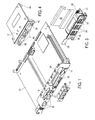
- Figures 1 and 2 show a first embodiment a base circuit board 10 of an otherwise not shown electronic device together with an additional circuit board 12 (Fig. 1) in different perspective Views.
- a connector panel 14 At one edge of the base circuit board 10 attached a connector panel 14 through which different attached to the base circuit board 10 and for the Connection of other devices protrude through certain connectors 16.
- the connector panel diaphragm 14 Sockets 17 built according to the USB standard, the electrical are connected to the base circuit board 10.
- the connector panel 14 carries a first recess 18 for the installation of a printer connector and another Recess 20 for the connection panel of a not shown AT expansion boards. Is essential to the invention especially the one introduced into the connector panel 14 Breakthrough 22.
- the base circuit board is with a first Connector 26 and close to the connector panel 14th parallel edge of the opening 22 with another Connector 28 populated.
- the base circuit board can be seen 10 in an area adjacent to the opening 22 provide a cutout 24 of at least one such size, that the additional circuit board 12 can be accommodated therein.
Landscapes
- Engineering & Computer Science (AREA)
- Theoretical Computer Science (AREA)
- Power Engineering (AREA)
- Human Computer Interaction (AREA)
- Physics & Mathematics (AREA)
- General Engineering & Computer Science (AREA)
- General Physics & Mathematics (AREA)
- Details Of Connecting Devices For Male And Female Coupling (AREA)
- Combinations Of Printed Boards (AREA)
Abstract
Description
- Fig. 1
- ein erstes Ausführungsbeispiel einer Basisleiterplatte zusammen mit einer Zusatzleiterplatte in perspektivischer Draufsicht,
- Fig. 2
- die Basisleiterplatte aus Fig. 1 in einer anderen Perspektive,
- Fig. 3
- ein erstes Ausführungsbeispiel einer Zusatzleiterplatte in perspektivischer Draufsicht,
- Fig. 4
- ein zweites Ausführungsbeispiel einer Zusatzleiterplatte in perspektivischer Draufsicht,
- Fig. 5
- ein zweites Ausführungsbeispiel einer Basisleiterplatte zusammen mit einer Zusatzleiterplatte in perspektivischer Draufsicht.
Claims (11)
- PC-basiertes elektronisches Gerät mit einer Basisleiterplatte (10, 10') und wenigstens einer Peripheriegeräte-Schnittstelle, dadurch gekennzeichnet ,daß wahlweise wenigstens einer von mehreren, jeweils einem anderen Schnittstellen-Standard genügenden Peripheriegeräte-Anschlußsteckern (34, 34', 46) in das Gerät einsetzbar ist.
- Elektronisches Gerät nach Anspruch 1, deren Peripheriegeräte-Anschlußstecker (46) dem IEEE RS 232-Standard genügt.
- Elektronisches Gerät nach Anspruch 1, deren Peripheriegeräte-Anschlußstecker (34, 34') dem USB-Standard genügt.
- Elektronisches Gerät nach einem der Ansprüche 1 bis 3 mit einer Zusatzleiterplatte (12; 12', 12", 12'''), auf der wenigstens ein Peripheriegeräte-Anschlußstecker (34, 34', 46) oder eine Mehrzahl von dem selben Schnittstellen-Standard genügenden Peripheriegeräte-Anschlußsteckern (34, 34', 46) oder auch zusätzlich wenigstens ein Schnittstellentreiber oder Teile davon angeordnet ist.
- Elektronisches Gerät nach Anspruch 4, bei der die Zusatzleiterplatte (12; 12', 12", 12''') mit der Basisleiterplatte (10, 10') mechanisch und elektrisch verbindbar oder verbunden ist, wobzu an einem Rand der Basisleiterplatte (10, 10') eine Anschlußfeld-Blende (14, 14') mit wenigstens einem Durchbruch (22, 22') zumindest für den wenigstens einen Peripheriegeräte-Anschlußstecker 34, 34', 46) angeordnet ist.
- Elektronisches Gerät nach Anspruch 5, bei der die Zusatzleiterplatte (12; 12', 12") an einer Kante mit einer den wenigstens einen Peripheriegeräte-Anschlußstecker (34, 46) tragenden Anschlußblende (30, 42) versehen ist und
der Durchbruch (22) derart bemessen ist, daß die Zusatzleiterplatte (12; 12', 12") mit ihrer der einen Kante gegenüberliegenden Kante voran von außen in den Durchbruch (22) einschiebbar ist, bis die Anschlußblende (30, 42) der Zusatzleiterplatte (12; 12', 12") außen an der Anschlußfeld-Blende (14) anliegt und die Anschlußblende (34, 46) die Ränder des Durchbruchs (22) wenigstens teilweise überdeckt. - Elektronisches Gerät nach Anspruch 5, bei der die Zusatzleiterplatte (12''') an einer Kante mit wenigstens einem Peripheriegeräte-Anschlußstecker (34') versehen ist,
der Durchbruch (22') derart bemessen ist, daß bei auf der Geräte-Innenseite an der Anschlußfeld-Blende (14') anliegender Zusatzleiterplatte (12''') der wenigstens eine Peripheriegeräte-Anschlußstecker (34') mit einem komplementären Stecker durch den Durchbruch (22') von außen her erreichbar ist, und
ein den wenigstens einen Peripheriegeräte-Anschlußstecker (34') freilassendes Abdeckblech (48) vorgesehen ist, das von außen derart an der Anschlußfeld-Blende (14') befestigt ist, daß es die Ränder des Durchbruchs (22') wenigstens teilweise überdeckt. - Elektronisches Gerät nach einem der Ansprüche 5 bis 7, bei dem das Abdeckblech (48) oder die Anschlußblende (30) der Zusatzleiterplatte (12', 12''') mit einer Fahne (38, 38') versehen ist, dazu bestimmt ist, die zumindest eine in die Anschlußfeld-Blende (14, 14') sonst noch eingebaute Steckbuchse (17) zu überdecken.
- Elektronisches Gerät nach einem der Ansprüche 5 bis 8, deren Basisleiterplatte (10, 10') in einem an den Durchbruch (22, 22') grenzenden Bereich mit einem Ausschnitt (24) wenigstens von der Größe der Zusatzleiterplatte (12', 12''') versehen ist.
- Elektronisches Gerät nach einem der Ansprüche 5 bis 9, bei dem die Basisleiterplatte (10) einen ersten Steckverbinder (26) und die Zusatzleiterplatte (12') einen zweiten Steckverbinder (32) trägt und der erste Steckverbinder (26) mit dem zweiten Steckverbinder (32) über eine vieladrige elektrische Verbindung, insbesondere ein Flachbandkabel (40) verbunden ist oder wird.
- Elektronisches Gerät nach einem der Ansprüche 5 bis 9, bei dem die Basisleiterplatte (10) einen dritten Steckverbinder (28) und die Zusatzleiterplatte (12") einen dazu komplementären Gegensteckverbinder (44) trägt, auf den die Zusatzleiterplatte (12") direkt aufsteckbar ist.
Applications Claiming Priority (2)
| Application Number | Priority Date | Filing Date | Title |
|---|---|---|---|
| DE20113394U | 2001-08-11 | ||
| DE20113394U DE20113394U1 (de) | 2001-08-11 | 2001-08-11 | Elektronisches Gerät mit auswechselbarem Peripheriegeräte-Anschlußstecker |
Publications (2)
| Publication Number | Publication Date |
|---|---|
| EP1289357A2 true EP1289357A2 (de) | 2003-03-05 |
| EP1289357A3 EP1289357A3 (de) | 2005-06-01 |
Family
ID=7960476
Family Applications (1)
| Application Number | Title | Priority Date | Filing Date |
|---|---|---|---|
| EP02015392A Withdrawn EP1289357A3 (de) | 2001-08-11 | 2002-07-11 | Elektronisches Gerät mit auswechselbarem Peripheriegeräte-Anschlussstecker |
Country Status (2)
| Country | Link |
|---|---|
| EP (1) | EP1289357A3 (de) |
| DE (1) | DE20113394U1 (de) |
Family Cites Families (3)
| Publication number | Priority date | Publication date | Assignee | Title |
|---|---|---|---|---|
| US5650911A (en) * | 1995-10-24 | 1997-07-22 | Dell U.S.A., L.P. | Apparatus for the expansion of computer chassis input/output connections |
| US6078504A (en) * | 1997-10-08 | 2000-06-20 | Cisco Systems, Inc. | Universal adapter bracket for communications devices |
| DE19827709A1 (de) * | 1998-06-22 | 1999-12-30 | Siemens Nixdorf Inf Syst | Anordnung einer Steckbaugruppe im Gehäuse eines Datenverarbeitungsgerätes |
-
2001
- 2001-08-11 DE DE20113394U patent/DE20113394U1/de not_active Expired - Lifetime
-
2002
- 2002-07-11 EP EP02015392A patent/EP1289357A3/de not_active Withdrawn
Also Published As
| Publication number | Publication date |
|---|---|
| EP1289357A3 (de) | 2005-06-01 |
| DE20113394U1 (de) | 2001-10-18 |
Similar Documents
| Publication | Publication Date | Title |
|---|---|---|
| DE69206938T2 (de) | Modulare auswechselbare Energieverteilungsvorrichtung | |
| DE69211833T2 (de) | Installationseinrichtung für Netzanschluss | |
| DE4217205C2 (de) | Steckverbinder | |
| DE4314908C2 (de) | Buchse für einen Steckverbinder | |
| DE69630334T2 (de) | Steckverbinder für gedruckte Schaltung | |
| DE19706536C2 (de) | Montageanordnung für ein elektrisches Modul | |
| DE2800006A1 (de) | Universell programmierbarer kurzschliesstecker fuer eine steckfassung einer integrierten schaltung | |
| EP0853022B1 (de) | Funktionsmodul für Kraftfahrzeuge | |
| DE69931591T2 (de) | Leiterplatte für Modularstecker | |
| DE2717372C3 (de) | Baugruppe aus einem Digitalschalter und elektronischen Bauelementen | |
| DE69006167T2 (de) | Verbesserte flächige Trägerstruktur für Leiterplatte. | |
| DE3876765T2 (de) | Anordnung zum festhalten einer gedruckten schaltung auf einem gestell | |
| DE69512344T2 (de) | Drahteinführungsabdeckung für Schneidklemmverbinder | |
| EP1039589A1 (de) | Verteiler zum Verbinden von Aktoren und/oder Sensoren | |
| DE69432498T2 (de) | Elektrischer Ein-Ausgangsverbinder | |
| EP0784354A2 (de) | Hochstrom-Kabelklemme für eine Leiterplattenanordnung | |
| DE102024137044A1 (de) | Riser-karte für den vertikalen einbau einer erweiterungskarte | |
| DE4106453C1 (de) | ||
| EP0156981B1 (de) | Zusatzgerät für einen Elektrizitätszähler | |
| DE2340773A1 (de) | Uebergabesteckverbindung | |
| EP0863691B1 (de) | Elektrisches Gerät | |
| WO2022189046A1 (de) | Steckervorrichtung zum befestigen von elektronischen komponenten auf einer leiterplatte | |
| DE20113394U1 (de) | Elektronisches Gerät mit auswechselbarem Peripheriegeräte-Anschlußstecker | |
| EP0688157A2 (de) | Gehäuse für elektronische Steckbaugruppen | |
| DE69725269T2 (de) | Elektrischer Verbinder mit Stift-Halterung |
Legal Events
| Date | Code | Title | Description |
|---|---|---|---|
| PUAI | Public reference made under article 153(3) epc to a published international application that has entered the european phase |
Free format text: ORIGINAL CODE: 0009012 |
|
| AK | Designated contracting states |
Kind code of ref document: A2 Designated state(s): AT BE BG CH CY CZ DE DK EE ES FI FR GB GR IE IT LI LU MC NL PT SE SK TR Designated state(s): AT BE BG CH CY CZ DE DK EE ES FI FR GB GR IE IT LI LU MC NL PT SE SK TR |
|
| AX | Request for extension of the european patent |
Extension state: AL LT LV MK RO SI |
|
| PUAL | Search report despatched |
Free format text: ORIGINAL CODE: 0009013 |
|
| AK | Designated contracting states |
Kind code of ref document: A3 Designated state(s): AT BE BG CH CY CZ DE DK EE ES FI FR GB GR IE IT LI LU MC NL PT SE SK TR |
|
| AX | Request for extension of the european patent |
Extension state: AL LT LV MK RO SI |
|
| RIC1 | Information provided on ipc code assigned before grant |
Ipc: 7G 06F 1/18 A |
|
| 17P | Request for examination filed |
Effective date: 20050705 |
|
| AKX | Designation fees paid |
Designated state(s): DE FR GB |
|
| 17Q | First examination report despatched |
Effective date: 20060928 |
|
| STAA | Information on the status of an ep patent application or granted ep patent |
Free format text: STATUS: THE APPLICATION HAS BEEN WITHDRAWN |
|
| 18W | Application withdrawn |
Effective date: 20070124 |