EP1289168A1 - Verfahren zur Funkübertragung von digitalen Nachrichtensignalen - Google Patents
Verfahren zur Funkübertragung von digitalen Nachrichtensignalen Download PDFInfo
- Publication number
- EP1289168A1 EP1289168A1 EP02018880A EP02018880A EP1289168A1 EP 1289168 A1 EP1289168 A1 EP 1289168A1 EP 02018880 A EP02018880 A EP 02018880A EP 02018880 A EP02018880 A EP 02018880A EP 1289168 A1 EP1289168 A1 EP 1289168A1
- Authority
- EP
- European Patent Office
- Prior art keywords
- antenna
- receiver
- lobes
- transmission
- transmitter
- Prior art date
- Legal status (The legal status is an assumption and is not a legal conclusion. Google has not performed a legal analysis and makes no representation as to the accuracy of the status listed.)
- Granted
Links
Images


Classifications
-
- H—ELECTRICITY
- H04—ELECTRIC COMMUNICATION TECHNIQUE
- H04L—TRANSMISSION OF DIGITAL INFORMATION, e.g. TELEGRAPHIC COMMUNICATION
- H04L1/00—Arrangements for detecting or preventing errors in the information received
- H04L1/02—Arrangements for detecting or preventing errors in the information received by diversity reception
- H04L1/06—Arrangements for detecting or preventing errors in the information received by diversity reception using space diversity
- H04L1/0618—Space-time coding
-
- H—ELECTRICITY
- H04—ELECTRIC COMMUNICATION TECHNIQUE
- H04B—TRANSMISSION
- H04B7/00—Radio transmission systems, i.e. using radiation field
- H04B7/02—Diversity systems; Multi-antenna system, i.e. transmission or reception using multiple antennas
- H04B7/04—Diversity systems; Multi-antenna system, i.e. transmission or reception using multiple antennas using two or more spaced independent antennas
- H04B7/06—Diversity systems; Multi-antenna system, i.e. transmission or reception using multiple antennas using two or more spaced independent antennas at the transmitting station
- H04B7/0613—Diversity systems; Multi-antenna system, i.e. transmission or reception using multiple antennas using two or more spaced independent antennas at the transmitting station using simultaneous transmission
- H04B7/0615—Diversity systems; Multi-antenna system, i.e. transmission or reception using multiple antennas using two or more spaced independent antennas at the transmitting station using simultaneous transmission of weighted versions of same signal
- H04B7/0617—Diversity systems; Multi-antenna system, i.e. transmission or reception using multiple antennas using two or more spaced independent antennas at the transmitting station using simultaneous transmission of weighted versions of same signal for beam forming
-
- H—ELECTRICITY
- H04—ELECTRIC COMMUNICATION TECHNIQUE
- H04B—TRANSMISSION
- H04B7/00—Radio transmission systems, i.e. using radiation field
- H04B7/02—Diversity systems; Multi-antenna system, i.e. transmission or reception using multiple antennas
- H04B7/04—Diversity systems; Multi-antenna system, i.e. transmission or reception using multiple antennas using two or more spaced independent antennas
- H04B7/06—Diversity systems; Multi-antenna system, i.e. transmission or reception using multiple antennas using two or more spaced independent antennas at the transmitting station
- H04B7/0613—Diversity systems; Multi-antenna system, i.e. transmission or reception using multiple antennas using two or more spaced independent antennas at the transmitting station using simultaneous transmission
- H04B7/0667—Diversity systems; Multi-antenna system, i.e. transmission or reception using multiple antennas using two or more spaced independent antennas at the transmitting station using simultaneous transmission of delayed versions of same signal
- H04B7/0669—Diversity systems; Multi-antenna system, i.e. transmission or reception using multiple antennas using two or more spaced independent antennas at the transmitting station using simultaneous transmission of delayed versions of same signal using different channel coding between antennas
-
- H—ELECTRICITY
- H04—ELECTRIC COMMUNICATION TECHNIQUE
- H04B—TRANSMISSION
- H04B7/00—Radio transmission systems, i.e. using radiation field
- H04B7/02—Diversity systems; Multi-antenna system, i.e. transmission or reception using multiple antennas
- H04B7/04—Diversity systems; Multi-antenna system, i.e. transmission or reception using multiple antennas using two or more spaced independent antennas
- H04B7/08—Diversity systems; Multi-antenna system, i.e. transmission or reception using multiple antennas using two or more spaced independent antennas at the receiving station
- H04B7/0837—Diversity systems; Multi-antenna system, i.e. transmission or reception using multiple antennas using two or more spaced independent antennas at the receiving station using pre-detection combining
- H04B7/0842—Weighted combining
- H04B7/086—Weighted combining using weights depending on external parameters, e.g. direction of arrival [DOA], predetermined weights or beamforming
-
- H—ELECTRICITY
- H04—ELECTRIC COMMUNICATION TECHNIQUE
- H04B—TRANSMISSION
- H04B7/00—Radio transmission systems, i.e. using radiation field
- H04B7/02—Diversity systems; Multi-antenna system, i.e. transmission or reception using multiple antennas
- H04B7/04—Diversity systems; Multi-antenna system, i.e. transmission or reception using multiple antennas using two or more spaced independent antennas
- H04B7/08—Diversity systems; Multi-antenna system, i.e. transmission or reception using multiple antennas using two or more spaced independent antennas at the receiving station
- H04B7/0891—Space-time diversity
Definitions
- the invention relates to a method for radio transmission of digital message signals from a transmitter to a receiver using diversity and coding measures.
- the multipath of a signal in the transmission channel of radio systems causes constructive and destructive Superimposition of the signal on the receiving antenna.
- Critical is the resulting signal loss that leads to this can cause the quality of the radio link very much becomes bad and the connection is no longer maintained can be.
- the power control increases the interference in a radio system, because it disturbs other participants more can. This approach also goes against the goal of throughput to optimize data, since increased transmission power in unfavorable transmission channels, which is then wasted no longer available for the good transmission channels stands.
- space-time coding With space-time coding, at least two are isotropic Transmitting antennas or one or more receiving antennas used.
- the sole use of space-time coding offers therefore no possibility for targeted spatial distribution the transmission power or transmission signal currents.
- the object of the invention is in a radio transmission system for digital message signals through the transmission power Targeted use of the topographical conditions of the channel to be addressed to the recipient, the negative impact of signal fading in the multipath propagation channel is reduced and the required transmission power and therefore also the interference in the radio system can be minimized.
- this problem is solved in that several transmitting antenna lobes of one or more intelligent Antenna groups of the transmitter under control by means of an adaptive Antenna processor using the topographic Channel conditions are aimed specifically at the receiver and that on the individual antenna lobes what is to be transmitted Message signal in different directions in such a way differently modified form is broadcast, that in the receiver the spectrum of that is there via a receiving antenna received signal specifically formed and from the thus obtained Signal the message signal can be detected.
- the method according to the invention thus enables the Transmission power by using the topographical conditions of the transmission channel to the recipient judge.
- This procedure helps with a suitable modification of the transmission signal such that the spectrum of the reception signal can be influenced so that the recipient in is able to correctly detect this signal.
- This The process therefore reduces the negative effects of the signal loss in the multipath propagation channel quite essential and it minimizes the required transmission power and therefore also the interference in the respective radio system.
- the transmission channels between the individual clubs and the Receiving stations are usually uncorrelated.
- the broadcast signals on the individual clubs can be different Criteria are modified.
- the starting scenario is sending of the same signal over several transmitting antenna lobes, where the antenna beams are aligned so that the signals reach the recipient in different ways. This Scenario enables the available transmission power aimed specifically at the recipient, with the Use of several transmitting antenna lobes with different ones Transmission channels significantly improved the reception quality can be.
- the transmission channel of a club is subject to a strong one Signal loss with which a connection is no longer possible, see above there is a high probability that the channel is one or several other clubs sufficient transmission quality provides and maintain the connection can be.
- the modification is specific to the invention of the transmission signal at the individual transmission antenna lobes.
- Fig.1a The combination shown in Fig.1a with isotropic antenna on transmitter 1 and intelligent, multi-lobe antenna on the receiver 2 makes it possible to overlap the individual propagation paths to prevent. This is both compensation the transit time difference (here between the radio transmission path 1 ⁇ and 2 ⁇ ) as well as the suppression of radio transmission paths (here radio transmission path 3 ⁇ ) possible.
- Fig.1b with intelligent, multi-lobe antenna on transmitter 1 and isotropic antenna on Receiver 2 offers the possibility of targeting the transmission power and with known channel parameters, optimal in terms of information theory to distribute. Here too there is - if the channel is known - the possibility to compensate for the runtime differences. These maturity differences are mainly for frequency selective fading responsible.
- Fig.1c with intelligent, multi-lobe antenna on transmitter 1 and also more intelligent, multi-lobe antenna on receiver 2 combines the properties the combinations of Fig.1a and 1b.
- Fig.1c is recognizable, due to the spatial selectivity Sender 1 and receiver 2 several - ideally independent - Transmission channels on which the transmission power and the transmitted Information based on information theory can be distributed.
- space-time coding can be combined can be used very flexibly with intelligent antennas, because of the targeted spatial alignment of the antenna characteristics a spatial distribution of the transmission power at the transmitter and the signal currents is made possible.
- the one in the process setting of the receiving antenna characteristic provided according to the invention also allows targeted Selection of spatially separate paths of propagation, what, in Combination with an intelligent transmission antenna, a signal separation allows.
- a connection between space-time coding and intelligent antennas at transmitter 1 and receiver 2 is shown schematically in FIG.
- a space-time encoder 3 supplies from a data stream ⁇ a number of N differently modified signal streams M, which are processed by an adaptive antenna processor 4.
- the antenna processor 4 controls a connected antenna group 5 in such a way that the N modified signal currents M are emitted in different spatial directions 6, 7, 8 in accordance with the propagation scenario.
- an adaptive antenna processor 10 connected to an antenna group 9 delivers the N different signal currents M by specifically adjusting the antenna characteristics of the antenna group 9 in accordance with the reception directions.
- the N signal streams M are then decoded in a space-time decoder 11, so that the data stream ⁇ can be extracted.
- the number of lobes on the receiving and transmitting sides need not necessarily be the same.
- the following advantages thus result the state of the art.
- aligning several Transmission lobes on a receiver via different propagation paths there are new methods for using diversity in the receiver. These methods make it possible Target spectrum of the received signal so that it can be detected in the receiver with less loss in comparison to conventional processes.
- the distribution of the channel errors can be influenced that these can be corrected in the receiver.
- Classical Procedures with intelligent antennas are unable the spectrum and thus the error distribution in the receiver to influence that e.g. in the critical shrink channel without Frequency selectivity a connection without any of the other, measures previously described are maintained can.
- the method according to the invention comes with channel coding, due to a more favorable channel error distribution, with less Redundancy than the conventional radio systems.
- they are also received intelligent antennas used, then the signal / interference ratio through maximum ratio combining be optimized.
- Performance optimization is inherent in the method according to the invention, with only performance towards the recipient is emitted, causing interference in the overall system is reduced.
- Other design options and advantages the method according to the invention, e.g. the one Soft handovers are listed below.
- the signals can be sent to the individual clubs delayed in time to each other or in the Phase shifted to each other. This can be as a time spread of the transmission signal can be viewed. Since the time spread of the signal to be transmitted is a Causes frequency selectivity in the spectrum of the received signal, can use this method to artificially frequency selectivity of the spectrum of the received signal become.
- the goal is e.g. in the case of a fading channel without frequency selectivity, to create them artificially to avoid cases in which the entire signal spectrum is in one there is deep shrinkage and there is significant disruption and Impairment of reception in the receiver comes up to Total system failure.
- the reception signal can be a long time subject to strong signal loss and break the connection. But if an artificial time variance is brought about, the temporal signal fading is relatively short and the transmission errors that occur can be suitably e.g. by channel coding.
- the efficiency of the two measures described so far can by scrambling the data in the transmitter with an interleaver be improved. With an OFDM transmission this can be a time and / or frequency interleaving. The recipient provides the corresponding deinterleaver.
- the total number of subcarriers can be divided into N groups, where N should suitably correspond to the number of transmission lobes.
- N should suitably correspond to the number of transmission lobes.
- Each group of subcarriers should be broadcast on a different broadcasting lobe.
- the subcarriers should be selected in such a way that the subcarriers of the individual groups are interleaved in order to use the frequency diversity of the transmission channel appropriately.
- the probability is high that the Subcarriers broadcast over another club, can be received with sufficient transmission quality, since the channels are usually uncorrelated to one another. Is this new combination e.g. with a channel coding connected, this can appropriately identify the errors the subcarriers with the bad channel with the help of the subcarriers correct with good channel properties.
- space-time coding can be Receiving antennas with several lobes that are paired on top of each other are adapted to further increase. This allows separate Propagation channels can be realized which the previously Prevent mentioned signal overlap on the receiver and both a targeted distribution of the information on the transmitter and also processing of the received signals (and not only allow their superposition) on the individual clubs. In the Use of space-time coding must be a suitable one at the receiving end Decoders are available.
- the receiving side can have different ones Concepts to improve the performance of the system be implemented.
- the data rate can also be improved by a further development of the invention of the system can be increased by groups of transmit and Reception lobes are assigned to each other and one each form a pair on the transmitting side and a receiving side group, that provides a data channel. This means, that multiple data channels simultaneously in the same frequency band can be built between two radios. This Continuing education enables the data rate of the system to be targeted adapt to the requirements of the application. So can Data channels can be flexibly switched on or off. This flexibility is not the case with today's transmission methods.
- the individual features and developments of the invention can be combined with each other and thus enable further improvement of the transmission properties of the system.
- the invention improves the possibilities of the transmission power more targeted to the recipient and thereby to minimize the required transmission power.
- MC-CDM multi-carrier code division multiplexing
- a recipient of a mobile Radio not only receives its data from a base station received, but several clubs from different base stations can send the receiver of the radio data according to one or more features of the invention are modified, send.
- the mobile radio has several clubs to send available, this can be done in the opposite direction its data not only to one but to several base stations according to one or more features of the invention send modified. Simplify these two options also the process of a soft handover, in which the mobile Radio changes the cooperating base station, being already a connection via one or more clubs to the new one Base station exists before connecting via one or several other clubs are dismantled to the old base station.
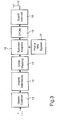
- FIG. 3 is a block diagram for a standard DVB-T transmitter shown from the inner coding. As can be seen in Fig. 3 is in this example a transmitter antenna on the transmitter side 12 used with isotropic antenna characteristics.
- Inner encoder 13, inner interleaver 14, QAM mapper 15, frame adapter 16, pilot & TPS signal processing 17, OFDM modulator 18 and protection (guard) interval inserter 19 becomes European Telecommunications Standard Institute ETSI: "Digital Video Broadcasting (DVB); framing structure, channel coding and modulation for digital terrestrial television ", July 1999, EN 300 744 V 1.2.1.
- ETSI European Telecommunications Standard Institute
- DVB Digital Video Broadcasting
- DVB-T Digital Video Broadcasting Terrestrial
- the DVB-T standard is based on to the already standardized systems for cable and satellite transmission has been developed.
- the inner encoder 13 to which the externally coded, digital data signal ⁇ is supplied, the inner interleaver 14, the frequency selective occurring in the radio field Disturbances spread over many data symbols. Error correction in the receiver can therefore be more effective work.
- the OFDM frame by summarizing and positioning data symbols and pilot symbols from the Pilot & TPS signal conditioning 17 generated.
- An OFDM frame again consists of individual OFDM symbols.
- OFDM Orthogonal Frequency Division Multiplex
- Multi-carrier modulation method in which the one to be transmitted Total data stream on one corresponding to the number of subcarriers Number of data streams is split.
- guard interval inserter 19 can be highly insensitive to Intersymbol interference is typically achieved occur with multipath propagation of terrestrial radio signals.
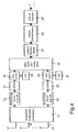
- An intelligent antenna unit consisting of an antenna array 20 and an adaptive antenna processor 21, is followed by N identical, parallel processing branches, each with a guard interval remover 22, an IOFDM 23, an equalizer 24 and a CSI (channel State information; channel 25).
- N is the number of propagation paths (or antenna lobes) that are processed at the receiver.
- the digital signal streams M from the N paths are combined in a device 26 with maximum ratio combining and QAM demodulated and then, according to FIG. 4, descrambled in a symbol deinterleaver 27 and an inner deinterleaver 28 and decoded in an inner decoder 29, so that the data stream ⁇ results.
- a device 26 with maximum ratio combining and QAM demodulated and then, according to FIG. 4, descrambled in a symbol deinterleaver 27 and an inner deinterleaver 28 and decoded in an inner decoder 29, so that the data stream ⁇ results.
- perfect knowledge of the channel state CSI and perfect adaptation of the antenna lobes to the reception directions was assumed.
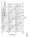
- FIG. 5 shows the bit error rates of the systems under consideration as a function of the signal / noise power ratio E S / N 0 .
- a system with an isotropic receiving antenna was simulated (triangular markers).
- the system is targeted with three Receiving antennas a perfect alignment of the antenna lobes accepted.
- This directional characteristic is in the simulation is only used to determine the directions of propagation separate paths or paths (spatially). This means that the antenna gain resulting from the group characteristics of the intelligent Antenna results, not considered here is.
- the bit error curve shifts by this gain (square markers) of the 3-antenna system with directional Antennas to the left.
- GSNR 4.77 dB (see Fig. 5, square markers, solid line).
- the present invention is of great interest to the Information and communication technology and can among other things the transmission quality and capacity of existing radio systems as well as future radio systems.
- the method according to the invention is implemented in this way can be that it is also in systems according to existing ones Standards can be used without any modification of the respective standard is required.
Landscapes
- Engineering & Computer Science (AREA)
- Computer Networks & Wireless Communication (AREA)
- Signal Processing (AREA)
- Radio Transmission System (AREA)
- Mobile Radio Communication Systems (AREA)
Abstract
Description
- eine Kanalcodierung, mit der auf Kosten von Redundanz im Datenstrom Übertragungsfehler in begrenztem Maße korrigiert werden können.
- eine Leistungsregelung, die bei starken Signaldämpfungen die Sendeleistung anhebt, um die Verbindung aufrecht zu erhalten;
- Diversity-Techniken, bei denen mehrere Sende- und/oder Empfangsantennen eingesetzt werden, wodurch mehrere unabhängig voneinander gestörte Signale am/im Empfänger überlagert werden und die Datendetektion zuverlässiger wird (siehe beispielsweise S. Kaiser: "Spatial transmit diversity techniques for broadband OFDM systems," in Proc. IEEE Global Telecommun. Conf. (GLOBECOM 2000), San Francisco, USA, S. 1824-1828, Nov./Dez. 2000.);
- Space-Time-Coding (siehe beispielsweise V. Tarokh und N. Seshadri und A. R. Calderbank: "Space-Time Codes for High Data Rate Wireless Communication: Performance Criterion and Code Construction", IEEE Transactions on Information Theory, Vol. 44, No. 2, S. 744-764, März 1998), das zusätzlich Redundanz in "Raumrichtung" einfügt. Dabei werden über mehrere Sendeantennen gleichzeitig verschiedene codierte Signale abgestrahlt, die über eine oder mehrere Empfangsantennen empfangen werden;
- Intelligente Antennen (L.C. Godara: "Applications of Antenna Arrays to Mobile Communications, Part I: Performance Improvement, Feasibility, and System Considerations," Proceedings of the IEEE, Vol. 85, No. 7, S. 1031-1060; L.C. Godara: "Applications of Antenna Arrays to Mobile Communications, Part II: Beam-Forming and Direction-of-Arrival Considerations," Proceedings of the IEEE, Vol. 85, No. 8, S. 1195-1245) kombinieren auf "intelligente" Art mittels eines adaptiven Antennenprozessors mehrere Signale in Empfangs- oder Senderichtung mit verschiedenen Antennenelementen. Die Sendesignale werden mittels Antennenkeulen in Richtung der besten Signalwege für den Empfänger ausgesendet. Die zur Verfügung stehende Sendeleistung wird optimal gebündelt, und Interferenz im zellularen Funksystem minimiert. Die Empfangssignale werden durch das Ausrichten der Keulen einer intelligenten Antenne am Empfänger optimal empfangen und Störsignale unterdrückt.
- Fig.1a bis 1c
- beispielhaft Szenarien für die Anwendung von intelligenten Antennen am Sender und/oder Empfänger,
- Fig.2
- in einem Blockschaltbild die Verknüpfung zwischen Space-Time-Coding und intelligenten Antennen auf der Sende- und Empfangsseite,
- Fig.3
- das Blockschaltbild eines Beispiels einer DVB-T-Senderimplementierung,
- Fig.4
- das Blockschaltbild eines Beispiels einer DVB-T-Empfängerimplementierung mit gerichteten Antennenkeulen, und
- Fig.5
- die ermittelten Bitfehlerraten über das Signal/Rauschleistungsverhältnis (ES/N0) bei dem anhand von Fig.3 und Fig.4 betrachteten DVB-T-Funksystembeispiel.
| Pfad-# | Pfad-Verzögerung [µs] | mittlere rel. Leistung [dB] | Fading-Charakteristik | max. Doppler [Hz] | Doppler-Spektrum-Form |
| 1 | 0 | 0 | Rayleigh | 50 | Jakes |
| 2 | 5 | 0 | Rayleigh | 50 | Jakes |
| 3 | 15 | 0 | Rayleigh | 50 | Jakes |

- 1
- Sender
- 2
- Empfänger
- 3
- Space-Time-Encoder
- 4
- Adaptiver Antennenprozessor
- 5
- Antennengruppe
- 6, 7, 8
- Raumrichtungen
- 9
- Antennengruppe
- 10
- Adaptiver Antennenprozessor
- 11
- Space-Time-Decodierer
- 12
- Sendeantenne
- 13
- Innerer Codierer
- 14
- Innerer Interleaver
- 15
- QAM-Mapper
- 16
- Rahmen(Frame)-Adapter
- 17
- Pilot&TPS-Signalaufbereitung
- 18
- OFDM-Modulator
- 19
- Schutz(Guard)-Intervall-Einfüger
- 20
- Antennenarray
- 21
- Adaptiver Antennenprozessor
- 22
- Schutz(Guard)-Intervall-Entferner
- 23
- IOFDM
- 24
- Entzerrer
- 25
- CSI(Channel State Information; Kanalzustand)-Geber
- 26
- Einrichtung mit Maximum Ratio Combining
- 27
- Symbol-Deinterleaver
- 28
- Innerer Deinterleaver
- 29
- Innerer Decodierer
- 1○, 2○, 3○
- Funkübertragungspfade
Claims (19)
- Verfahren zur Funkübertragung von digitalen Nachrichtensignalen von einem Sender zu einem Empfänger unter Verwendung von Diversity- und Codierungsmaßnahmen, dadurch gekennzeichnet, dass mehrere Sendeantennenkeulen einer oder mehrerer intelligenter Antennengruppen (5) des Senders (1) unter Steuerung mittels eines adaptiven Antennenprozessors (4) bei Ausnutzung der topographischen Kanalgegebenheiten gezielt auf den Empfänger (2) gerichtet werden und dass auf den einzelnen Antennenkeulen das zu übertragende Nachrichtensignal in verschiedenen Richtungen in jeweils derart unterschiedlich modifizierter Form ausgestrahlt wird, dass im Empfänger das Spektrum des dort über eine Empfangsantenne empfangenen Signals gezielt geformt und aus dem so gewonnenen Signal das Nachrichtensignal detektiert werden kann.
- Verfahren nach Anspruch 1, dadurch gekennzeichnet, dass die vom Sender (1) über die verschiedenen Sendeantennenkeulen übertragenen modifizierten Signale im Empfänger (2) mit mehreren Empfangsantennenkeulen einer intelligenten Antennengruppe (9) unter Steuerung mittels eines adaptiven Antennenprozessors (10) aufgenommen werden und dass anschließend die empfangenen Signalströme decodiert werden.
- Verfahren nach Anspruch 2, dadurch gekennzeichnet, dass das Signal/Störleistungs-Verhältnis im Empfänger durch Maximum-Ratio-Combining optimiert wird.
- Verfahren nach einem der vorhergehenden Ansprüche, dadurch gekennzeichnet, dass im Sender eine redundanzbildende Kanalcodierung des zu übertragenden Nachrichtensignals vorgenommen wird, die im Empfänger bei der Decodierung wieder rückgängig gemacht wird.
- Verfahren nach einem der Ansprüche 1 bis 3, gekennzeichnet durch den Einsatz von Multi-Carrier-Code-Division-Multiplexing (MC-CDM), das keine Ratenverluste aufweist und die Übertragungsqualität durch geeignete Ausnutzung von Zeitund/oder Frequenzdiversity verbessert.
- Verfahren nach Anspruch 1, dadurch gekennzeichnet, dass die auf den einzelnen Sendeantennenkeulen vom Sender ausgehenden Signale zur Modifizierung zeitlich zueinander verzögert ausgesendet werden.
- Verfahren nach Anspruch 1, dadurch gekennzeichnet, dass die auf den einzelnen Antennenkeulen vom Sender ausgehenden Signale zur Modifizierung in der Phase zueinander verschoben ausgesendet werden.
- Verfahren nach Anspruch 7, dadurch gekennzeichnet, dass die Phasenverschiebung der auf den einzelnen Antennenkeulen ausgesendeten Signale zeitlich zueinander veränderlich ist.
- Verfahren nach einem der Ansprüche 6 bis 8, dadurch gekennzeichnet, dass die digitalen Nachrichtensignale im Sender mit einem Interleaver verwürfelt und im Empfänger entsprechend in einem Deinterleaver entwürfelt werden.
- Verfahren nach einem der vorhergehenden Ansprüche, dadurch gekennzeichnet, dass bei einer OFDM-Übertragung mit einem Zeit- und/oder Frequenzinterleaving verwürfelt wird.
- Verfahren nach einem der vorhergehenden Ansprüche, dadurch gekennzeichnet, dass bei Systemen mit Mehrträgermodulation, wie z.B. OFDM, die Gesamtzahl der Unterträger in N Gruppen aufgeteilt wird, wobei N in geeigneter Weise der Anzahl der Sendeantennenkeulen entsprechen sollte, dass jede Gruppe der Unterträger über eine andere Sendeantennenkeule ausgestrahlt wird und dass bei der Zuordnung der Unterträger zu den einzelnen Gruppen die Unterträger so gewählt werden, dass die Unterträger der einzelnen Gruppen verwürfelt sind.
- Verfahren nach einem der vorhergehenden Ansprüche, gekennzeichnet durch ein schnelles Wechseln der Sendeantennenkeulen derart, dass digitale Nachrichtensignale nur auf denjenigen Sendeantennenkeulen ausgesendet werden, auf denen der Übertragungskanal keinem signifikanten Schwund unterworfen ist.
- Verfahren nach einem der vorhergehenden Ansprüche, gekennzeichnet durch eine geeignete Kombination der einzelnen Sendeantennenkeulen mit Space-Time-Codierung, bei welcher Redundanz nicht nur in Zeit- und/oder Frequenzrichtung in den digitalen Nachrichtenstrom eingefügt wird, sondern auch in Raumrichtung, wobei von den isotrop arbeitenden Sendeantennen verschiedene Signale abgestrahlt werden, die sich im Empfänger überlagern.
- Verfahren nach Anspruch 13, dadurch gekennzeichnet, dass bei Verwendung von Space-Time-Coding getrennte Ausbreitungskanäle dadurch realisiert werden, dass Sende- und Empfangsantennen mit mehreren Keulen vorgesehen werden, die paarweise aufeinander adaptiert sind.
- Verfahren nach einem der vorhergehenden Ansprüche, dadurch gekennzeichnet, dass auf seiten des Empfängers eine oder mehrere Empfangsantennenkeulen auf die Empfangsrichtung(en) mit der stärksten Leistung eingestellt wird(werden).
- Verfahren nach einem der vorhergehenden Ansprüche, dadurch gekennzeichnet, dass zur Erhöhung der Systemdatenrate Gruppen von Sende- und Empfangsantennenkeulen einander zugeordnet werden und jeweils eine sendeseitige und eine empfangsseitige Gruppe ein Paar bilden, das einen Datenkanal zur Verfügung stellt, so dass mehrere Datenkanäle gleichzeitig im gleichen Frequenzband zwischen zwei Funkgeräten aufgebaut werden.
- Verfahren nach einem der vorhergehenden Ansprüche, dadurch gekennzeichnet, dass bei zellularen Funksystemen eine Beeinflussung auf die Zellplanung dadurch ermöglicht wird, dass der Empfänger eines mobilen Funkgerätes seine Nachrichtensignale nicht nur von einer Basisstation, sondern von mehreren Sendeantennenkeulen unterschiedlicher Basisstationen erhält, und dass dem Sender des mobilen Funkgerätes mehrere Sendeantennenkeulen zur Verfügung stehen, so dass es in umgekehrter Übertragungsrichtung seine Nachrichtensignale nicht nur an eine, sondern an mehrere Basisstationen senden kann.
- Verfahren nach Anspruch 17, dadurch gekennzeichnet, dass ein Soft-Handover, bei dem das mobile Funkgerät die Basisstation sanft wechselt, dadurch realisiert wird, dass bereits eine Verbindung über eine oder mehrere Antennenkeulen zur neuen Basisstation besteht, bevor die Verbindung über eine oder mehrere andere Antennenkeulen zur alten Basisstation abgebaut wird.
- Verfahren nach einem der vorhergehenden Ansprüche, dadurch gekennzeichnet, dass auf seiten des Empfängers Funkübertragungspfade ausgeblendet werden können.
Applications Claiming Priority (2)
| Application Number | Priority Date | Filing Date | Title |
|---|---|---|---|
| DE10142404A DE10142404B4 (de) | 2001-08-31 | 2001-08-31 | Verfahren zur Funkübertragung von digitalen Nachrichtensignalen |
| DE10142404 | 2001-08-31 |
Publications (2)
| Publication Number | Publication Date |
|---|---|
| EP1289168A1 true EP1289168A1 (de) | 2003-03-05 |
| EP1289168B1 EP1289168B1 (de) | 2005-06-08 |
Family
ID=7697045
Family Applications (1)
| Application Number | Title | Priority Date | Filing Date |
|---|---|---|---|
| EP02018880A Expired - Lifetime EP1289168B1 (de) | 2001-08-31 | 2002-08-24 | Verfahren zur Funkübertragung von digitalen Nachrichtensignalen |
Country Status (2)
| Country | Link |
|---|---|
| EP (1) | EP1289168B1 (de) |
| DE (2) | DE10142404B4 (de) |
Cited By (2)
| Publication number | Priority date | Publication date | Assignee | Title |
|---|---|---|---|---|
| EP1475905A3 (de) * | 2003-05-08 | 2005-05-04 | Deutsches Zentrum für Luft- und Raumfahrt e.V. | Verfahren zur optischen Übertragung von digitalen Signalen |
| EP1617569A3 (de) * | 2004-07-15 | 2006-05-03 | Deutsches Zentrum für Luft- und Raumfahrt e.V. | Verfahren zur Übertragung digitaler Nachrichtensignale mit mehreren Antennen |
Families Citing this family (1)
| Publication number | Priority date | Publication date | Assignee | Title |
|---|---|---|---|---|
| DE102011013717A1 (de) * | 2011-03-11 | 2012-09-13 | Deutsches Zentrum für Luft- und Raumfahrt e.V. | Satelliten-Kommunikationsnetzwerk |
Citations (4)
| Publication number | Priority date | Publication date | Assignee | Title |
|---|---|---|---|---|
| EP0419429A1 (de) * | 1989-09-12 | 1991-03-27 | Telefonaktiebolaget L M Ericsson | Verfahren zur Reduzierung der Gefahr des schlechten Empfangs in einem zeitmultiplexen Funkübertragungssystem |
| US5642353A (en) * | 1991-12-12 | 1997-06-24 | Arraycomm, Incorporated | Spatial division multiple access wireless communication systems |
| WO1998009381A1 (en) * | 1996-08-29 | 1998-03-05 | The Board Of Trustees Of The Leland Stanford Junior University | High capacity wireless communication using spatial subchannels |
| WO2001045300A1 (en) * | 1999-12-15 | 2001-06-21 | Iospan Wireless, Inc. | Method and wireless systems using multiple antennas and adaptive control for maximizing a communication parameter |
-
2001
- 2001-08-31 DE DE10142404A patent/DE10142404B4/de not_active Expired - Fee Related
-
2002
- 2002-08-24 DE DE50203319T patent/DE50203319D1/de not_active Expired - Lifetime
- 2002-08-24 EP EP02018880A patent/EP1289168B1/de not_active Expired - Lifetime
Patent Citations (4)
| Publication number | Priority date | Publication date | Assignee | Title |
|---|---|---|---|---|
| EP0419429A1 (de) * | 1989-09-12 | 1991-03-27 | Telefonaktiebolaget L M Ericsson | Verfahren zur Reduzierung der Gefahr des schlechten Empfangs in einem zeitmultiplexen Funkübertragungssystem |
| US5642353A (en) * | 1991-12-12 | 1997-06-24 | Arraycomm, Incorporated | Spatial division multiple access wireless communication systems |
| WO1998009381A1 (en) * | 1996-08-29 | 1998-03-05 | The Board Of Trustees Of The Leland Stanford Junior University | High capacity wireless communication using spatial subchannels |
| WO2001045300A1 (en) * | 1999-12-15 | 2001-06-21 | Iospan Wireless, Inc. | Method and wireless systems using multiple antennas and adaptive control for maximizing a communication parameter |
Non-Patent Citations (4)
| Title |
|---|
| KUBINA J ET AL: "Phase-swept and time-delay transmit diversity performance results for 1xRTT CDMA systems", WIRELESS COMMUNICATIONS AND NETWORKING CONFERENCE, vol. 1, 2000, pages 347 - 350, XP010532522 * |
| SCHNELL M ET AL: "Diversity considerations for MC-CDMA systems in mobile communications", SPREAD SPECTRUM TECHNIQUES AND APPLICATIONS PROCEEDINGS, 1996., IEEE 4TH INTERNATIONAL SYMPOSIUM ON MAINZ, GERMANY 22-25 SEPT. 1996, NEW YORK, NY, USA,IEEE, US, 22 September 1996 (1996-09-22), pages 131 - 135, XP010208637, ISBN: 0-7803-3567-8 * |
| SUNG JIN HONG ET AL: "Performance of soft handoff algorithms in various propagation environments", IEEE SIXTH INTERNATIONAL SYMPOSIUM ON SPREAD SPECTRUM TECHNIQUES AND APPLICATIONS, vol. 1, 2000, pages 221 - 225, XP010517555 * |
| WANG W-J ET AL: "SOFT HANDOFF ANALYSIS OF CDMA SYSTEMS USING NOVEL SWITCHED-BEAM SMART ANTENNAS WITH POLARIZATION DIVERSITY", VTC 2001 SPRING. IEEE VTS 53RD. VEHICULAR TECHNOLOGY CONFERENCE. RHODES, GREECE, MAY 6 - 9, 2001, IEEE VEHICULAR TECHNOLGY CONFERENCE, NEW YORK, NY: IEEE, US, vol. 1 OF 4. CONF. 53, 6 May 2001 (2001-05-06), pages 243 - 247, XP001066958, ISBN: 0-7803-6728-6 * |
Cited By (2)
| Publication number | Priority date | Publication date | Assignee | Title |
|---|---|---|---|---|
| EP1475905A3 (de) * | 2003-05-08 | 2005-05-04 | Deutsches Zentrum für Luft- und Raumfahrt e.V. | Verfahren zur optischen Übertragung von digitalen Signalen |
| EP1617569A3 (de) * | 2004-07-15 | 2006-05-03 | Deutsches Zentrum für Luft- und Raumfahrt e.V. | Verfahren zur Übertragung digitaler Nachrichtensignale mit mehreren Antennen |
Also Published As
| Publication number | Publication date |
|---|---|
| DE10142404A1 (de) | 2003-04-03 |
| EP1289168B1 (de) | 2005-06-08 |
| DE50203319D1 (de) | 2005-07-14 |
| DE10142404B4 (de) | 2005-09-08 |
Similar Documents
| Publication | Publication Date | Title |
|---|---|---|
| DE60036099T2 (de) | Vorrichtung zur ver- und entschachterung in einem kommunikationssystem mit diversityübertragung | |
| DE60028444T2 (de) | Verfahren zum Diversity-Empfang und Diversity-Empfänger | |
| EP2289213B1 (de) | Vorrichtung zum zuweisen und schätzen von übertragungssymbolen | |
| DE69636836T2 (de) | System zur mehrkanalradiofrequenzuebertragung, um digitale breitbanddaten an unabhaengige sektorisierte dienstbereiche zu liefern | |
| DE10026077A1 (de) | Strahlformungsverfahren | |
| DE60214886T2 (de) | Parameterschätzung für adaptives antennensystem | |
| DE69909774T2 (de) | Sendenantennendiversity | |
| DE60123282T2 (de) | Übertragen eines digitalen signals | |
| EP1289168B1 (de) | Verfahren zur Funkübertragung von digitalen Nachrichtensignalen | |
| DE69830458T2 (de) | Digitales Mehrträger-Kommunikationssystem mit Diversity-Empfang | |
| EP1537686B1 (de) | Verfahren zur signalübertragung in einem funk-kommunikationssystem | |
| EP1223700A1 (de) | MC-CDMA-Übertragungssystem und -Verfahren mit adaptiver Abbildung | |
| DE10154428B4 (de) | Verfahren, Vorrichtungen und Softwareprogramme zur Anpassung der Uplinksignalisierung beim Multicasting | |
| DE60311247T2 (de) | Diagonalgeschichtete mehrfachantennenübertragung für frequenzselektive kanäle | |
| DE10327896A1 (de) | Verfahren zur Ermittlung eines Antennengewichtungsfaktors | |
| DE69215624T2 (de) | Basisstation für ein Übertragungssystem mit Mehrfachzugriff in Zeitmultiplex | |
| EP1617569B1 (de) | Verfahren zur Übertragung digitaler Nachrichtensignale mit mehreren Antennen | |
| EP3654570B1 (de) | Kommunikationsnetzwerk und verfahren zum betreiben eines kommunikationsnetzwerks | |
| DE10320325B4 (de) | Verfahren zur Übertragung von Kommunikatioanssignalen über ein System mit mehreren Sende- und Empfangselementen | |
| DE102005017080B4 (de) | Übertragungsverfahren in einem Funksystem mit mehreren Sende-/Empfangszweigen in der Basisstation | |
| DE4319694C2 (de) | Verfahren zur Verbesserung der Funkversorgung von Mobiltelefonen in Mobilfunksystemen | |
| EP1849243A1 (de) | Sender- und empf[ngerseitige bearbeitung von mit einer smart antenna abgestrahlten bzw. empfangenen signalen | |
| EP2482477B1 (de) | Verfahren zur Übertragung von Nutzdatensignalen in einem Broadcast-Gleichfrequenz-Kommunikationsnetz | |
| WO1999062198A1 (de) | Verfahren und funkstation zur signalübertragung in einem funk-kommunikationssystem | |
| DE19747366C2 (de) | Verfahren, Basisstation, Empfangseinrichtung und Mobilstation zur Übertragung von Nutzinformationen und Signalisierungsinformationen für ein Mobil-Kommunikationssystem |
Legal Events
| Date | Code | Title | Description |
|---|---|---|---|
| PUAI | Public reference made under article 153(3) epc to a published international application that has entered the european phase |
Free format text: ORIGINAL CODE: 0009012 |
|
| AK | Designated contracting states |
Kind code of ref document: A1 Designated state(s): AT BE BG CH CY CZ DE DK EE ES FI FR GB GR IE IT LI LU MC NL PT SE SK TR |
|
| AX | Request for extension of the european patent |
Extension state: AL LT LV MK RO SI |
|
| 17P | Request for examination filed |
Effective date: 20030624 |
|
| RIN1 | Information on inventor provided before grant (corrected) |
Inventor name: DAMMANN, ARMIN Inventor name: RAULEFS, RONALD Inventor name: KAISER, STEFAN, DR. |
|
| 17Q | First examination report despatched |
Effective date: 20030808 |
|
| AKX | Designation fees paid |
Designated state(s): DE FI FR GB IT |
|
| GRAP | Despatch of communication of intention to grant a patent |
Free format text: ORIGINAL CODE: EPIDOSNIGR1 |
|
| GRAS | Grant fee paid |
Free format text: ORIGINAL CODE: EPIDOSNIGR3 |
|
| GRAA | (expected) grant |
Free format text: ORIGINAL CODE: 0009210 |
|
| AK | Designated contracting states |
Kind code of ref document: B1 Designated state(s): DE FI FR GB IT |
|
| REG | Reference to a national code |
Ref country code: GB Ref legal event code: FG4D Free format text: NOT ENGLISH |
|
| GBT | Gb: translation of ep patent filed (gb section 77(6)(a)/1977) |
Effective date: 20050608 |
|
| REF | Corresponds to: |
Ref document number: 50203319 Country of ref document: DE Date of ref document: 20050714 Kind code of ref document: P |
|
| ET | Fr: translation filed | ||
| PLBE | No opposition filed within time limit |
Free format text: ORIGINAL CODE: 0009261 |
|
| STAA | Information on the status of an ep patent application or granted ep patent |
Free format text: STATUS: NO OPPOSITION FILED WITHIN TIME LIMIT |
|
| 26N | No opposition filed |
Effective date: 20060309 |
|
| PGFP | Annual fee paid to national office [announced via postgrant information from national office to epo] |
Ref country code: FR Payment date: 20090819 Year of fee payment: 8 |
|
| PGFP | Annual fee paid to national office [announced via postgrant information from national office to epo] |
Ref country code: FI Payment date: 20090824 Year of fee payment: 8 Ref country code: GB Payment date: 20090821 Year of fee payment: 8 |
|
| PGFP | Annual fee paid to national office [announced via postgrant information from national office to epo] |
Ref country code: IT Payment date: 20090824 Year of fee payment: 8 |
|
| GBPC | Gb: european patent ceased through non-payment of renewal fee |
Effective date: 20100824 |
|
| REG | Reference to a national code |
Ref country code: FR Ref legal event code: ST Effective date: 20110502 |
|
| PG25 | Lapsed in a contracting state [announced via postgrant information from national office to epo] |
Ref country code: FI Free format text: LAPSE BECAUSE OF NON-PAYMENT OF DUE FEES Effective date: 20100824 Ref country code: IT Free format text: LAPSE BECAUSE OF NON-PAYMENT OF DUE FEES Effective date: 20100824 |
|
| PG25 | Lapsed in a contracting state [announced via postgrant information from national office to epo] |
Ref country code: FR Free format text: LAPSE BECAUSE OF NON-PAYMENT OF DUE FEES Effective date: 20100831 |
|
| PG25 | Lapsed in a contracting state [announced via postgrant information from national office to epo] |
Ref country code: GB Free format text: LAPSE BECAUSE OF NON-PAYMENT OF DUE FEES Effective date: 20100824 |
|
| PGFP | Annual fee paid to national office [announced via postgrant information from national office to epo] |
Ref country code: DE Payment date: 20120831 Year of fee payment: 11 |
|
| REG | Reference to a national code |
Ref country code: DE Ref legal event code: R119 Ref document number: 50203319 Country of ref document: DE |
|
| PG25 | Lapsed in a contracting state [announced via postgrant information from national office to epo] |
Ref country code: DE Free format text: LAPSE BECAUSE OF NON-PAYMENT OF DUE FEES Effective date: 20140301 |
|
| REG | Reference to a national code |
Ref country code: DE Ref legal event code: R119 Ref document number: 50203319 Country of ref document: DE Effective date: 20140301 |