EP1288690A2 - Optisches Flachkabel mit Hohladern - Google Patents
Optisches Flachkabel mit Hohladern Download PDFInfo
- Publication number
- EP1288690A2 EP1288690A2 EP02009769A EP02009769A EP1288690A2 EP 1288690 A2 EP1288690 A2 EP 1288690A2 EP 02009769 A EP02009769 A EP 02009769A EP 02009769 A EP02009769 A EP 02009769A EP 1288690 A2 EP1288690 A2 EP 1288690A2
- Authority
- EP
- European Patent Office
- Prior art keywords
- ribbon
- loose tube
- ribbon optical
- cable
- optical fiber
- Prior art date
- Legal status (The legal status is an assumption and is not a legal conclusion. Google has not performed a legal analysis and makes no representation as to the accuracy of the status listed.)
- Granted
Links
Images


Classifications
-
- G—PHYSICS
- G02—OPTICS
- G02B—OPTICAL ELEMENTS, SYSTEMS OR APPARATUS
- G02B6/00—Light guides; Structural details of arrangements comprising light guides and other optical elements, e.g. couplings
- G02B6/44—Mechanical structures for providing tensile strength and external protection for fibres, e.g. optical transmission cables
- G02B6/4401—Optical cables
- G02B6/4429—Means specially adapted for strengthening or protecting the cables
- G02B6/44384—Means specially adapted for strengthening or protecting the cables the means comprising water blocking or hydrophobic materials
-
- G—PHYSICS
- G02—OPTICS
- G02B—OPTICAL ELEMENTS, SYSTEMS OR APPARATUS
- G02B6/00—Light guides; Structural details of arrangements comprising light guides and other optical elements, e.g. couplings
- G02B6/44—Mechanical structures for providing tensile strength and external protection for fibres, e.g. optical transmission cables
- G02B6/4401—Optical cables
- G02B6/4403—Optical cables with ribbon structure
Definitions
- the present invention relates to ribbon optical cables. More particularly, the present invention relates to a ribbon optical cable with a loose tube.
- a ribbon optical cable is defined as an optical cable having a ribbon optical fiber as the transmission medium for an optical signal.
- the ribbon optical fiber i is a congregated multifiber cable that is arrayed in parallel.
- the multifiber cable is first congregated in parallel, and subsequently, the optical fiber is coated with an ultraviolet curable resin. After the coating, the cable is exposed to unltraviolet to cure the resin and prepare the ribbon optical fiber.
- the ribbon optical fiber can be manufactured with a matrix structure by laying a plurality of the ribbon optical fibers described above. Since the multifiber cable is congregated to make the ribbon optical fiber, the density of the optical fiber in a limited space is relatively very high. Considering that the most conduct lines available today are already paved with a number of optical cables, and that a new paving space in the conduct line is seriously deficient, the high-density ribbon optical cable, if it can be implemented, will be one of the best options people have right now. In fact, there have been some attempts to diminish the outer diameter of the optical cable in order to pave more optical fibers in that narrow conduct line, increasing the packing density of the optical fibers.
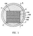
- Figure 1 is a front cross sectional view showing a loose tube paved with a ribbon optical fiber bundle in the prior art
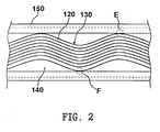
- Figure 2 is a side cross sectional view showing the loose tube as taken along line A-A' of Figure 1.
- the loose tube ribbon optical cable includes: a plurality of optical fibers 120 that coat multifiber cables 110 arrayed in parallel, ribbon optical fiber bundle 130 that are prepared by layering the plural ribbon optical fibers one at a time in order, a loose tube 150 that is paved with the ribbon optical fiber bundle 130, and a jelly 140 that packs the empty space inside of the loose tube 150.
- the ribbon optical fiber bundle 130 is smoothly bent, so as not be arranged in a straight line, along the longitudinal direction of the loose tube 150.
- the reason that the ribbon optical bundle 130 is bent is because the bundle grows longer than the loose tube 150, the the loose tube 150 contracts due to changes in the external environment.
- the ribbon optical fiber bundle 130 in the loose tube 150 can be arranged in spiral lengths as well.
- the four edges (C, D, E and F) of the ribbon optical fiber bundle 130 are adhered closely to the inner wall of the loose tube 150, so the edges (C, D, E and F) of the ribbon optical fiber bundle 130 are subjected to a compressive force.
- This compressive force is proportional to the lay ratio of the ribbon optical fiber bundle 130, while inversely proportional to a clearance inside of the loose tube 150.
- Such compressive force can cause microbending on the surface of the optical fiber comprising the ribbon optical fiber bundle 130, or even can be caused by flaws on the surface optical fiber. Further, the microbending is a main factor in decreasing optical signals forwarding to the optical fiber 110.
- an object of the present invention to provide a loose tube ribbon optical cable with a smallest diameter to prevent the microbending of edges of a ribbon optical fiber bundle.
- a loose tube ribbon optical cable which includes at least one reinforced ribbon optical fiber bundle that comprising a multifiber cable arrayed in parallel, a ribbon optical fiber bundle formed of multi-layered ribbon optical fibers for coating the multifiber cable, and a pair of reinforcing layers with both edges bent towards the outer ribbon optical fiber bundle, being formed on the outside of the bundle; at least one loose tube packed with the reinforced ribbon optical fiber bundle; and an outer coating disposed in a peripheral of the ribbon optical cable, enclosing the loose tube(s).
- Figure 3 is a front cross sectional view illustrating a stiffed ribbon optical fiber bundle in accordance with a preferred embodiment of the present invention
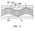
- Figure 4 is a side cross sectional view illustrating of the loose tube as taken along line B-B' of Figure 3.
- the reinforced ribbon optical fiber bundle 250 includes a ribbon optical fiber bundle 230 with multilayered ribbon optical fibers 220 that coat 12-fiber cables 210 with a ultraviolet curable resin, and a pair of reinforcing layers 240 disposed at a upper portion and a lower portion of the ribbon optical fiber bundle 230.
- the ultraviolet curable resin is first coated with the optical fibers 210 at a liquid phase, and later cured when it is irradiated by ultraviolet light.
- the reinforcing layer 240 preferably has the equivalent elastic modulus to that of the ribbon optical fiber 220 by way of assuring that the reinforcing layer 240 and the ribbon optical fiber bundle 250 similarly react to any outer changes, such as temperature change or physical force.
- the reinforcing layer 240 can successfully prevent interfacial separation, cleavage or microbending.
- the edge of the reinforcing layer 240 preferably has the equivalent curvature to that of the inner wall of the loose tube 270. In this way, the clearance of the reinforced ribbon optical fiber bundle 250 can be minimized, and the compressive force applied on the contact area between the loose tube's inner wall and the reinforced layer can be efficiently absorbed thanks to the expanded the contact area.
- a preferable material for the reinforcing layer 240 is selected from a group consisting of fiberglass reinforced plastic, glass steel, plastic and so forth.
- the empty space inside of the loose tube 270 is packed with jelly 260, where the jelly 260 absorbs moisture permeated into the loose tube 270, and absorbs the impact or shock from the outside.
- a strand-form swellable yarn (not shown) that is known to swell when absorbing moisture can be used, instead of the jelly 260.
- the four edges (G, H, I and K) of the reinforced ribbon optical fiber bundle 250 receive the compressive force as they get adhered closely to the inner wall of the loose tube 270.
- the reinforcing layer 240 absorbs the compressive force applied, which consequently minimizes the force to be transmitted to the ribbon optical fiber bundle 230.
- Figure 5 is a cross sectional view illustrating a loose tube ribbon optical cable according to a preferred embodiment of the present invention.
- the loose tube ribbon optical cable includes a reinforced ribbon optical fiber bundle 350, a loose tube 370 for packing the reinforced ribbon optical fiber bundle 350, a jelly for filling the empty space inside of the loose tube 370, a waterproof tape 380 for enclosing the peripheral side of the loose tube 370, an outer coating 390 disposed at a peripheral of the loose tube ribbon optical cable, and a pair of tension lines 400 inserted along the longitudinal direction of the outer coating 390.
- the reinforced ribbon optical fiber bundle 350 includes the matrix structured ribbon optical fiber bundle 330 with multilayered ribbon optical fibers that coat 12-fiber cables 310 arrayed in parallel with a ultraviolet curable resin, and a pair of reinforcing layers 340 disposed at a upper portion and a lower portion of the ribbon optical fiber bundle 330.
- the jelly 360 protects the reinforced ribbon optical fiber bundle 350 from external shocks, and absorbs moisture permeated into the loose tube 370.
- the waterproof tape 380 has a function of absorbing the permeated moisture into the outer coating 390.
- a metallic tape can be used instead of the waterproof tape 380 for protecting the outer coating from any rodent attacks.
- the pair of tension lines 400 is arrayed around the loose tube 370 to be symmetrical to each other.
- the tension lines provide anti-tension against the outer tension, and improve the mechanical strength of the loose tube ribbon optical cable.
- Figure 6 is a cross sectional view illustrating a loose tube ribbon optical cable in accordance with another preferred embodiment of the present invention.
- the loose tube ribbon optical cable includes a central tension line 510, a plurality of loose tubes 550, a binder 560, and an auxiliary tension bar 570, and an outer coating 580.
- the central tension line 510 provides for the loose tube ribbon optical cable the anti-tension, and thus it is located at the center of the cable.
- a fiberglass reinforced plastic (FRP) is typically used.
- FRP fiberglass reinforced plastic
- a polymer such as polyvinyl chloride (PVC) or polyethylene (PE) is often used.
- the loose tube 550 packs the reinforced ribbon optical fiber bundle 530.
- the reinforced ribbon optical bundle 530 includes the matrix structured ribbon optical fiber bundle having multilayered ribbon optical fibers that coat 12-fiber cables with ultraviolet curable resin, and a pair of reinforcing layers disposed at a upper portion and a lower portion of the ribbon optical fiber bundle.
- the empty space inside of the loose tube 550 is packed with jelly 540 that protects the reinforced ribbon optical fiber bundle 530 from the outer shocks, and absorbs moisture permeated into the loose tube 550.
- the binder 560 encompasses the plural loose tube 550, and has a function of maintaining the congregation state of the loose tubes.
- a preferably used material for the binder 560 is selected from a group consisting of aramid yarn, polyester yarn, polyester film and so forth.
- the auxiliary tension bar 570 encloses the binder 560, and has a function of improving the anti-tension of the loose tube ribbon optical cable.
- aramid yarn or glass yarn is used for the auxiliary tension bar.
- the outer coating 580 is positioned at the peripheral of the loose tube ribbon optical cable.
- a polymer such as PVC or PE, which is prepared by an extrusion process.
- the outer coating 580 for the convenience of molting, or unwrapping, can fill a rip cord adjacent to the inner wall.
- the loose tube ribbon optical cable with the reinforced layer can successfully prevent interfacial separation that often occurs to the edges of the ribbon optical fiber bundle, cleavage or microbending in advance.
Landscapes
- Physics & Mathematics (AREA)
- General Physics & Mathematics (AREA)
- Optics & Photonics (AREA)
- Optical Fibers, Optical Fiber Cores, And Optical Fiber Bundles (AREA)
- Light Guides In General And Applications Therefor (AREA)
Applications Claiming Priority (2)
| Application Number | Priority Date | Filing Date | Title |
|---|---|---|---|
| KR2001051943 | 2001-08-28 | ||
| KR10-2001-0051943A KR100396281B1 (ko) | 2001-08-28 | 2001-08-28 | 루즈 튜브 리본 광케이블 |
Publications (3)
| Publication Number | Publication Date |
|---|---|
| EP1288690A2 true EP1288690A2 (de) | 2003-03-05 |
| EP1288690A3 EP1288690A3 (de) | 2004-06-16 |
| EP1288690B1 EP1288690B1 (de) | 2006-05-31 |
Family
ID=36590815
Family Applications (1)
| Application Number | Title | Priority Date | Filing Date |
|---|---|---|---|
| EP02009769A Expired - Lifetime EP1288690B1 (de) | 2001-08-28 | 2002-04-30 | Optisches Hohladerkabel mit Faserbändchen |
Country Status (5)
| Country | Link |
|---|---|
| US (1) | US6687438B2 (de) |
| EP (1) | EP1288690B1 (de) |
| JP (1) | JP3776060B2 (de) |
| KR (1) | KR100396281B1 (de) |
| DE (1) | DE60211817T2 (de) |
Cited By (1)
| Publication number | Priority date | Publication date | Assignee | Title |
|---|---|---|---|---|
| CN108398758A (zh) * | 2018-05-03 | 2018-08-14 | 陕西理工大学 | 一种复合带状光缆 |
Families Citing this family (15)
| Publication number | Priority date | Publication date | Assignee | Title |
|---|---|---|---|---|
| US20070047885A1 (en) * | 2000-11-21 | 2007-03-01 | Yaron Mayer | System and method for transferring much more information in optic fiber cables by significantly increasing the number of fibers per cable |
| US7899290B2 (en) * | 2000-11-21 | 2011-03-01 | Yaron Mayer | System and method for transferring much more information in optic fiber cables by significantly increasing the number of fibers per cable |
| US20040081413A1 (en) * | 2002-10-28 | 2004-04-29 | Bocanegra Luis M. | High fiber density hybrid cable |
| KR100474726B1 (ko) * | 2002-11-07 | 2005-03-11 | 삼성전자주식회사 | 가입자망 광섬유 케이블 |
| KR100526518B1 (ko) * | 2003-07-14 | 2005-11-08 | 삼성전자주식회사 | 옥내용 광섬유 케이블 |
| KR100752856B1 (ko) * | 2005-05-31 | 2007-08-29 | 엘에스전선 주식회사 | 방수스틸테이프를 구비하는 광섬유케이블 |
| KR100708954B1 (ko) * | 2005-06-03 | 2007-04-18 | 엘에스전선 주식회사 | 방수구조가 개선된 광섬유 케이블 |
| CN102023357B (zh) * | 2010-12-31 | 2012-11-07 | 江苏通鼎光电股份有限公司 | 全干式大芯数气吹微缆及光纤束加工方法 |
| CN102023358B (zh) * | 2011-01-20 | 2012-01-18 | 汕头高新区奥星光通信设备有限公司 | 一种引入用皮线光缆 |
| CN104391363A (zh) * | 2014-12-11 | 2015-03-04 | 江苏通鼎光电股份有限公司 | 一种大芯数束状防鼠直埋光缆 |
| CN105044867B (zh) * | 2015-08-12 | 2017-11-17 | 国网山东省电力公司济南供电公司 | 一种自承式8芯皮线光缆 |
| CN105807381A (zh) * | 2016-05-24 | 2016-07-27 | 烽火通信科技股份有限公司 | 一种全干式光纤带松套管及其制作方法 |
| US11803007B2 (en) * | 2019-11-08 | 2023-10-31 | Fujikura Ltd. | Optical fiber |
| US11460632B2 (en) * | 2019-11-08 | 2022-10-04 | Fujikura Ltd. | Optical fiber |
| CN115616718A (zh) * | 2021-07-13 | 2023-01-17 | 江苏中天科技股份有限公司 | 全干式带状光缆、全干式带状光缆的制备方法及其装置 |
Family Cites Families (19)
| Publication number | Priority date | Publication date | Assignee | Title |
|---|---|---|---|---|
| JPS58150905A (ja) * | 1982-03-03 | 1983-09-07 | Nippon Telegr & Teleph Corp <Ntt> | 光ケ−ブルユニツト |
| ZA844474B (en) * | 1983-06-17 | 1985-02-27 | Bicc Plc | Optical fibre ribbon structure |
| JPS63237008A (ja) * | 1987-03-26 | 1988-10-03 | Nippon Telegr & Teleph Corp <Ntt> | 防水形光通信ケ−ブル |
| JPH01150106A (ja) * | 1987-12-08 | 1989-06-13 | Sumitomo Electric Ind Ltd | テープ状光ファイバ心線 |
| US4972041A (en) * | 1989-07-18 | 1990-11-20 | W. L. Gore & Associates, Inc. | Ribbon cables having wrapped drain wires |
| US5229851A (en) * | 1992-04-02 | 1993-07-20 | Pirelli Cable Corporation | Optical fiber cable with large number of ribbon units containing optical fibers and enclosed in tubes |
| JPH06174984A (ja) * | 1992-12-01 | 1994-06-24 | Sumitomo Electric Ind Ltd | 光ケーブル |
| US5481069A (en) * | 1994-01-03 | 1996-01-02 | International Business Machines Corporation | Ribbon cable with terminal edge reinforcement |
| JP3496295B2 (ja) * | 1994-07-01 | 2004-02-09 | 株式会社デンソー | フラットケーブル |
| US5611017A (en) * | 1995-06-01 | 1997-03-11 | Minnesota Mining And Manufacturing Co. | Fiber optic ribbon cable with pre-installed locations for subsequent connectorization |
| KR970066625A (ko) * | 1996-03-20 | 1997-10-13 | 김광호 | 리본 광섬유를 이용한 루즈튜브(loose tube)형 광케이블의 구조 및 제조 방법 |
| US6229944B1 (en) * | 1997-02-04 | 2001-05-08 | Sumitomo Electric Industries, Ltd. | Optical fiber cable |
| KR100360982B1 (ko) * | 1998-12-31 | 2003-01-08 | 주식회사 머큐리 | 리본형광코드및그제조방법 |
| JP2000249881A (ja) * | 1999-02-26 | 2000-09-14 | Fujikura Ltd | 光ファイバケーブルの構造 |
| US6392155B1 (en) * | 1999-05-07 | 2002-05-21 | Hitachi Cable, Ltd. | Flat cable and process for producing the same |
| US6404962B1 (en) * | 1999-09-15 | 2002-06-11 | Fitel Usa Corp. | Groups of optical fibers closely bound by easily removable buffer encasements, and associated fiber optic cables |
| JP2002328277A (ja) * | 2001-04-26 | 2002-11-15 | Fujikura Ltd | 光ケーブル |
| US6600860B2 (en) * | 2001-07-23 | 2003-07-29 | Molex Incorporated | Method of cross-connecting optical fibers |
| US6749446B2 (en) * | 2001-10-10 | 2004-06-15 | Alcatel | Optical fiber cable with cushion members protecting optical fiber ribbon stack |
-
2001
- 2001-08-28 KR KR10-2001-0051943A patent/KR100396281B1/ko not_active Expired - Fee Related
-
2002
- 2002-03-19 US US10/101,253 patent/US6687438B2/en not_active Expired - Fee Related
- 2002-04-30 DE DE60211817T patent/DE60211817T2/de not_active Expired - Fee Related
- 2002-04-30 EP EP02009769A patent/EP1288690B1/de not_active Expired - Lifetime
- 2002-06-28 JP JP2002190864A patent/JP3776060B2/ja not_active Expired - Fee Related
Cited By (2)
| Publication number | Priority date | Publication date | Assignee | Title |
|---|---|---|---|---|
| CN108398758A (zh) * | 2018-05-03 | 2018-08-14 | 陕西理工大学 | 一种复合带状光缆 |
| CN108398758B (zh) * | 2018-05-03 | 2024-04-16 | 西安西古光通信有限公司 | 一种复合带状光缆 |
Also Published As
| Publication number | Publication date |
|---|---|
| DE60211817T2 (de) | 2006-11-30 |
| US6687438B2 (en) | 2004-02-03 |
| JP2003075694A (ja) | 2003-03-12 |
| KR20030018296A (ko) | 2003-03-06 |
| DE60211817D1 (de) | 2006-07-06 |
| KR100396281B1 (ko) | 2003-09-02 |
| US20030044142A1 (en) | 2003-03-06 |
| JP3776060B2 (ja) | 2006-05-17 |
| EP1288690B1 (de) | 2006-05-31 |
| EP1288690A3 (de) | 2004-06-16 |
Similar Documents
| Publication | Publication Date | Title |
|---|---|---|
| US6687438B2 (en) | Loose tube ribbon optical cable | |
| US6259844B1 (en) | Strengthened fiber optic cable | |
| US5109457A (en) | All-dielectric optical fiber cable having enhanced fiber access | |
| EP1011000B1 (de) | Widerstandsfähige optische Faserkabel | |
| US5751880A (en) | Optical unit for an optical fiber telecommunications cable, and an optical fiber cable including such a unit | |
| US6941049B2 (en) | Fiber optic cable having no rigid strength members and a reduced coefficient of thermal expansion | |
| EP1203254B1 (de) | Faseroptisches kabel mit verstärkungselement innerhalb einer äusseren umhüllung | |
| AU2018208727B2 (en) | Fiber optic ribbon | |
| EP2956809B1 (de) | Glasfaserkabelanordnung | |
| US11042000B2 (en) | Optical cable for terrestrial networks | |
| EP1443351A2 (de) | Faseroptisches Kabel mit einem zusammengesetzten Schutzmantel aus Polymer/Metall | |
| US6421487B1 (en) | Reinforced buffered fiber optic ribbon cable | |
| NZ270898A (en) | Optical fibre cable with reinforced buffer tube around fibres | |
| EP1403671B1 (de) | Dielektrisches faseroptisches Kabel mit reduzierter bevorzugter Biegerichtung | |
| EP3884326B1 (de) | Optisches faserkabel mit aufwickelbaren bändern und zentralem stützelement | |
| EP1359448B1 (de) | Optisches Flachbandkabel mit losen Hohladern | |
| US20040190842A1 (en) | Fiber optic assemblies and cables having a security feature | |
| US6963686B2 (en) | Optical fiber cable for air-blown installation | |
| US20240103240A1 (en) | Thin film bundled cable | |
| US6611646B1 (en) | Hybrid strength member for an optical cable | |
| WO2015195095A1 (en) | Central-tube optical-fiber cable | |
| US20060104580A1 (en) | Optical fiber cable | |
| KR100424631B1 (ko) | 리본 광섬유 케이블 | |
| EP2081068B1 (de) | Optisches Kabel | |
| KR20030083859A (ko) | 중심 인장재를 구비한 광섬유 케이블 |
Legal Events
| Date | Code | Title | Description |
|---|---|---|---|
| PUAI | Public reference made under article 153(3) epc to a published international application that has entered the european phase |
Free format text: ORIGINAL CODE: 0009012 |
|
| 17P | Request for examination filed |
Effective date: 20020430 |
|
| AK | Designated contracting states |
Kind code of ref document: A2 Designated state(s): AT BE CH CY DE DK ES FI FR GB GR IE IT LI LU MC NL PT SE TR Designated state(s): AT BE CH CY DE DK ES FI FR GB GR IE IT LI LU MC NL PT SE TR |
|
| AX | Request for extension of the european patent |
Extension state: AL LT LV MK RO SI |
|
| PUAL | Search report despatched |
Free format text: ORIGINAL CODE: 0009013 |
|
| AK | Designated contracting states |
Kind code of ref document: A3 Designated state(s): AT BE CH CY DE DK ES FI FR GB GR IE IT LI LU MC NL PT SE TR |
|
| AX | Request for extension of the european patent |
Extension state: AL LT LV MK RO SI |
|
| 17Q | First examination report despatched |
Effective date: 20040811 |
|
| AKX | Designation fees paid |
Designated state(s): DE FR GB |
|
| GRAP | Despatch of communication of intention to grant a patent |
Free format text: ORIGINAL CODE: EPIDOSNIGR1 |
|
| GRAS | Grant fee paid |
Free format text: ORIGINAL CODE: EPIDOSNIGR3 |
|
| GRAA | (expected) grant |
Free format text: ORIGINAL CODE: 0009210 |
|
| AK | Designated contracting states |
Kind code of ref document: B1 Designated state(s): DE FR GB |
|
| REG | Reference to a national code |
Ref country code: GB Ref legal event code: FG4D |
|
| REF | Corresponds to: |
Ref document number: 60211817 Country of ref document: DE Date of ref document: 20060706 Kind code of ref document: P |
|
| ET | Fr: translation filed | ||
| PLBE | No opposition filed within time limit |
Free format text: ORIGINAL CODE: 0009261 |
|
| STAA | Information on the status of an ep patent application or granted ep patent |
Free format text: STATUS: NO OPPOSITION FILED WITHIN TIME LIMIT |
|
| 26N | No opposition filed |
Effective date: 20070301 |
|
| GBPC | Gb: european patent ceased through non-payment of renewal fee |
Effective date: 20070430 |
|
| PG25 | Lapsed in a contracting state [announced via postgrant information from national office to epo] |
Ref country code: DE Free format text: LAPSE BECAUSE OF NON-PAYMENT OF DUE FEES Effective date: 20071101 |
|
| PG25 | Lapsed in a contracting state [announced via postgrant information from national office to epo] |
Ref country code: GB Free format text: LAPSE BECAUSE OF NON-PAYMENT OF DUE FEES Effective date: 20070430 |
|
| PG25 | Lapsed in a contracting state [announced via postgrant information from national office to epo] |
Ref country code: FR Free format text: LAPSE BECAUSE OF NON-PAYMENT OF DUE FEES Effective date: 20070430 |