EP1288540A1 - Joint à brosse - Google Patents
Joint à brosse Download PDFInfo
- Publication number
- EP1288540A1 EP1288540A1 EP02255956A EP02255956A EP1288540A1 EP 1288540 A1 EP1288540 A1 EP 1288540A1 EP 02255956 A EP02255956 A EP 02255956A EP 02255956 A EP02255956 A EP 02255956A EP 1288540 A1 EP1288540 A1 EP 1288540A1
- Authority
- EP
- European Patent Office
- Prior art keywords
- brush
- seal
- split
- brush seal
- projection
- Prior art date
- Legal status (The legal status is an assumption and is not a legal conclusion. Google has not performed a legal analysis and makes no representation as to the accuracy of the status listed.)
- Granted
Links
Images


Classifications
-
- F—MECHANICAL ENGINEERING; LIGHTING; HEATING; WEAPONS; BLASTING
- F16—ENGINEERING ELEMENTS AND UNITS; GENERAL MEASURES FOR PRODUCING AND MAINTAINING EFFECTIVE FUNCTIONING OF MACHINES OR INSTALLATIONS; THERMAL INSULATION IN GENERAL
- F16J—PISTONS; CYLINDERS; SEALINGS
- F16J15/00—Sealings
- F16J15/16—Sealings between relatively-moving surfaces
- F16J15/32—Sealings between relatively-moving surfaces with elastic sealings, e.g. O-rings
- F16J15/3284—Sealings between relatively-moving surfaces with elastic sealings, e.g. O-rings characterised by their structure; Selection of materials
- F16J15/3292—Lamellar structures
-
- F—MECHANICAL ENGINEERING; LIGHTING; HEATING; WEAPONS; BLASTING
- F16—ENGINEERING ELEMENTS AND UNITS; GENERAL MEASURES FOR PRODUCING AND MAINTAINING EFFECTIVE FUNCTIONING OF MACHINES OR INSTALLATIONS; THERMAL INSULATION IN GENERAL
- F16J—PISTONS; CYLINDERS; SEALINGS
- F16J15/00—Sealings
- F16J15/16—Sealings between relatively-moving surfaces
- F16J15/32—Sealings between relatively-moving surfaces with elastic sealings, e.g. O-rings
- F16J15/3284—Sealings between relatively-moving surfaces with elastic sealings, e.g. O-rings characterised by their structure; Selection of materials
- F16J15/3288—Filamentary structures, e.g. brush seals
Definitions
- the present invention relates to a brush seal device for sealing a clearance formed between a shaft and its mating component that are relatively displaceable. More particularly, the present invention relates to a brush seal device for sealing a clearance formed between two components relatively displaceable, wherein a split brush-seal piece of a thin plate has a brush section on its one side and a base section on the other side and is formed with a projection on its one split face and a recess on its other split face, both the projection and recess being able to engage the corresponding recess and projection on the mating brush-seal pieces, respectively, and a plurality of split brush-seal pieces are connected in order to obtain a brush seal in any size.
- Fig. 14 is a sectional view of a brush seal device 100 mounted between a rotary shaft 120 and a casing 110 through which the rotary shaft 120 passes.
- the rotary shaft 120 and the casing 110 are components of, such as a steam turbine and gas turbine.
- the brush seal device 100 seals fluid by separating the space formed between the casing 110 and the rotary shaft 120 that displace relatively.
- the brush seal device 100 is formed in a ring shape and secured in a channel section 112 of the casing 110.
- the brush seal device 100 has a brush seal 109 to which a backing plate 102 and support plate 103 are attached as its accessories.
- bristles 101 are arranged in a circle to form a wall and coupled together at one end to form an attachment section 104.
- the free end 105 of the brush seal 109 faces the rotary shaft 120.
- the diameter of the bristle 101 used is generally 0.02 to 0.5 mm. Tens or hundreds of thousands of bristles are used for this purpose.
- an annular backing plate 102 On one side face of the brush seal 109 is located an annular backing plate 102 with its side face 108 in contact with the brush seal 109 and supports the bristles 101 against the action of the pressure of the sealed fluid.
- a support plate 103 formed in the shape of a ring plate so as to, in cooperation with the backing plate 102, sandwich the brush seal 109 at its attachment section 104 side.
- the length of the support plate 103 in the radial direction is made small so as to allow the brush seal 109 to be exposed to deform.
- One ends of the backing plate 102, attachment section 104 of the brush seal 109, and support plate 103 are welded together to form a coupling section 106.
- Figs. 15A and B are front views of part of the brush seal 109 shown in Fig. 14.
- the brush seal device 100 in Fig. 15A is in a state that the brush seal 109 and the rotary shaft 120 are normally fit each other such that there occurs no relative oscillation therebetween and the straight bristles 101 are straightly inclined in the rotational direction with respect to the radial direction of the rotary shaft 120.
- the normal state of the brush seal 109 is that the rotary shaft 120 contacts or approximates to the free end 105, as shown by the solid line in Fig. 14.
- the backing plate 102 and the support plate 103 must have a larger thickness for strengthening them in a larger brush seal device 1.
- the yield of material is reduced by the increase of the number of the bristles 101, but also yield of material involved in the number of the backing plates 102 or the support plates 103 that can be cut out from one steel plate is reduced.
- a brush seal device shown in Fig. 16 is another related art of the present invention.
- the leaf device in Fig. 16 has a number of thin plates as a leaf seal 209, that are piled in the circumferential direction of the rotary shaft 120 and seals a high pressure area P1 and a low pressure area P2.
- Outer peripheral of the leaves 209 is brazed to form an attachment section 104 and then mounted in a channel section of a casing 110 through the brazed attachment section 104.
- a backing plate 102 is located on the side face of the leaf seal 209 that faces the low pressure area P2
- a support plate 103 is located on the opposite side face that faces the high pressure area P1, and thus both the plates 102 and 103 support the both side faces of the leaves 209, respectively .
- the pressure of the sealed fluid acts on the brush seal 209 in the direction of the surfaces of the piled thin plates forming the seal 209 and, as the result, gaps between the piled plates are forcedly increased. Accordingly, also in this case, a problem concerning to the capability of preventing the leakage of fluid to be sealed is present.
- the leaf seal 209 forming an annular body includes some hundreds of thousands thin plates used. Therefore, it is extremely difficult to fabricate the leaves 209 and the yield of material is also poor. Further, as the length along the outer circumference of the annular body of the brush seal 209 is longer than that along the inner circumference, spacers are necessarily disposed on the outer circumference to compensate the difference in the circumferential length between the outer and inner circumferences. However, gaps still remain between the surfaces of the piled plates. In this viewpoint, there also exists the problem of sealing ability. Also, as a whole, the leaves 209 constitutes a ring, thereby to cause its elasticity to be lost, so that the flexibility thereof may be reduced and the free end 105 of the leaves 209 be worn quickly.
- the clearance C generated between the free end 105 of the bristles 101, at the position diametrically opposite to the position where the rotary shaft 120 presses against the brush seal 101 becomes larger due to the oscillation of the rotary shaft 120, as shown by phantom line in Fig. 14, which will cause leakage of the sealed fluid though the clearance C.
- the bristles 101 are slanted toward the rotational direction of the rotary shaft.
- the yield of material may become poor, and it may be extremely difficult to fabricate an attachment structure in which bristles 101 are slanted.
- the bristles 101 of steel wire are forcedly separated to each other by the pressure of the sealed fluid, which also present a problem of its sealing ability.
- the thin plates forming the leaf seal 209 are layered one by one along the circumference of the rotary shaft 120, resulting in a large number of thin plates being required and yield of material being reduced. Further, the increase of material will adversely reduce the flexibility and the wear on the leaves 209 is therefore accelerated by the friction generated at the tip of the leaf seal 209.
- the present invention has been made in consideration of the problems as described above, and therefore the technical problem is to enable the production of a brush seal having smaller parts of material regardless of its size, so that yield of material can be improved. Also, it is an object of the present invention to achieve to manufacture brush seals easier, so that production equipment cost can be reduced.
- the present invention has been made to solve the problems as described above, and technical means for solving the problems are constituted as described hereinafter.
- the brush seal device of a preferred embodiment according to the present invention is one mounted on one of two components that are relatively rotated, for sealing the clearance given between the two components, comprising:
- the brush seal is divided into a number of split brush-seal pieces and each of the split brush-seal pieces has a projection and a recess in its both split surfaces, so that it is easy to position and assembly and the binding forces at the engagement section are strong.
- the split brush-seal piece is small even if a brush seal device is larger, and therefore a number of split brush-seal pieces can be obtained from a thin plate, resulting in the improvement of the yield of material.
- the attachment section of the brush seal is formed in the base section of a thin plate, the assembly work for stacking is facilitated in assembling the brush seal device.
- the bristles on one side of a thin plate are formed in the shape of strips, so that the bristles integral with the attachment section is easily attached, and the plate-like bristles have effective ability to seal.
- a number of split brush-seal pieces can be produced from a thin steel plate by etching process or the like, so that machining or processing is easy to perform, and equipment cost can be reduced.
- Fig. 1 is a sectional view, showing in half the first preferred embodiment, in which a brush seal device 1 used in a gas turbine device separates the clearance between the bore of a casing 50 and a rotor 60 inserted therein to divide into a high pressure area P1 and a low pressure area P2.
- the reference numeral 1 denotes a brush seal device.
- a fixing section 20 on the outer circumference side of the brush seal device 1 is mounted, through a snap ring 12, on a step 51 in the inner circumference of the casing 50 which is the other component of the two components.
- the fixing section 20 may be mounted to a channel section 51 defined by in an assembled structure.
- the free end portion 5 at the inner circumference side of the brush seal device 1 is arranged to face the outer circumference of the rotor 60 as the other component, in contact therewith or close thereto.
- the fluid in the high pressure area P1 is sealed by the brush seal device 1.
- a brush seal 2 is the main component, while a backing plate 6 and a support section 10 are accessories.
- the brush seal 2 as shown in Figs.1 and 2 is constituted with a plurality of brush seal units (brush seal unit plate) 2P piled or stacked to form a wall.
- the brush seal unit at its inner side is formed with strips that are slanted toward the rotational direction of the rotor 60, shown as a brush section 2A.
- the base section 2B at its outer side defines an attachment section 3.
- the brush section 2A is formed into brushes 8 constituted with a number of strips formed such that an annular thin plate has thin strips at its inner side and each strip has a square or rectangular shape in cross section. Also, outer circumference end portions of the strips are welded or press-welded together to form an attachment section 3.
- Fig. 2 shows a plan view of a brush seal device 1 in Fig. 1.
- the brush seal 2 is composed of a plurality of stacked and integrated brush seal units 2P in the first embodiment, as shown in Fig. 3.
- the brush seal unit 2P is formed as an annular plate made from a thin plate, as shown in Fig. 3.
- the brush seal unit 2P at its inner circumference side is formed into a number of brushes 8 as strip like bristles to define a brush section 2A.
- the brush seal unit 2P at its outer circumference side is formed as a base section 2B on the thin plate.
- the brush seal unit plate 2P is equally divided along its circumference direction.
- the divided split brush-seal piece (also referred to as a module plate) 4 is in the shape as shown in Fig. 4 which is a plan view of the split brush-seal piece 4.
- a circular recess 12A is formed on a divided face 11 of base section 2B constituting the attachment section 3 of the split brush-seal piece 4.
- a projection 12B having a projecting circular shape is formed on the other divided face 11 of the base section 2B.
- the recess 12A and the projection 12B are formed such that they fit each other, and the combined projection and recess form an engagement portion 12.
- a brush section 2A formed into strips is formed at the inner (inner diameter) side of base section 2B of the split brush-seal piece 4.
- the brush section 2A is slanted toward the rotational direction of a rotor 60.
- the brush section 2A is composed of a number of brushes 8 as bristles having a cross section of a rectangular or quadangle.
- the split brush-seal piece 4 can be easily formed by fine processes, such as etching, wire electric discharging and pressing.
- slits 9 forming triangular spaces are provided on its inner circumference side of an arced thin plate.
- Brushes 8 formed with the slits 9 are formed as plate-like bristles having rectangular (rectangle or square) in cross section, and the dimensions of the cross section in each brush 8 is (0.5-0.005)x(0.5-0.005)mm, preferably (0.20-0.008) x (0.2-0.018) mm.
- the length is 5-50 mm.
- the thickness of the thin plate is 0.5-0.003 mm.
- the thickness of the wall in which the brush seals are stacked 0.5-5 mm or 0.01-0.5mm, depending on the pressure of the sealed fluid.
- the wall herein means a partition formed by stacking the brush seals 2 in the direction of the action of sealed fluid.
- Materials of the brush seal 2 includes, for example, steel, stainless steel, nickel-base alloy and ceramic.
- Fig. 5 is a plan view of the second embodiment of the split brush-seal piece 4.
- the entire structure of the split brush-seal piece 4 is almost the same as that having a shape as shown in Fig. 4.
- a specific difference is a structure of an engagement portion 12.
- the shape of a recess 12A of the engagement portion 12 is that of a recess 12A of Fig. 4 with a notch 12A1, allowing to have elasticity.
- the shape of a projection 12B in the engagement portion 12 is same to that of a projection 12B with a slit 21 in Fig. 4.
- the slit 21 allows the projection 12B to have elasticity.
- Fig. 6 is a plan view of the third embodiment of a split brush-seal piece 4.
- the shape of the projection 12B and its mating recess 12A that constitute the engagement portion 12 is in the shape of an arrow.
- the projection 12B of the engagement portion 12 is formed to project in the shape of a projecting arrow such that it can engage with the recess 12A.
- the engagement portion 12 functions to prevent the split brush-seal pieces 4 mated each other from coming off. It is adopted in a small brush seal device 1.
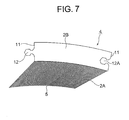
- Fig. 7 is a plan view of the fourth embodiment of the split brush-seal piece 4.
- the shape of the recess 12A of the engagement portion 12 is a hexagon.
- the shape of the projection 12B of the engagement portion 12 is a projecting hexagon such that it can engage with the recess 12A.
- the engagement portion 12 is connected such that the connected split brush-seal pieces 4 do not oscillate each other.
- Fig. 8 is a plan view of the fifth embodiment of a split brush-seal piece 4.
- the split brush-seal piece 4 in Fig. 8 is the one in which the recess 12A of the engagement portion 12 is formed as a recessed circle.
- the projection 12B of the engagement portion 12 is formed in C-shape provided with a slit portion 22 at the base where the recess 12A is engaged.
- the engagement portion 12 is connected such that the split brush-seal pieces 4 are firmly connected.
- Fig. 9 is a plan view of the sixth embodiment of a split brush-seal piece 4.
- the split brush-seal piece 4 in Fig. 9 is the almost the same as the split brush-seal piece 4 in Fig. 8. The difference is that a slit portion 23 forming a C-shaped projection 12B is not located at the root but at the tip.
- the engagement portion 12 in this case functions similarly as in the case in Fig. 8.
- Fig. 10 is a plan view of the seventh embodiment of a split brush-seal piece 4.
- the split brush-seal piece 4 in Fig. 10 is the one in which the recess 12A of the engagement portion 12 is formed in a circle. Also, the projection 12B of the engagement portion 12 is formed in S-shape so as to engage the recess 12A.
- the engagement portion 12 is connected such that the split brush-seal pieces 4 are firmly connected.
- Fig. 11 is a plan view of the eighth embodiment of a split brush-seal piece 4.
- the split brush-seal piece 4 in Fig. 11 is the one in which the recess 12A of the engagement portion 12 is formed in L-shape. Also, the projection 12B of the engagement portion 12 is formed in L-shape such that it engages the recess 12A.
- the engagement portion 12 is connected such that the connected split brush-seal pieces 4 do not come off.
- a brush seal unit 2P By coupling the engagement portions 12 of the split brush-seal pieces 4, a brush seal unit 2P can be assembled.
- the brush seal units 2P are stacked to form a brush seal 2.
- the brush seal 2 is sandwiched at the both sides of the attachment section 3 by a backing plate 6 and a support plate 10 to form a fixing section 20 of the brush seal device 1.
- the backing plate 6 has a fixing section 6A for supporting the attachment portion 3 of the brush seal 2 and a support face 7 for supporting the brush seal 2 against the pressure of the sealed fluid such that the brush seal 2 is not extremely bent.
- the brush seal 2 and the support face 7 may be in contact each other as shown in Fig. 1, or may be separated each other.
- the free end 5 of the brush seal 2 contacts the rotor 60 when the rotor 60 oscillates to a great extent.
- the brush section 2a is composed of a number of fine plate-like brushes 8 having angular cross section, so that their spring constant is small, and it follows elastically in response to the oscillation of the rotor 60 even if it contacts the rotor 60, thereby to prevent the brushes 8 from being worn.
- the brush seal 2 is allowed to deform resiliently, following to the displacement of the rotor 60 even if the brush seal 2 contacts the rotor 60. That is, the contact pressure is relaxed, corresponding to the spring constant preset for the brush seal 2 when the rotor 60 oscillates.
- the angular plate-like brushes 8 of the brush section 8 further decreases the contact pressure, thereby to reduce wearing action.
- the attachment section 3, the backing plate 6 and the support plate section 10 are welded together with electron beam or the like.
- the three-piece welding area defines the fixing section 20.
- the support plate section 10 is formed into a ring shape with the length smaller than that of the backing plate 6 in the radial direction. In Fig. 1, the length of the support section 10 is equal to that of the fixing section 20. The former length may be approximate to that of the backing plate section 6 in the radial direction. In this case, between the brush seal 2 and the side surface of the support section 10 is formed a space into which the sealed fluid flows.
- the material of the backing plate 6 and the support section 10 are made of, for example, nickel base alloy, iron, steel, stainless, or other non-ferrous metal. Various kinds of materials are selected, depending on the type of sealed fluid, temperature or other conditions in application fields.
- Fig. 12 is a plan view of a brush seal unit 2P of a brush seal device 1 according to the second embodiment.
- the brush seal unit 2P is located within a straight space.
- the base section 2B of the brush seal unit 2P is made rectangular, and a recess 12A and a projection 12B are formed on both split surfaces 11, 11 of the base section 2B. By connecting the recesses 12A and the projections 12B to form engagement portions 12 in order, the brush seal unit 2P is completed.
- the brush section 2A of the brush seal unit 2P is slanted toward a row direction, but it is possible not to be slanted, that is, may be extend along the row direction. Other configurations are similar to that of the brush seal unit 2P in Fig. 3.
- Fig. 13 is a plan view, showing to obtain a number of split brush-seal pieces 4 in Fig. 4, from a thin steel plate S.
- 25 split brush-seal pieces 4 can be obtained from a thin plate by etching process.
- the yield of material is increased by taking a number of pieces in this way. This is achieved by providing the engagement portion 12 on the split surfaces 11 of a split brush-seal piece 4.
- the second embodiment of a brush seal device 1 is a brush seal device 1 mounted on one of two components that are relatively rotated, for sealing the clearance given between the two components, comprising:
- a brush seal 2 is divided into a number of split brush-seal pieces 4 and the engagement portions 12 having a projection and a recess are formed on both split faces 11, 11 of respective split brush-seal piece 4, so that positioning and assembly work are easy to perform, and the coupling force at the engagement portion 12 is increased.
- the split brush-seal pieces 4 can be designed to be smaller even if a brush seal device 1 is larger in size, so that a number of split brush-seal pieces 4 can be produced from one thin plate. As the result, the yield of material is improved.
- attachment section 3 of the brush seals 2B is formed at the base section of thin plates, the work to stack them during the assembly operation of the brush seal device 1 is easy.
- brush portion 8 is formed with strips on one side of the thin plate, so that each brush portion 8 integral with the attachment section 3 is easy to be attached, and each of the plate-like brush portions 8 has been improved in sealing ability.
- etching process facilitates to manufacture a number of split brush-seal pieces 4 from one steel plate, and equipment investment cost can be reduced.
- engagement portions 12 of a split brush-seal piece 4 have a projection 12B in a circular shape at one of the split face 11 and a recess 12A in a circular shape at the other split face 11 which engages with a projection 12B of a mating split brush-seal piece 4.
- a brush seal device 1 since the projection and the recess of the engagement portions 12 are formed in a circular shape, two corresponding engagement portions 12 can be easily and firmly engaged by aligning to fit the engagement faces of the corresponding engagement portions 12. Also, it is easy to disengage the engagement portions 12 by the application of force in the direction of the engagement surface onto the projection 12B. Respective brush seals 2 are stacked one by one to easily assemble a device.
- a brush seal device 1 in one split face 11 of a split brush-seal piece 4 is provided a C-shape projection 12B, and in the other split face 11 is provided a circular recess 12A that can engage a projection 12B.
- a brush seal device 1 of the fourth embodiment since the projection 12B of the engagement portion 12 is formed in C-shape, elasticity toward the outer diameter can be effected, and the coupling force can be strengthened.
- annular brush seal 2 is formed by connecting through engagement portions 12 a plurality of split brush-seal pieces 4, each of the inner circumferences of which is generally formed in an arc shape.
- an annular brush seal device 1 can be easily obtained by coupling the engagement portions 12 of split brush-seal pieces 4. Besides, since the split brush-seal pieces 4 can be cut out from a small plate even if the brush seal device 1 is larger, the yield of material is improved.
- a number of split brush-seal pieces can be taken from one steel plate efficiently through etching process or the like, so that production cost can be reduced.
- a brush seal device has a configuration in which a brush seal unit is divided into a number of split brush-seal pieces with a projection and a recess on the both side, so that the coupling force between the split brush-seal pieces is great and easy work to assemble the brush seal device is achieved.
- engagement portions of the split brush-seal pieces are coupled each other to form a brush seal device even if the brush seal device is large in size, a number of small split brush-seal pieces can be cut out from one thin sheet plate, and the yield of material is improved.
Landscapes
- Engineering & Computer Science (AREA)
- General Engineering & Computer Science (AREA)
- Mechanical Engineering (AREA)
- Sealing Devices (AREA)
- Turbine Rotor Nozzle Sealing (AREA)
Applications Claiming Priority (2)
| Application Number | Priority Date | Filing Date | Title |
|---|---|---|---|
| JP2001260129 | 2001-08-29 | ||
| JP2001260129A JP4824225B2 (ja) | 2001-08-29 | 2001-08-29 | 板ブラシシール装置 |
Publications (2)
| Publication Number | Publication Date |
|---|---|
| EP1288540A1 true EP1288540A1 (fr) | 2003-03-05 |
| EP1288540B1 EP1288540B1 (fr) | 2004-06-23 |
Family
ID=19087373
Family Applications (1)
| Application Number | Title | Priority Date | Filing Date |
|---|---|---|---|
| EP02255956A Expired - Lifetime EP1288540B1 (fr) | 2001-08-29 | 2002-08-28 | Joint à brosse |
Country Status (4)
| Country | Link |
|---|---|
| US (1) | US6764078B2 (fr) |
| EP (1) | EP1288540B1 (fr) |
| JP (1) | JP4824225B2 (fr) |
| DE (1) | DE60200663T2 (fr) |
Cited By (5)
| Publication number | Priority date | Publication date | Assignee | Title |
|---|---|---|---|---|
| EP1347217A2 (fr) * | 2002-03-20 | 2003-09-24 | United Technologies Corporation | Joint d'étanchéité à brosse |
| EP1479952A2 (fr) * | 2003-05-21 | 2004-11-24 | Mitsubishi Heavy Industries, Ltd. | Dispositif d'étanchéité pour axe |
| EP1510655A1 (fr) * | 2002-06-13 | 2005-03-02 | General Electric Company | Support de joint à brosse |
| CN100379948C (zh) * | 2003-09-05 | 2008-04-09 | 通用电气公司 | 刷式密封装置的支撑 |
| CN100396885C (zh) * | 2003-05-21 | 2008-06-25 | 三菱重工业株式会社 | 轴密封机构、轴密封机构的组装结构和大型流体机械 |
Families Citing this family (53)
| Publication number | Priority date | Publication date | Assignee | Title |
|---|---|---|---|---|
| JP4081719B2 (ja) * | 2003-05-30 | 2008-04-30 | イーグル・エンジニアリング・エアロスペース株式会社 | 板ブラシシール装置 |
| JP3993536B2 (ja) * | 2003-06-20 | 2007-10-17 | 三菱重工業株式会社 | 軸シールの製造方法、軸シール、軸シール部材及び軸シールを用いた回転機械 |
| JP4677179B2 (ja) * | 2003-08-20 | 2011-04-27 | ゼネラル・エレクトリック・カンパニイ | ブラシシール支持体 |
| US20060249911A1 (en) * | 2005-05-04 | 2006-11-09 | General Electric Company | Abradable and/or abrasive coating and brush seal configuration |
| US7703774B2 (en) * | 2006-09-12 | 2010-04-27 | General Electric Company | Shaft seal using shingle members |
| US7735833B2 (en) * | 2006-11-14 | 2010-06-15 | The University Of Akron | Double padded finger seal |
| WO2009024770A1 (fr) * | 2007-08-22 | 2009-02-26 | Cross Manufacturing Company (1938) Ltd | Perfectionnements aux joints à brosse |
| US20110031704A1 (en) * | 2009-05-15 | 2011-02-10 | Lehr Brian C | Segmented Gaskets |
| US8490981B2 (en) * | 2010-02-23 | 2013-07-23 | General Electric Company | Brush seal |
| US9206904B2 (en) | 2010-07-08 | 2015-12-08 | Siemens Energy, Inc. | Seal including flexible seal strips |
| US8690158B2 (en) * | 2010-07-08 | 2014-04-08 | Siemens Energy, Inc. | Axially angled annular seals |
| US8328198B2 (en) * | 2010-10-06 | 2012-12-11 | General Electric Company | Brush seal |
| US8919633B2 (en) * | 2012-01-04 | 2014-12-30 | General Electric Company | Seal assembly and method for assembling a turbine |
| JP6131530B2 (ja) * | 2012-04-27 | 2017-05-24 | 日本精工株式会社 | リニアガイド装置 |
| US9541006B2 (en) | 2012-12-29 | 2017-01-10 | United Technologies Corporation | Inter-module flow discourager |
| WO2014105619A1 (fr) | 2012-12-29 | 2014-07-03 | United Technologies Corporation | Bossage multifonction pour carter de sortie turbine |
| US9297312B2 (en) | 2012-12-29 | 2016-03-29 | United Technologies Corporation | Circumferentially retained fairing |
| US10240481B2 (en) | 2012-12-29 | 2019-03-26 | United Technologies Corporation | Angled cut to direct radiative heat load |
| US9771818B2 (en) | 2012-12-29 | 2017-09-26 | United Technologies Corporation | Seals for a circumferential stop ring in a turbine exhaust case |
| US9845695B2 (en) | 2012-12-29 | 2017-12-19 | United Technologies Corporation | Gas turbine seal assembly and seal support |
| WO2014105780A1 (fr) | 2012-12-29 | 2014-07-03 | United Technologies Corporation | Ensemble et support de joint de turbine à gaz à usages multiples |
| US10094389B2 (en) | 2012-12-29 | 2018-10-09 | United Technologies Corporation | Flow diverter to redirect secondary flow |
| JP6271582B2 (ja) | 2012-12-29 | 2018-01-31 | ユナイテッド テクノロジーズ コーポレイションUnited Technologies Corporation | ガスタービンシールアセンブリおよびシール支持体 |
| US9850780B2 (en) | 2012-12-29 | 2017-12-26 | United Technologies Corporation | Plate for directing flow and film cooling of components |
| US9903224B2 (en) | 2012-12-29 | 2018-02-27 | United Technologies Corporation | Scupper channelling in gas turbine modules |
| US9850774B2 (en) | 2012-12-29 | 2017-12-26 | United Technologies Corporation | Flow diverter element and assembly |
| US10138742B2 (en) | 2012-12-29 | 2018-11-27 | United Technologies Corporation | Multi-ply finger seal |
| US9631517B2 (en) | 2012-12-29 | 2017-04-25 | United Technologies Corporation | Multi-piece fairing for monolithic turbine exhaust case |
| WO2014105603A1 (fr) | 2012-12-29 | 2014-07-03 | United Technologies Corporation | Bouclier thermique en plusieurs pièces |
| EP2938863B1 (fr) | 2012-12-29 | 2019-09-25 | United Technologies Corporation | Liaison mécanique destinée à un écran thermique segmenté |
| WO2014105602A1 (fr) | 2012-12-29 | 2014-07-03 | United Technologies Corporation | Bouclier thermique pour carter |
| WO2014105657A1 (fr) | 2012-12-29 | 2014-07-03 | United Technologies Corporation | Monture à pattes pouvant être infléchies |
| US9863261B2 (en) | 2012-12-29 | 2018-01-09 | United Technologies Corporation | Component retention with probe |
| US9828867B2 (en) | 2012-12-29 | 2017-11-28 | United Technologies Corporation | Bumper for seals in a turbine exhaust case |
| US9347330B2 (en) | 2012-12-29 | 2016-05-24 | United Technologies Corporation | Finger seal |
| US9206742B2 (en) | 2012-12-29 | 2015-12-08 | United Technologies Corporation | Passages to facilitate a secondary flow between components |
| US10060279B2 (en) | 2012-12-29 | 2018-08-28 | United Technologies Corporation | Seal support disk and assembly |
| WO2014143329A2 (fr) | 2012-12-29 | 2014-09-18 | United Technologies Corporation | Trous de refroidissement pour jonction de châssis |
| WO2014105425A1 (fr) | 2012-12-29 | 2014-07-03 | United Technologies Corporation | Ensemble cadre de turbine et procédé de conception d'ensemble cadre de turbine |
| US10006306B2 (en) | 2012-12-29 | 2018-06-26 | United Technologies Corporation | Turbine exhaust case architecture |
| WO2014105599A1 (fr) | 2012-12-29 | 2014-07-03 | United Technologies Corporation | Bouclier thermique pour le refroidissement d'une entretoise |
| US9562478B2 (en) | 2012-12-29 | 2017-02-07 | United Technologies Corporation | Inter-module finger seal |
| WO2014105682A1 (fr) | 2012-12-31 | 2014-07-03 | United Technologies Corporation | Structure en plusieurs pièces de carter d'échappement de turbine |
| GB2524443B (en) | 2012-12-31 | 2020-02-12 | United Technologies Corp | Turbine exhaust case multi-piece frame |
| US9890663B2 (en) | 2012-12-31 | 2018-02-13 | United Technologies Corporation | Turbine exhaust case multi-piece frame |
| EP2971579B1 (fr) | 2013-03-11 | 2020-04-29 | United Technologies Corporation | Sous-ensemble arrière pour un carénage de carter d'échappement de turbine |
| KR101458984B1 (ko) | 2013-11-26 | 2014-11-07 | 박모세 | 브러시 시일 제조를 위한 지그 |
| US9587505B2 (en) | 2013-12-05 | 2017-03-07 | General Electric Company | L brush seal for turbomachinery application |
| US9322287B2 (en) | 2014-06-03 | 2016-04-26 | General Electric Company | Brush seal for turbine |
| US20170051983A1 (en) * | 2015-08-18 | 2017-02-23 | Arvos Inc. | Flexible seal for a rotary regenerative preheater |
| US10247106B2 (en) * | 2016-06-15 | 2019-04-02 | General Electric Company | Method and system for rotating air seal with integral flexible heat shield |
| US10364748B2 (en) | 2016-08-19 | 2019-07-30 | United Technologies Corporation | Finger seal flow metering |
| GB202203012D0 (en) * | 2022-03-04 | 2022-04-20 | Rolls Royce Plc | Brush seal |
Citations (3)
| Publication number | Priority date | Publication date | Assignee | Title |
|---|---|---|---|---|
| US5265412A (en) * | 1992-07-28 | 1993-11-30 | General Electric Company | Self-accommodating brush seal for gas turbine combustor |
| US5316318A (en) * | 1992-04-23 | 1994-05-31 | Societe Nationale D'etude Et De Construction De Moteurs D'aviation "Snecma" | Annular brush gasket |
| EP1013975A1 (fr) * | 1998-07-13 | 2000-06-28 | Mitsubishi Heavy Industries, Ltd. | Joint d'arbre et turbine utilisant ce joint |
Family Cites Families (13)
| Publication number | Priority date | Publication date | Assignee | Title |
|---|---|---|---|---|
| US3124502A (en) * | 1964-03-10 | Composite fibrous lubricant packing | ||
| US1045088A (en) * | 1912-02-28 | 1912-11-19 | George E Wriedt | Packing. |
| US1809056A (en) * | 1922-09-04 | 1931-06-09 | Mellor John | Metallic packing |
| US1967573A (en) * | 1932-12-08 | 1934-07-24 | Garlock Packing Co | Sectional machinery packing |
| US5031922A (en) * | 1989-12-21 | 1991-07-16 | Allied-Signal Inc. | Bidirectional finger seal |
| US5071138A (en) * | 1989-12-21 | 1991-12-10 | Allied-Signal Inc. | Laminated finger seal |
| US5042823A (en) * | 1989-12-21 | 1991-08-27 | Allied-Signal Inc. | Laminated finger seal |
| US5176389A (en) * | 1991-02-21 | 1993-01-05 | United Technologies | Segmented brush seal |
| US5108116A (en) * | 1991-05-31 | 1992-04-28 | Allied-Signal Inc. | Laminated finger seal with logarithmic curvature |
| JPH11247995A (ja) * | 1998-03-03 | 1999-09-14 | Marusan:Kk | 連結型ガスケット |
| JP2000018385A (ja) * | 1998-04-28 | 2000-01-18 | Nok Corp | 分割型ブーツ |
| JP2002081552A (ja) * | 2000-09-04 | 2002-03-22 | Toshiba Corp | ブラシシール装置 |
| US6431550B1 (en) * | 2000-09-25 | 2002-08-13 | General Electric Company | Hydrogen seal ring having seal at ring intersegment |
-
2001
- 2001-08-29 JP JP2001260129A patent/JP4824225B2/ja not_active Expired - Lifetime
-
2002
- 2002-06-18 US US10/173,260 patent/US6764078B2/en not_active Expired - Lifetime
- 2002-08-28 EP EP02255956A patent/EP1288540B1/fr not_active Expired - Lifetime
- 2002-08-28 DE DE60200663T patent/DE60200663T2/de not_active Expired - Lifetime
Patent Citations (3)
| Publication number | Priority date | Publication date | Assignee | Title |
|---|---|---|---|---|
| US5316318A (en) * | 1992-04-23 | 1994-05-31 | Societe Nationale D'etude Et De Construction De Moteurs D'aviation "Snecma" | Annular brush gasket |
| US5265412A (en) * | 1992-07-28 | 1993-11-30 | General Electric Company | Self-accommodating brush seal for gas turbine combustor |
| EP1013975A1 (fr) * | 1998-07-13 | 2000-06-28 | Mitsubishi Heavy Industries, Ltd. | Joint d'arbre et turbine utilisant ce joint |
Cited By (10)
| Publication number | Priority date | Publication date | Assignee | Title |
|---|---|---|---|---|
| EP1347217A2 (fr) * | 2002-03-20 | 2003-09-24 | United Technologies Corporation | Joint d'étanchéité à brosse |
| EP1347217A3 (fr) * | 2002-03-20 | 2004-02-18 | United Technologies Corporation | Joint d'étanchéité à brosse |
| US6996885B2 (en) | 2002-03-20 | 2006-02-14 | United Technologies Corporation | Method of making bristle arrangement for brush seal |
| EP1510655A1 (fr) * | 2002-06-13 | 2005-03-02 | General Electric Company | Support de joint à brosse |
| EP1479952A2 (fr) * | 2003-05-21 | 2004-11-24 | Mitsubishi Heavy Industries, Ltd. | Dispositif d'étanchéité pour axe |
| EP1479952A3 (fr) * | 2003-05-21 | 2004-12-01 | Mitsubishi Heavy Industries, Ltd. | Dispositif d'étanchéité pour axe |
| CN1324221C (zh) * | 2003-05-21 | 2007-07-04 | 三菱重工业株式会社 | 轴密封机构 |
| US7364165B2 (en) | 2003-05-21 | 2008-04-29 | Mitsubishi Heavy Industries, Ltd. | Shaft seal mechanism |
| CN100396885C (zh) * | 2003-05-21 | 2008-06-25 | 三菱重工业株式会社 | 轴密封机构、轴密封机构的组装结构和大型流体机械 |
| CN100379948C (zh) * | 2003-09-05 | 2008-04-09 | 通用电气公司 | 刷式密封装置的支撑 |
Also Published As
| Publication number | Publication date |
|---|---|
| EP1288540B1 (fr) | 2004-06-23 |
| DE60200663T2 (de) | 2005-07-07 |
| US6764078B2 (en) | 2004-07-20 |
| JP4824225B2 (ja) | 2011-11-30 |
| JP2003065442A (ja) | 2003-03-05 |
| US20030042682A1 (en) | 2003-03-06 |
| DE60200663D1 (de) | 2004-07-29 |
Similar Documents
| Publication | Publication Date | Title |
|---|---|---|
| EP1288540B1 (fr) | Joint à brosse | |
| US6805356B2 (en) | Brush seal and brush seal device | |
| EP1365181B1 (fr) | Joint brosses constitué de feuilles | |
| EP1271021B1 (fr) | Joint en brosse | |
| US6733014B2 (en) | Brush seal | |
| EP1482220B1 (fr) | Joint à brosse à structure lamellaire | |
| US6550777B2 (en) | Split packing ring segment for a brush seal insert in a rotary machine | |
| US6648334B2 (en) | Brush seal device | |
| US6874787B2 (en) | Brush seal device | |
| CN112020620B (zh) | 密封装置 | |
| JP4157282B2 (ja) | ブラシシール装置 | |
| JP2011094803A (ja) | 板ブラシシール装置 | |
| JP2003106458A (ja) | 板ブラシシール | |
| JP4824207B2 (ja) | 板ブラシシール装置 | |
| JP4227361B2 (ja) | 板ブラシシール | |
| JP4764566B2 (ja) | 板ブラシシール装置 | |
| JP3986518B2 (ja) | 軸シール機構 | |
| JP4727867B2 (ja) | ブラシシール装置 | |
| JP2004084690A (ja) | 板ブラシシール単板の製造方法 | |
| JP2004116589A (ja) | 板ブラシシール装置 |
Legal Events
| Date | Code | Title | Description |
|---|---|---|---|
| PUAI | Public reference made under article 153(3) epc to a published international application that has entered the european phase |
Free format text: ORIGINAL CODE: 0009012 |
|
| AK | Designated contracting states |
Kind code of ref document: A1 Designated state(s): AT BE BG CH CY CZ DE DK EE ES FI FR GB GR IE IT LI LU MC NL PT SE SK TR Designated state(s): AT BE BG CH CY CZ DE DK EE ES FI FR GB GR IE IT LI LU MC NL PT SE SK TR |
|
| AX | Request for extension of the european patent |
Extension state: AL LT LV MK RO SI |
|
| 17P | Request for examination filed |
Effective date: 20030814 |
|
| GRAP | Despatch of communication of intention to grant a patent |
Free format text: ORIGINAL CODE: EPIDOSNIGR1 |
|
| AKX | Designation fees paid |
Designated state(s): DE FR GB IT |
|
| GRAS | Grant fee paid |
Free format text: ORIGINAL CODE: EPIDOSNIGR3 |
|
| GRAA | (expected) grant |
Free format text: ORIGINAL CODE: 0009210 |
|
| AK | Designated contracting states |
Kind code of ref document: B1 Designated state(s): DE FR GB IT |
|
| REG | Reference to a national code |
Ref country code: GB Ref legal event code: FG4D |
|
| REG | Reference to a national code |
Ref country code: IE Ref legal event code: FG4D |
|
| REF | Corresponds to: |
Ref document number: 60200663 Country of ref document: DE Date of ref document: 20040729 Kind code of ref document: P |
|
| ET | Fr: translation filed | ||
| PLBE | No opposition filed within time limit |
Free format text: ORIGINAL CODE: 0009261 |
|
| STAA | Information on the status of an ep patent application or granted ep patent |
Free format text: STATUS: NO OPPOSITION FILED WITHIN TIME LIMIT |
|
| REG | Reference to a national code |
Ref country code: IE Ref legal event code: MM4A |
|
| 26N | No opposition filed |
Effective date: 20050324 |
|
| PGFP | Annual fee paid to national office [announced via postgrant information from national office to epo] |
Ref country code: FR Payment date: 20080730 Year of fee payment: 7 Ref country code: IT Payment date: 20080828 Year of fee payment: 7 |
|
| REG | Reference to a national code |
Ref country code: FR Ref legal event code: ST Effective date: 20100430 |
|
| PG25 | Lapsed in a contracting state [announced via postgrant information from national office to epo] |
Ref country code: FR Free format text: LAPSE BECAUSE OF NON-PAYMENT OF DUE FEES Effective date: 20090831 |
|
| PG25 | Lapsed in a contracting state [announced via postgrant information from national office to epo] |
Ref country code: IT Free format text: LAPSE BECAUSE OF NON-PAYMENT OF DUE FEES Effective date: 20090828 |
|
| PGFP | Annual fee paid to national office [announced via postgrant information from national office to epo] |
Ref country code: GB Payment date: 20200819 Year of fee payment: 19 Ref country code: DE Payment date: 20200819 Year of fee payment: 19 |
|
| REG | Reference to a national code |
Ref country code: DE Ref legal event code: R119 Ref document number: 60200663 Country of ref document: DE |
|
| GBPC | Gb: european patent ceased through non-payment of renewal fee |
Effective date: 20210828 |
|
| PG25 | Lapsed in a contracting state [announced via postgrant information from national office to epo] |
Ref country code: GB Free format text: LAPSE BECAUSE OF NON-PAYMENT OF DUE FEES Effective date: 20210828 Ref country code: DE Free format text: LAPSE BECAUSE OF NON-PAYMENT OF DUE FEES Effective date: 20220301 |