EP1288173A1 - Vorrichtung zum Auftragen von Schutzflüssigkeit auf Glas - Google Patents
Vorrichtung zum Auftragen von Schutzflüssigkeit auf Glas Download PDFInfo
- Publication number
- EP1288173A1 EP1288173A1 EP02018316A EP02018316A EP1288173A1 EP 1288173 A1 EP1288173 A1 EP 1288173A1 EP 02018316 A EP02018316 A EP 02018316A EP 02018316 A EP02018316 A EP 02018316A EP 1288173 A1 EP1288173 A1 EP 1288173A1
- Authority
- EP
- European Patent Office
- Prior art keywords
- roller
- bearing
- connecting shaft
- bodies
- support strut
- Prior art date
- Legal status (The legal status is an assumption and is not a legal conclusion. Google has not performed a legal analysis and makes no representation as to the accuracy of the status listed.)
- Granted
Links
Images
Classifications
-
- C—CHEMISTRY; METALLURGY
- C03—GLASS; MINERAL OR SLAG WOOL
- C03C—CHEMICAL COMPOSITION OF GLASSES, GLAZES OR VITREOUS ENAMELS; SURFACE TREATMENT OF GLASS; SURFACE TREATMENT OF FIBRES OR FILAMENTS MADE FROM GLASS, MINERALS OR SLAGS; JOINING GLASS TO GLASS OR OTHER MATERIALS
- C03C17/00—Surface treatment of glass, not in the form of fibres or filaments, by coating
- C03C17/001—General methods for coating; Devices therefor
- C03C17/002—General methods for coating; Devices therefor for flat glass, e.g. float glass
-
- B—PERFORMING OPERATIONS; TRANSPORTING
- B05—SPRAYING OR ATOMISING IN GENERAL; APPLYING FLUENT MATERIALS TO SURFACES, IN GENERAL
- B05B—SPRAYING APPARATUS; ATOMISING APPARATUS; NOZZLES
- B05B3/00—Spraying or sprinkling apparatus with moving outlet elements or moving deflecting elements
- B05B3/02—Spraying or sprinkling apparatus with moving outlet elements or moving deflecting elements with rotating elements
- B05B3/10—Spraying or sprinkling apparatus with moving outlet elements or moving deflecting elements with rotating elements discharging over substantially the whole periphery of the rotating member
- B05B3/1007—Spraying or sprinkling apparatus with moving outlet elements or moving deflecting elements with rotating elements discharging over substantially the whole periphery of the rotating member characterised by the rotating member
Definitions
- the invention relates to a device for applying a protective liquid on glass with a direction transverse to the transport direction of the glass plates or bands arranged, partially in a trough containing the protective liquid submerged roller used for centrifuging liquid droplets the guided glass plates or belts is driven in rotation.
- the invention is based on the object, a generic device for applying protective fluid to wide glass plates or bands create, which has a simple, space-saving design.
- roller of several rotatably interconnected roller sub-bodies is set together between the roller sub-bodies each one carried by a support strut Roller bearing is arranged and the roller body part sleeve-shaped, the Have roller bearing encompassing approaches whose outer surfaces with the outer surfaces of the roller part body are aligned and up to the Extending support strut.
- each roller bearing between two partial roller bodies one carried by the support strut Bearing sleeve, in which a connecting shaft against axial Verschschschlingung is secured, at the ends in holes in the end faces of Roller part body engaging dowels are mounted. This will be in easy way without screwing secured against rotation Created connection between two partial roller bodies.
- the connecting shaft has a central part larger Diameter on, on both sides of the inner bearing shells of two Rolling bears and the inner bearing shells on the side panels of Connecting shaft sit while the outer bearing shells in the bearing sleeve are used.
- a ring is placed on each side part of the connecting shaft, the axial bores for receiving the one ends of the dowel pins and a continuous radial bore for receiving a side part and the Having two dowels penetrating fixing pin.
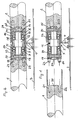
- the Support strut 4 is fixed, e.g. by welding, with a total of 5 designated bearing sleeve connected.
- the bearing sleeve 5 has a middle Section 6 with a smaller inner diameter and two lateral sections 7, 8 with a larger inner diameter.
- In the side sections 7, 8 is each a rolling bearing 9, 10 used.
- the bearings are used to store a total with 11 designated connecting shaft.
- the connecting shaft 11 has a middle part 12 of larger outer diameter and two side parts 13, 14 of smaller outer diameter.
- the inner bearing shells 15, 16 of the Rolling 9, 10 applied in such a way that they simultaneously on the end faces abut the middle part 12.
- the outer bearings 17, 18 are in the lateral sections 7, 8 of the bearing sleeve 5 is inserted and supported in axial direction at the end faces of the karren portion 6 of the bearing sleeve 5 off. These parts form the roller bearing.
- Each ring 19, 20 has a continuous radial bore and two axial holes that expediently offset by 180 ° from each other are on.
- the radial bore is aligned with a corresponding hole in the side part 13 and 14.
- Each axial bore may have a dowel pin 23, 24th or 25, 26 record.
- Each dowel 23 to 26 also has a radial Hole on.
- the Dowel pins z. B. 23, 24 can in axial bores 21, 22 in the Roller partial bodies, e.g. 1 are introduced, as Figure 1 shows. she then connect the roller part body 1, 2 via the connecting shaft 11th together. Furthermore, at the end faces of the side parts 13, 14 of the Connecting shaft 11 centering lugs e.g. 29 be provided at the Assembly into corresponding wells, e.g. 30 in the front ends of the Roll part body 1, 2 enter.
- the roller part body 1, 2 are provided with sleeve-shaped projections 31, 32, their outer surfaces with the outer surfaces of the roller body part 1, second aligned.
- the lugs 31, 32 extend in the assembled state all parts up to the support strut 4.
- the from the roller body part 1, 2 composite roller therefore has a largely continuous, only interrupted by very narrow slits in the region of the support struts 4 External surface, which does not respond to a uniform moistening of the glass to interfere. In the same way, more than two Roll part bodies are assembled.
Landscapes
- Chemical & Material Sciences (AREA)
- Life Sciences & Earth Sciences (AREA)
- Engineering & Computer Science (AREA)
- Chemical Kinetics & Catalysis (AREA)
- General Chemical & Material Sciences (AREA)
- Geochemistry & Mineralogy (AREA)
- Materials Engineering (AREA)
- Organic Chemistry (AREA)
- Rollers For Roller Conveyors For Transfer (AREA)
- Coating Apparatus (AREA)
Abstract
Description
- Fig. 1
- einen Längsschnitt durch die wesentlichen Teiel einer Welle beim Zusammenbau und
- Fig.2
- eine der Figur 1 entsprechende Darstellung nach dem Zusammenbau.
Claims (4)
- Vorrichtung zum Auftragen einer Schutzflüssigkeit auf Glas mit einer quer zur Transportrichtung der Glasplatten oder -bänder angeordneten, teilweise in eine die Schutzflüssigkeit enthaltende Wanne eintauchende Walze, die zum Abschleudern von Flüssigkeitströpfchen auf die darunter geführten Glasplatten oder -bänder rotierend angetrieben ist, dadurch gekennzeichnet, dass dass die Walze aus mehreren drehfest miteinander verbundenen Walzenteilkörpern (1, 2) zusammen gesetzt ist, zwischen den Walzenteilkörpern (1, 2) jeweils eine von einer Tragstrebe (4) getragene Walzenlagerung angeordnet ist und die Walzenteilkörper (1, 2) hülsenförmige, die Walzenlagerung umgreifende Ansätze (31, 32) aufweisen, deren Außenflächen mit den Außenflächen der Walzenteilkörper (1, 2) fluchten sowie sich bis zur Tragstrebe (4) erstrecken.
- Vorrichtung nach Anspruch 1, dadurch gekennzeichnet, dass jede Walzenlagerung zwischen zwei Walzenteilkörpern (1, 2) eine von der Tragstrebe (4) getragene Lagerhülse (5) aufweist, in der eine Verbindungswelle (11) gegen axiale Verschliebung gesichert gelagert ist, an deren Enden in Bohrungen in den Stirnseiten der Walzenteilkörper (1, 2) eingreifende Paßstifte (23 bis 26) angebracht sind.
- Vorrichtung nach Ansurch 2, dadurch gekennzeichnet, dass die Verbindungswelle (11) einen Mittelteil (12) größeren Durchmessers aufweist, der beidseitig an den inneren Lagerschalen (15, 16) zweier Wälzlager (9, 10) anliegt und die inneren Lagerschalen (15, 16) auf den Seitenteilen (13, 14) der Verbindungswelle (11) sitzen während die äußeren Lagerschalen (17, 18) in die Lagerhülse (5) eingesetzt sind.
- Vorrichtung nach Anspruch 2 oder 3, dadurch gekennzeichnet, dass auf jeden Seitenteil (13, 14) der Verbindungswelle (11) ein Ring (19, 20) aufgesetzt ist, der axiale Bohrungen zur Aufnahme der einen Enden der Paßstifte (23 bis 26) und eine durchlaufende radiale Bohrung zur Aufnahme eines den Seitenteil (13 bzw. 14) und die beiden Paßstifte (23, 24 bzw. 25, 26) durchsetzenden Fixierstiftes (27 bzw. 28) aufweist.
Applications Claiming Priority (2)
| Application Number | Priority Date | Filing Date | Title |
|---|---|---|---|
| DE20114332U DE20114332U1 (de) | 2001-08-30 | 2001-08-30 | Vorrichtung zum Auftragen von Schutzflüssigkeit auf Glas |
| DE20114332U | 2001-08-30 |
Publications (2)
| Publication Number | Publication Date |
|---|---|
| EP1288173A1 true EP1288173A1 (de) | 2003-03-05 |
| EP1288173B1 EP1288173B1 (de) | 2005-01-19 |
Family
ID=7961134
Family Applications (1)
| Application Number | Title | Priority Date | Filing Date |
|---|---|---|---|
| EP02018316A Expired - Lifetime EP1288173B1 (de) | 2001-08-30 | 2002-08-14 | Vorrichtung zum Auftragen von Schutzflüssigkeit auf Glas |
Country Status (2)
| Country | Link |
|---|---|
| EP (1) | EP1288173B1 (de) |
| DE (2) | DE20114332U1 (de) |
Citations (2)
| Publication number | Priority date | Publication date | Assignee | Title |
|---|---|---|---|---|
| DE19500967A1 (de) * | 1995-01-14 | 1996-07-18 | Schaaff & Meurer Gmbh | Vorrichtung zum Aufbringen von Flüssigkeitsfilmen |
| DE19707031A1 (de) | 1997-02-21 | 1998-08-27 | Werner Kotterer | Vorrichtung zum Auftragen einer Schutzflüssigkeit auf Glas |
-
2001
- 2001-08-30 DE DE20114332U patent/DE20114332U1/de not_active Expired - Lifetime
-
2002
- 2002-08-14 EP EP02018316A patent/EP1288173B1/de not_active Expired - Lifetime
- 2002-08-14 DE DE50202032T patent/DE50202032D1/de not_active Expired - Lifetime
Patent Citations (2)
| Publication number | Priority date | Publication date | Assignee | Title |
|---|---|---|---|---|
| DE19500967A1 (de) * | 1995-01-14 | 1996-07-18 | Schaaff & Meurer Gmbh | Vorrichtung zum Aufbringen von Flüssigkeitsfilmen |
| DE19707031A1 (de) | 1997-02-21 | 1998-08-27 | Werner Kotterer | Vorrichtung zum Auftragen einer Schutzflüssigkeit auf Glas |
Also Published As
| Publication number | Publication date |
|---|---|
| DE20114332U1 (de) | 2001-11-08 |
| DE50202032D1 (de) | 2005-02-24 |
| EP1288173B1 (de) | 2005-01-19 |
Similar Documents
| Publication | Publication Date | Title |
|---|---|---|
| EP0764798B1 (de) | Planetenrad-Trägeranordnung mit Axialabstützung | |
| EP3874173B1 (de) | Vorgespannte wälzlagerung | |
| DE2737557A1 (de) | Kreuzgelenk-kupplung | |
| DE2219720A1 (de) | Lagerschale für ein Wellengelenk, beispielsweise Kreuzgelenk | |
| DE19536349C1 (de) | Zusammengesetzte Kurbelwelle | |
| DE2811085C2 (de) | Walzenanordnung | |
| DE8717735U1 (de) | Aufweitwerkzeug für Enden von dünnwandigen Blechrohren | |
| EP1288173B1 (de) | Vorrichtung zum Auftragen von Schutzflüssigkeit auf Glas | |
| DE2932248A1 (de) | Anordnung zum axialen fixieren und/oder anstellen von maschinenteilen | |
| DE2158779C3 (de) | Nachstellbare Maschinenreibahle | |
| DE2841955C2 (de) | Kreuzgelenk, insbesondere für angetriebene Lenkachsen in Kraftfahrzeugen | |
| DE816929C (de) | Anordnung fuer Pressverbaende | |
| DE2739405C3 (de) | Hilfskraftlenkgetriebe | |
| DE3702251C2 (de) | ||
| WO2004009276A1 (de) | Verbindung zweier maschinenteile | |
| DE202005007904U1 (de) | Axial und radial belastbares Wälzlager, insbesondere Kegelrollenlager | |
| DE19963496A1 (de) | Vorrichtung zum Reinigen mit einer rotierenden Düse | |
| DE2932879C2 (de) | Vorrichtung zur kraftschlüssigen, drehmomentübertragenden Verbindung einer Welle mit einem Nabenteil | |
| DE19635542C2 (de) | Welle-Nabe-Verbindung | |
| CH350155A (de) | Kreuzgelenk, insbesondere für Gelenkwellen | |
| DE1675125B1 (de) | Kreuzgelenk fuer Gelenkwellen od.dgl. | |
| DE3346289A1 (de) | Verstaerkter rotor und verfahren zum verstaerken eines rotors | |
| DE1258674B (de) | Kreuzgelenkkupplung | |
| DE3024226C2 (de) | ||
| DE3308935A1 (de) | Gleichlaufgelenk, insbesondere mit grossem beugewinkel |
Legal Events
| Date | Code | Title | Description |
|---|---|---|---|
| PUAI | Public reference made under article 153(3) epc to a published international application that has entered the european phase |
Free format text: ORIGINAL CODE: 0009012 |
|
| AK | Designated contracting states |
Kind code of ref document: A1 Designated state(s): AT BE BG CH CY CZ DE DK EE ES FI FR GB GR IE IT LI LU MC NL PT SE SK TR Designated state(s): AT BE BG CH CY CZ DE DK EE ES FI FR GB GR IE IT LI LU MC NL PT SE SK TR |
|
| AX | Request for extension of the european patent |
Extension state: AL LT LV MK RO SI |
|
| 17P | Request for examination filed |
Effective date: 20030825 |
|
| AKX | Designation fees paid |
Designated state(s): DE FR GB |
|
| GRAP | Despatch of communication of intention to grant a patent |
Free format text: ORIGINAL CODE: EPIDOSNIGR1 |
|
| GRAS | Grant fee paid |
Free format text: ORIGINAL CODE: EPIDOSNIGR3 |
|
| GRAA | (expected) grant |
Free format text: ORIGINAL CODE: 0009210 |
|
| AK | Designated contracting states |
Kind code of ref document: B1 Designated state(s): DE FR GB |
|
| REG | Reference to a national code |
Ref country code: GB Ref legal event code: FG4D Free format text: NOT ENGLISH |
|
| REG | Reference to a national code |
Ref country code: IE Ref legal event code: FG4D Free format text: GERMAN |
|
| REF | Corresponds to: |
Ref document number: 50202032 Country of ref document: DE Date of ref document: 20050224 Kind code of ref document: P |
|
| GBT | Gb: translation of ep patent filed (gb section 77(6)(a)/1977) |
Effective date: 20050418 |
|
| PLBE | No opposition filed within time limit |
Free format text: ORIGINAL CODE: 0009261 |
|
| STAA | Information on the status of an ep patent application or granted ep patent |
Free format text: STATUS: NO OPPOSITION FILED WITHIN TIME LIMIT |
|
| ET | Fr: translation filed | ||
| 26N | No opposition filed |
Effective date: 20051020 |
|
| PGFP | Annual fee paid to national office [announced via postgrant information from national office to epo] |
Ref country code: GB Payment date: 20090826 Year of fee payment: 8 |
|
| GBPC | Gb: european patent ceased through non-payment of renewal fee |
Effective date: 20100814 |
|
| PG25 | Lapsed in a contracting state [announced via postgrant information from national office to epo] |
Ref country code: GB Free format text: LAPSE BECAUSE OF NON-PAYMENT OF DUE FEES Effective date: 20100814 |
|
| REG | Reference to a national code |
Ref country code: DE Ref legal event code: R082 Ref document number: 50202032 Country of ref document: DE Representative=s name: SCHLOSSER, MARTIN, DIPL.-PHYS. DIPL.-BETRIEBSW, DE |
|
| REG | Reference to a national code |
Ref country code: FR Ref legal event code: PLFP Year of fee payment: 15 |
|
| REG | Reference to a national code |
Ref country code: FR Ref legal event code: PLFP Year of fee payment: 16 |
|
| REG | Reference to a national code |
Ref country code: FR Ref legal event code: PLFP Year of fee payment: 17 |
|
| PGFP | Annual fee paid to national office [announced via postgrant information from national office to epo] |
Ref country code: FR Payment date: 20210823 Year of fee payment: 20 |
|
| PGFP | Annual fee paid to national office [announced via postgrant information from national office to epo] |
Ref country code: DE Payment date: 20210831 Year of fee payment: 20 |
|
| REG | Reference to a national code |
Ref country code: DE Ref legal event code: R071 Ref document number: 50202032 Country of ref document: DE |