EP1287896B1 - Vielzellenzyklon und Verfahren zu dessen Herstellung - Google Patents
Vielzellenzyklon und Verfahren zu dessen Herstellung Download PDFInfo
- Publication number
- EP1287896B1 EP1287896B1 EP02017269A EP02017269A EP1287896B1 EP 1287896 B1 EP1287896 B1 EP 1287896B1 EP 02017269 A EP02017269 A EP 02017269A EP 02017269 A EP02017269 A EP 02017269A EP 1287896 B1 EP1287896 B1 EP 1287896B1
- Authority
- EP
- European Patent Office
- Prior art keywords
- cyclone
- cells
- cell
- housing
- cyclone cells
- Prior art date
- Legal status (The legal status is an assumption and is not a legal conclusion. Google has not performed a legal analysis and makes no representation as to the accuracy of the status listed.)
- Expired - Lifetime
Links
- 238000004519 manufacturing process Methods 0.000 title claims description 7
- 238000000034 method Methods 0.000 title claims description 6
- 239000000126 substance Substances 0.000 claims abstract description 21
- 239000012530 fluid Substances 0.000 claims description 16
- 239000000758 substrate Substances 0.000 claims description 7
- 238000001746 injection moulding Methods 0.000 claims description 4
- 238000000465 moulding Methods 0.000 claims description 2
- 238000007599 discharging Methods 0.000 claims 1
- JTJMJGYZQZDUJJ-UHFFFAOYSA-N phencyclidine Chemical class C1CCCCN1C1(C=2C=CC=CC=2)CCCCC1 JTJMJGYZQZDUJJ-UHFFFAOYSA-N 0.000 description 9
- 238000010276 construction Methods 0.000 description 5
- 238000000926 separation method Methods 0.000 description 5
- 230000010354 integration Effects 0.000 description 4
- 230000015572 biosynthetic process Effects 0.000 description 3
- 238000004140 cleaning Methods 0.000 description 3
- 230000008021 deposition Effects 0.000 description 3
- 238000000605 extraction Methods 0.000 description 2
- 239000002245 particle Substances 0.000 description 2
- 230000001681 protective effect Effects 0.000 description 2
- 240000006829 Ficus sundaica Species 0.000 description 1
- 230000002411 adverse Effects 0.000 description 1
- 238000003491 array Methods 0.000 description 1
- 239000011362 coarse particle Substances 0.000 description 1
- 238000002485 combustion reaction Methods 0.000 description 1
- 238000005516 engineering process Methods 0.000 description 1
- 239000007789 gas Substances 0.000 description 1
- 230000005484 gravity Effects 0.000 description 1
- 230000001771 impaired effect Effects 0.000 description 1
- 238000009434 installation Methods 0.000 description 1
- 230000003993 interaction Effects 0.000 description 1
- 239000007788 liquid Substances 0.000 description 1
- 238000005457 optimization Methods 0.000 description 1
- 238000011045 prefiltration Methods 0.000 description 1
- 238000002360 preparation method Methods 0.000 description 1
- 239000007787 solid Substances 0.000 description 1
- 239000000243 solution Substances 0.000 description 1
Images


Classifications
-
- B—PERFORMING OPERATIONS; TRANSPORTING
- B01—PHYSICAL OR CHEMICAL PROCESSES OR APPARATUS IN GENERAL
- B01D—SEPARATION
- B01D45/00—Separating dispersed particles from gases or vapours by gravity, inertia, or centrifugal forces
- B01D45/12—Separating dispersed particles from gases or vapours by gravity, inertia, or centrifugal forces by centrifugal forces
-
- B—PERFORMING OPERATIONS; TRANSPORTING
- B04—CENTRIFUGAL APPARATUS OR MACHINES FOR CARRYING-OUT PHYSICAL OR CHEMICAL PROCESSES
- B04C—APPARATUS USING FREE VORTEX FLOW, e.g. CYCLONES
- B04C3/00—Apparatus in which the axial direction of the vortex flow following a screw-thread type line remains unchanged ; Devices in which one of the two discharge ducts returns centrally through the vortex chamber, a reverse-flow vortex being prevented by bulkheads in the central discharge duct
- B04C3/04—Multiple arrangement thereof
Definitions
- the invention relates to a multi-cell cyclone with a plurality of parallel-connected cyclone cells according to the preamble of claim 1. Furthermore, the invention relates to a method for producing a group of said cyclone cells according to the preamble of claim 8.
- Such multi-cell cyclones are for example from DE 298 19 335 U1 known. According to this document, the mentioned multicellular cyclones are used, for example, for the pre-separation of particles in air filters.
- FIG. 1 of the above-mentioned document shows a modular construction of the multicellular cyclone, wherein the cyclone cells 20 are embedded between perforated plates 19, whereby between these perforated plates, a dirt collecting space for the deposited particles is formed, which can be emptied by a Schmutzaustrag 26.
- the cyclone cells 20 are standard components and therefore due to the high production costs inexpensive to manufacture.
- a cyclone separator By combining the cyclone cells, a cyclone separator can therefore be realized cost-effectively, which requires a small volume of construction in relation to the possible volume throughput.
- an unlimited number of cyclone cells can not easily be combined to form a multicellular cyclone.
- the cleaning of large arrays of cyclone cells must therefore be done over several Schmutzausträge, creating an additional design effort and the economy of the so-equipped multi-cell cyclone suffers.
- the document US 4,242,115 discloses a multicellular cyclone with single cyclone cells.
- the cyclone cells are arranged in several parallel rows. Channel structures are formed between the cyclone cells, through which the dirt deposited in the cyclone cells is conveyed to a dirt discharge. Since the cyclone cells have mutually equal distances to each other, it can cause blockages of individual cyclone cells Dirt removal come, whereby the deposition results and the service life are impaired.
- the object of the invention is therefore to provide a multicellular cyclone, which achieves optimal deposition results and service lives at a reasonable cost. This object is solved by the features of claims 1 and 8.
- the multicellular cyclone according to the invention is constructed in known manner from individual cyclone cells which have a common suction side for the fluid to be cleaned and a discharge side for the purified fluid. Furthermore, a dirt discharge is provided, from which the deposited substances can be sucked off. For this purpose, a negative pressure is normally applied, so that a partial flow of the fluid to be cleaned is sucked out together with the deposited substances.
- the cyclone cells are located in a housing into which the outer radial region of the cyclone cells opens, in each of which the deposited substances accumulate.
- the clean-side outlet of the cyclone cells is formed by a central tube, which dips into the cyclone cells and thus absorbs the radially inner volume flow of the fluid to be filtered.
- Multicellular cyclones can be used both for the separation of substances from liquids as well as from gases.
- One application find multicellular cyclones as preseparators in air filters for internal combustion engines.
- the invention is characterized in that the cyclone cells are arranged in groups in the housing.
- the individual groups are arranged such that channel structures are formed, which promote the transport of the deposited substances towards the discharge of dirt.
- the channel structures are formed by the fact that in relation to the distance of the cyclone cells of a group with each other results in a volume expansion, which provides the cross-section for the passage of the deposited substances. This can be done with a given suction uniform suction of the entire cyclone cells. Thus, so cyclone cells are sucked, which have a greater distance to the dirt discharge. Blockage is effectively counteracted in this way, allowing a large number of cyclone cells to be combined to form a multicellular cyclone with low construction costs.
- the individual groups of cyclone cells are defined as being completely separated by the channel structures.
- the cyclone cells within the groups are even arranged such that adjacent cyclone cells abut each other.
- closed channel structures can be formed, with the walls of the cyclone cells forming parts of the walls of the channel structure.
- the channel structures are further formed by the housing, which the space for sucking the deposited substances to the outside limited.
- Another embodiment of the invention provides that the groups of cyclone cells are combined in individual modules.
- These modules have module housings which themselves form small collecting spaces for the deposited substances. These collecting chambers are provided with openings which open into the channel structures in the housing. In this way, the multicellular cyclone is formed, as it were, from several smallest multicellular cyclones in the form of the modules.
- the modules advantageously have 4 to 10 cells, since with this number of cyclone cells extraction by means of a common collection chamber is still completely unproblematic. However, the openings of the modules open into the channel structures already described, so that all modules can be sucked by the dirt discharge in the same way. Clogging of individual modules is therefore effectively counteracted according to the manner already described.
- a particular embodiment of the invention provides that the said modules themselves form units which can be used individually in the housing for suction.
- the modules can be produced inexpensively and can be assembled in different housing to multi-cell cyclones with different numbers of cyclone cells. Therefore, the variant with individual modules contributes in a special way to the economy of the multicellular cyclone according to the invention.
- the groups of cyclone cells which may also be formed by the modules already described, arranged regularly. This means in particular a centrally or axially symmetrical arrangement to each other.
- the symmetrical arrangement causes ordered flow conditions in the housing can be produced.
- the cleaning result is better predictable by the Schmutzaustrag and improves the reliability of the multicellular cyclone.
- a particularly advantageous embodiment of the invention provides that the channel structures comprise an annular channel which surrounds all groups of cyclone cells. About this annular channel can easily be sucked off the deposited substrate on the Schmutzaustrag. In particular, when using modules, an arrangement is possible in which the openings of the modules open out into the annular channel.
- annular channel can also be connected to channel structures, which extend into the interior of the multicellular cyclone and in this way divide the individual cyclone cells into groups.
- the separation result of the multicellular cyclones according to the invention can be further improved by replacing individual cyclone cells with so-called dummy tubes.
- dummy tubes provide a direct connection between the suction and the channel structures, so that the introduction of fluid into the housing is possible under a lower pressure loss than would be possible by using a corresponding cyclone cell. Therefore, dummy tubes can advantageously be used in areas of the multicellular cyclone, which are more problematic in terms of cleaning than the remaining multicellular cyclone despite the formation of channel structures.
- a dummy tube which can be used in place of a cyclone cell, after completion of construction of the multicellular cyclone, an optimization of the deposition result can be achieved without significantly changing the construction. Therefore, the use of dummy tubes is a cost effective alternative, for example, multi-cell cyclones, which are manufactured as one-off, to optimize by means of trials or already in use.
- Another aspect of the invention is a process for producing groups of cyclones, such as the EP 0 256 491 describes.
- a method for producing the groups of cyclone cells according to the invention provides that at least part of the components which are necessary for the cyclone cells are integrated into one component.
- This can in particular urformtechnisch z. B. are produced by injection molding.
- all similar components of a group are produced in one process step, so that the entire group of cyclone cells per component consists of only one component.
- This solution is particularly economical, since a large part of the assembly costs can be saved.
- a group of cyclone cells is formed by a main body and an additional body.
- the base body contains the tubular structure of the cyclone cells, which is provided for the passage of the fluid to be cleaned. So this body runs from the suction to the point where the deposited substances are to be discharged.
- the attachment includes the outlet side for the purified fluid, which is formed by central tubes. These dive into the body in such a way that in the tubular structure a radially outer region is formed, which is responsible for the separation of the purified fluid from the deposited substrate.
- the guide vanes can also be integrated into the main body. These are designed for this purpose undercuts with respect to the flow direction of the body. Because of the tube-like structure, which is integrated in the base body, the through-flow direction corresponds exactly to the direction of demolding in a cast-technical production of the basic body. Therefore, even with the integration of the vanes only two moldings for the preparation of the body are necessary.
- the component produced by said method forms a module according to the structure already described.
- the base body together with the additional body has to form a module housing which contains the collecting space for the substrate deposited in the module.
- This module housing can be formed in a simple manner by assembling the base body and additional body, wherein the opening can preferably be provided in the parting line between the base body and the additional body. This creates a cost-effective module to be produced, which, as already mentioned, can contribute to the formation of a modular system.
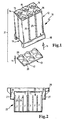
- a module 10 is shown prior to assembly according to the indicated arrows 11.
- This consists of a base body 12 and an additional body 13.
- the main body forms an intake 14, which is formed by the raw-side mouth of cyclone cells 15.
- guide vanes 16 can be seen, which are integrally formed undercuts with the main body 12. Therefore, the part shown can be produced by two mold halves in injection molding technology by these together in the direction of the arrows 11 and are separated again after the injection molding. The same applies to the additional part 13.
- the additional part 13 forms an outlet side 17, which at the same time as a lid for completing a formed by the body, in FIG. 1 unrecognizable collection space 18 is provided.
- an opening 19 is formed, which allows a discharge of the located in the collecting space 18 deposited substrate.
- the substrate passes out of the cyclone cells 15 through an annular gap, which is formed by the in the representation according to FIG. 1 Immerse upwardly facing center tubes 20 in the cyclone cells.
- the interior of the center tubes forms holes in the outlet side 17, which serve to transport the purified fluid.
- the outer sides of the main body 12 and the additional body 13 form a module housing 21st
- FIG. 2 shows a housing 22, which for the purpose of integration of modules according to FIG. 1
- Shooting 23 has.
- ribs 24 are formed in the housing, with corresponding slots 25 (s. FIG. 1 ) of the modules correspond.
- the recordings are further provided with an opening 26 which communicates with the openings 19 of the modules corresponds to the fact that they open into an annular channel 27, which surrounds all modules.
- a flange 28 is provided for receiving a housing cover, not shown.
- the housing in the same representation with already installed modules 10 is in FIG. 4 shown.
- FIGS. 3 and 4 show the housing 22 with built-in modules 10.
- FIG. 3 is a plan view of the housing 22 with the suction 14 to see. It becomes clear that before installation of the modules 10 protective grid 29 are inserted into the recordings. Furthermore, the annular channel 27 can be seen, which surrounds the eight modules used and ends in a dirt discharge 30.
- the grids are designed to prevent coarse particles from being sucked in by the cyclone cells, which would clog the vanes 16 and thus permanently impair the function of the multicellular cyclone.
- the interaction of these components is best FIG. 4 remove.
- the grids 29 rest on the open bottom of the receptacles 23 for the modules 10. Subsequently, the modules are inserted into the recordings. Furthermore, the collecting spaces 18 can be seen, which are formed by the central tubes 20. After inserting the modules 10 into the housing 22, a lid 31 is placed, which separates the annular channel 27 from the outlet side 17 by means of a seal 32.
- the path of the cleaned or the purified fluid is indicated by solid arrows in FIG. 4 indicated. This passes through the suction in the cyclone cells 15 and from there through the center tubes 20 and the outlet side 17 in the interior of the lid 31.
- an enriched with the substances to be separated off-flow is deposited by dashed arrows in FIGS. 3 and 4 is shown.
- this side stream at the outer edge of the central tubes 20 into the collecting space 18 and from there through the openings 19 and apertures 26 in the annular channel 27 passes.
- the annular channel ensures a uniform suction of the deposited substances, starting from the apertures 26 to the protective discharge 30th
- FIG. 5 is an application example of the multicellular cyclone according to FIGS. 3 and 4 can be seen in which this is used as a pre-filter for an air filter.
- the multi-cell cyclone with the housing 22 is flanged to an air filter housing 34, wherein the air filter housing while the function of the lid 31 in accordance with FIG. 4 due.
- the pre-cleaned fluid, in this case air directly to the air filter housing 34 forwarded filter element, passes through this and thus passes to an outlet 35 for the purified air.
- FIG. 6 is a plan view of a multicellular cyclone according to the invention shown in their perspective of the FIG. 3 is similar, but a centrally symmetric configuration of the cyclone cells is shown.
- the housing 22a is shown capped, the configuration of the cyclone cells 15a allows a conclusion to the formation of channel structures 36a, which in particular contain a circular annular channel 27a, which opens into the Schmutzaustrag 30a.
- the cyclone cells 15a of the respective groups are so close together that touch the walls of each adjacent cyclone cells. Therefore, the channel structures 36a are formed as closed structures, whereby a direct discharge of the deposited substances is possible. These are in particular the in FIG. 6 unrecognizable dirt outlets of the individual cyclone cells to the channel structures 36a out aligned.
- the illustrated multicellular cyclone can either be made as a single module with different groups of cyclone cells or the individual groups of cyclone cells are prepared separately as a module.
- a division of the multi-cell cyclone in quarter circles corresponding to the dot-dash line 38 would be conceivable.
- the multicellular cyclone is held in the housing 22a by means of fastening screws 39a.
Landscapes
- Chemical & Material Sciences (AREA)
- Chemical Kinetics & Catalysis (AREA)
- Cyclones (AREA)
- Organic Low-Molecular-Weight Compounds And Preparation Thereof (AREA)
Description
- Die Erfindung betrifft einen Vielzellenzyklon mit einer Vielzahl von parallel geschalteten Zyklonzellen nach der Gattung des Patentanspruchs 1. Außerdem betrifft die Erfindung ein Verfahren zur Herstellung einer Gruppe der genannten Zyklonzellen nach der Gattung des Patentanspruchs 8.
- Derartige Vielzellenzyklone sind beispielsweise aus der
DE 298 19 335 U1 bekannt. Entsprechend dieses Dokumentes kommen die genannten Vielzellenzyklone beispielsweise zur Vorabscheidung von Partikeln in Luftfiltern zum Einsatz.Figur 1 des oben genannten Dokumentes zeigt einen modularen Aufbau des Vielzellenzyklons, wobei die Zyklonzellen 20 zwischen Lochblechen 19 eingebunden sind, wodurch zwischen diesen Lochblechen ein Schmutzsammelraum für die abgeschiedenen Teilchen entsteht, welcher sich durch einen Schmutzaustrag 26 entleeren lässt. Die Zyklonzellen 20 sind Standardbauteile und daher auf Grund der hohen Fertigungszahlen kostengünstig in der Herstellung. Durch die Zusammenfassung der Zyklonzellen lässt sich daher kostengünstig ein Zyklonabscheider realisieren, welcher im Verhältnis zum möglichen Volumendurchsatz ein geringes Bauvolumen beansprucht. Allerdings lassen sich nicht ohne weiteres unbegrenzt viele Zyklonzellen zu einem Vielzellenzyklon zusammenschließen. Je mehr Zyklonzellen vorgesehen sind, desto größer wird das Problem, die abgeschiedenen Substanzen durch den Schmutzaustrag 26 zu entfernen. Dies kann während des Betriebs zu Verstopfungen in einzelnen Zyklonzellen führen, wodurch das Abscheideergebnis des Vielzellenzyklons sowie der durch ihn bewirkte Druckverlust nachteilhaft beeinflusst wird. Die Reinigung großer Arrays von Zyklonzellen muss daher über mehrere Schmutzausträge erfolgen, wodurch ein zusätzlicher konstruktiver Aufwand entsteht und die Wirtschaftlichkeit des derart ausgestatteten Vielzellenzyklons leidet. - Das Dokument
US 4,242,115 offenbart einen Vielzellenzyklon mit einzelnen Zyklonzellen. Die Zyklonzellen sind in mehreren parallelen Reihen angeordnet. Zwischen den Zyklonzellen sind Kanalstrukturen gebildet, durch welche der in den Zyklonzellen abgeschiedene Schmutz zu einem Schmutzaustrag befördert wird. Da die Zyklonzellen zueinander gleichgroße Abstände aufweisen kann es zu Verstopfungen einzelner Zyklonzellen beim Schmutzabtransport kommen, wodurch die Abscheidergebnisse und die Standzeiten beeinträchtigt werden. - Aufgabe der Erfindung ist es daher, einen Vielzellenzyklon zu schaffen, welcher bei vertretbarem Aufwand an Kosten optimale Abscheideergebnisse und Standzeiten erzielt. Diese Aufgabe wird durch die Merkmale der Ansprüche 1 sowie 8 gelöst.
- Der erfindungsgemäße Vielzellenzyklon ist in bekannter Weise aus einzelnen Zyklonzellen aufgebaut, welche eine gemeinschaftliche Ansaugseite für das zu reinigende Fluid und eine Ausblasseite für das gereinigte Fluid aufweisen. Weiterhin ist ein Schmutzaustrag vorgesehen, aus dem die abgeschiedenen Substanzen abgesaugt werden können. Hierzu wird normalerweise ein Unterdruck angelegt, so dass ein Teilstrom des zu reinigenden Fluids zusammen mit den abgeschiedenen Substanzen abgesaugt wird. Zum Zwecke der Absaugung befinden sich die Zyklonzellen in einem Gehäuse, in das der äußere radiale Bereich der Zyklonzellen mündet, in dem sich jeweils die abgeschiedenen Substanzen anreichern. Der reinseitige Ausgang der Zyklonzellen wird durch ein Mittelrohr gebildet, welches in die Zyklonzellen eintaucht und damit den radial inneren Volumenstrom des zu filternden Fluids aufnimmt. Vielzellenzyklone können sowohl zur Abscheidung von Substanzen aus Flüssigkeiten wie auch aus Gasen Verwendung finden. Eine Anwendung finden Vielzellenzyklone als Vorabscheider in Luftfiltern für Verbrennungskraftmaschinen.
- Gekennzeichnet ist die Erfindung dadurch, dass die Zyklonzellen gruppenweise im Gehäuse angeordnet sind. Die einzelnen Gruppen sind derart angeordnet, dass Kanalstrukturen gebildet werden, die den Transport der abgeschiedenen Substanzen hin zum Schmutzaustrag begünstigen. Dabei werden die Kanalstrukturen dadurch gebildet, dass sich im Verhältnis zum Abstand der Zyklonzellen einer Gruppe untereinander eine Volumenaufweitung ergibt, die den Querschnitt zur Durchleitung der abgeschiedenen Substanzen zur Verfügung stellt. Hierdurch kann bei gegebener Absaugleistung eine gleichmäßige Absaugung der gesamten Zyklonzellen erfolgen. Somit werden also auch Zyklonzellen abgesaugt, die eine größere Entfernung zum Schmutzaustrag haben. Einer Verstopfung wird auf diese Weise wirksam entgegengewirkt, wodurch sich bei geringem Bauaufwand eine große Anzahl von Zyklonzellen zu einem Vielzellenzyklon zusammenfassen lässt.
- Die einzelnen Gruppen von Zyklonzellen sind dadurch definiert, dass diese durch die Kanalstrukturen vollständig getrennt sind. Gemäß einer besonderen Ausgestaltung sind die Zyklonzellen innerhalb der Gruppen sogar derart angeordnet, dass jeweils benachbarte Zyklonzellen aneinander stoßen. Dadurch lassen sich geschlossene Kanalstrukturen bilden, wobei die Wände der Zyklonzellen dabei Teile der Wandungen der Kanalstruktur bilden. Die Kanalstrukturen werden weiterhin durch das Gehäuse gebildet, welches den Raum zum Absaugen der abgeschiedenen Substanzen nach außen hin begrenzt.
- Eine andere Ausgestaltung der Erfindung sieht vor, dass die Gruppen von Zyklonzellen in einzelnen Modulen zusammengefasst sind. Diese Module weisen Modulgehäuse auf, welche selbst kleine Sammelräume für die abgeschiedenen Substanzen bilden. Diese Sammelräume sind mit Öffnungen versehen, die in die Kanalstrukturen im Gehäuse münden. Auf diese Weise ist der Vielzellenzyklon gleichsam aus mehreren kleinsten Vielzellenzyklonen in Form der Module gebildet. Die Module haben vorteilhafterweise 4 bis 10 Zellen, da bei dieser Anzahl von Zyklonzellen eine Absaugung mittels eines gemeinschaftlichen Sammelraums noch völlig unproblematisch verläuft. Die Öffnungen der Module münden jedoch in die bereits beschriebenen Kanalstrukturen, so dass alle Module durch den Schmutzaustrag in gleicher Weise abgesaugt werden können. Einem Verstopfen einzelner Module wird daher entsprechend der bereits beschriebenen Weise wirksam entgegengewirkt.
- Eine besondere Ausgestaltung der Erfindung sieht vor, dass die besagten Module selbst Einheiten bilden, die einzeln in das Gehäuse zum Absaugen einsetzbar sind. Auf diese Weise lässt sich ein Baukastensystem verwirklichen, wobei die Module kostengünstig hergestellt werden können und in unterschiedlichen Gehäuse zu Vielzellenzyklonen mit verschiedener Anzahl von Zyklonzellen zusammengesetzt werden können. Daher trägt die Variante mit einzelnen Modulen in besonderer Weise zur Wirtschaftlichkeit des erfindungsgemäßen Vielzellenzyklons bei.
- Gemäß einer vorteilhaften Ausgestaltung sind die Gruppen von Zyklonzellen, welche auch durch die bereits beschriebenen Module gebildet sein können, regelmäßig angeordnet. Hiermit ist insbesondere eine zentral- oder achsensymmetrische Anordnung zueinander gemeint. Durch die symmetrische Anordnung wird bewirkt, dass geordnete Strömungsverhältnisse im Gehäuse hergestellt werden können. Damit wird das Abreinigungsergebnis durch den Schmutzaustrag besser vorhersagbar und die Zuverlässigkeit des Vielzellenzyklons verbessert.
- Eine besonders vorteilhafte Ausgestaltung der Erfindung sieht vor, dass die Kanalstrukturen einen Ringkanal umfassen, der alle Gruppen von Zyklonzellen umringt. Über diesen Ringkanal kann auf einfache Weise das abgeschiedene Substrat über den Schmutzaustrag abgesaugt werden. Insbesondere bei der Verwendung von Modulen ist eine Anordnung möglich, bei der die Öffnungen der Module nach außen in den Ringkanal münden.
- Dadurch entstehen kurze und direkte Absaugwege für die abgeschiedenen Substanzen. In diesem Fall ist also außer dem Ringkanal nicht die Bildung weiterer Kanalstrukturen notwendig. Selbstverständlich kann der Ringkanal aber auch mit Kanalstrukturen verbunden werden, die in das Innere des Vielzellenzyklons hineinreichen und auf diese Weise die einzelnen Zyklonzellen in Gruppen aufteilen.
- Das Abscheideergebnis der erfindungsgemäßen Vielzellenzyklone kann noch verbessert werden, indem einzelne Zyklonzellen durch sogenannte Blindrohre ersetzt werden. Diese schaffen eine direkte Verbindung zwischen Ansaugung und den Kanalstrukturen, so dass die Einleitung von Fluid in das Gehäuse unter einem geringeren Druckverlust möglich wird, als dies durch Verwendung einer entsprechenden Zyklonzelle möglich wäre. Daher können Blindrohre vorteilhafterweise in Bereiche des Vielzellenzyklons eingesetzt werden, die trotz Bildung von Kanalstrukturen problematischer hinsichtlich der Abreinigung sind als der restliche Vielzellenzyklon. Durch Ausbildung als Blindrohr, welches an Stelle einer Zyklonzelle eingesetzt werden kann, kann nach abgeschlossener Konstruktion des Vielzellenzyklons eine Optimierung des Abscheideergebnisses erreicht werden, ohne die Konstruktion wesentlich zu verändern. Daher stellt die Verwendung von Blindrohren eine kostengünstige Alternative dar, beispielsweise Vielzellenzyklone, die als Einzelanfertigung hergestellt werden, mittels Versuchen oder bei bereits erfolgtem Einsatz zu optimieren.
- Ein weiteren Aspekt der Erfindung ist ein Verfahren zur Herstellung von Gruppen von Zyklonen wie es zum Beispiel die
EP 0 256 491 beschreibt. - Ein Verfahren zur Herstellung der erfindungsgemäßen Gruppen von Zyklonzellen sieht vor, dass zumindest ein Teil der Bauelemente, die für die Zyklonzellen notwendig sind, in ein Bauteil integriert werden. Dieses kann insbesondere urformtechnisch z. B. durch Spritzgießen hergestellt werden. Dabei werden alle gleichartigen Bauelemente einer Gruppe in einem Verfahrensschritt hergestellt, so dass die gesamte Gruppe aus Zyklonzellen pro Bauelement nur aus einem Bauteil besteht. Diese Lösung ist besonders wirtschaftlich, da ein großer Teil des Montageaufwandes eingespart werden kann.
- Gemäß einer sinnvollen Ausgestaltung der Erfindung wird eine Gruppe von Zyklonzellen durch einen Grundkörper und einen Zusatzkörper gebildet. Dabei enthält der Grundkörper die röhrenförmige Struktur der Zyklonzellen, die für die Durchleitung des zu reinigenden Fluids vorgesehen ist. Dieser Grundkörper verläuft also von der Ansaugung bis zu der Stelle, wo die abgeschiedenen Substanzen ausgetragen werden sollen. Das Zusatzteil beinhaltet die Auslassseite für das gereinigte Fluid, welches durch Mittelrohre gebildet wird. Diese tauchen in den Grundkörper derart ein, dass in der rohrartigen Struktur ein radial äußerer Bereich entsteht, der für die Trennung des gereinigten Fluids vom abgeschiedenen Substrat verantwortlich ist.
- Gemäß einer weiteren Ausgestaltung der Erfindung können auch die Leitschaufeln in den Grundkörper integriert werden. Diese sind zu diesem Zweck hinterschneidungsfrei bezüglich der Durchströmungsrichtung des Grundkörpers gestaltet. Die Durchströmungsrichtung entspricht nämlich auf Grund der rohrartigen Struktur, die im Grundkörper integriert ist, genau der Entformungsrichtung bei einer gusstechnischen Herstellung des Grundkörpers. Daher sind auch bei Integration der Leitschaufeln nur zwei Formteile zur Herstellung des Grundkörpers notwendig.
- Gemäß einer besonderen Ausgestaltung der Erfindung bildet das nach genanntem Verfahren hergestellte Bauteil ein Modul entsprechend der bereits beschriebenen Struktur. Dies bedeutet, dass der Grundkörper zusammen mit dem Zusatzkörper ein Modulgehäuse bilden muss, welches den Sammelraum für das im Modul abgeschiedene Substrat enthält. Dieses Modulgehäuse lässt sich auf einfache Weise durch Zusammensetzen von Grundkörper und Zusatzkörper bilden, wobei die Öffnung bevorzugt in der Trennfuge zwischen Grundkörper und Zusatzkörper vorgesehen werden kann. Hierdurch entsteht ein kostengünstig zu fertigendes Modul, welches wie bereits erwähnt zur Bildung eines Baukastensystems beitragen kann.
- Diese und weitere Merkmale von bevorzugten Weiterbildungen der Erfindung gehen außer aus den Ansprüchen auch aus der Beschreibung und der Zeichnung hervor, wobei die einzelnen Merkmale jeweils für sich allein oder zu mehreren in Form von Unterkombinationen bei der Ausführungsform der Erfindung und auf anderen Gebieten verwirklicht sein und vorteilhafte sowie für sich schutzfähige Ausführungen darstellen können, für die hier Schutz beansprucht wird.
- Weitere Einzelheiten der Erfindung werden in der Zeichnung anhand von schematischen Ausführungsbeispielen beschrieben. Hierbei zeigen
- Figur 1
- ein Modul für einen bekannten Vielzellenzyklon, bestehend aus Grundkörper und Zusatzkörper in perspektivischer Ansicht,
- Figur 2
- ein Gehäuse, in das bekannte Module gemäß
Figur 1 einsetzbar sind, im Mittelschnitt, - Figur 3
- eine Aufsicht auf das Gehäuse gemäß
Figur 2 im verschlossenen Zustand, - Figur 4
- das Gehäuse in der Darstellung entsprechend
Figur 2 mit eingebauten bekannten Modulen gemäßFigur 1 , - Figur 5
- die Integration eines bekannten Gehäuses gemäß
Figur 3 an einen zylindrischen Luftfilter in perspektivischer Ansicht und - Figur 6
- eine erfindungsgemäße Ausgestaltung eines Vielzellenzyklons in kreisförmiger Gestalt als Aufsicht.
- In
Figur 1 ist ein Modul 10 vor dem Zusammenbau entsprechend der angedeuteten Pfeile 11 dargestellt. Dies besteht aus einem Grundkörper 12 und einem Zusatzkörper 13. Der Grundkörper bildet eine Ansaugung 14, die durch die rohseitige Mündung von Zyklonzellen 15 gebildet ist. In diesen Mündungen sind Leitschaufeln 16 zu erkennen, welche einteilig, hinterschneidungsfrei mit dem Grundkörper 12 ausgebildet sind. Daher lässt sich das gezeigte Teil durch zwei Formhälften in Spritzgusstechnik herstellen, indem diese in Richtung der Pfeile 11 zusammen- und nach dem Spritzgießvorgang wieder auseinandergeführt werden. Selbiges gilt auch für das Zusatzteil 13. - Das Zusatzteil 13 bildet eine Auslassseite 17, welche gleichzeitig als Deckel zum Abschluss eines durch den Grundkörper gebildeten, in
Figur 1 nicht erkennbaren Sammelraums 18 vorgesehen ist. In der dadurch entstehenden Trennfuge ist eine Öffnung 19 gebildet, die einen Austrag des im Sammelraum 18 befindlichen abgeschiedenen Substrats erlaubt. Das Substrat gelangt aus den Zyklonzellen 15 durch einen Ringspalt, der dadurch gebildet wird, dass die in der Darstellung gemäßFigur 1 nach oben zeigenden Mittelrohre 20 in die Zyklonzellen eintauchen. Das Innere der Mittelrohre bildet Löcher in der Auslassseite 17, die einem Transport des gereinigten Fluides dienen. Insgesamt bilden die Außenseiten des Grundkörpers 12 und des Zusatzkörpers 13 ein Modulgehäuse 21. -
Figur 2 zeigt ein Gehäuse 22, welches zum Zwecke der Integration von Modulen gemäßFigur 1 Aufnahmen 23 aufweist. Hierzu sind im Gehäuse Rippen 24 ausgebildet, die mit entsprechenden Schlitzen 25 (s.Figur 1 ) der Module korrespondieren. Die Aufnahmen sind weiterhin mit einem Durchbruch 26 versehen, der mit den Öffnungen 19 der Module dahingehend korrespondiert, dass diese in einen Ringkanal 27 münden, der alle Module umgibt. Zur Aufnahme eines nicht dargestellten Gehäusedeckels ist eine Flanschverbindung 28 vorgesehen. Das Gehäuse in der selben Darstellung mit bereits eingebauten Modulen 10 ist inFigur 4 dargestellt. -
Figur 3 und 4 zeigen das Gehäuse 22 mit eingebauten Modulen 10. InFigur 3 ist eine Aufsicht auf das Gehäuse 22 mit der Ansaugung 14 zu sehen. Es wird deutlich, dass vor dem Einbau der Module 10 Schutzgitter 29 in die Aufnahmen eingelegt werden. Weiterhin lässt sich der Ringkanal 27 erkennen, der die acht verwendeten Module umgibt und in einem Schmutzaustrag 30 endet. - Die Schutzgitter sollen verhindern, dass grobe Teilchen von den Zyklonzellen angesaugt werden, welche die Leitschaufeln 16 zusetzen und so die Funktion des Vielzellenzyklons auf Dauer beeinträchtigen würden. Das Zusammenwirken dieser Bauteile lässt sich am besten
Figur 4 entnehmen. Die Gitter 29 liegen auf dem offenen Boden der Aufnahmen 23 für die Module 10 auf. Anschließend werden die Module in die Aufnahmen eingesetzt. Weiterhin sind die Sammelräume 18 zu erkennen, welche durch die Mittelrohre 20 gebildet werden. Nach dem Einsetzen der Module 10 in das Gehäuse 22 wird ein Deckel 31 aufgesetzt, der den Ringkanal 27 von der Auslassseite 17 mittels einer Dichtung 32 trennt. - Der Weg des zu reinigenden bzw. des gereinigten Fluids ist durch durchgezogene Pfeile in
Figur 4 angedeutet. Dieses gelangt durch die Ansaugung in die Zyklonzellen 15 und von dort durch die Mittelrohre 20 und die Auslassseite 17 in das Innere des Deckels 31. Durch den Drall in den Zyklonrohren wird ein mit den abzuscheidenden Substanzen angereicherter Nebenstrom abgeschieden, der durch gestrichelte Pfeile inFigur 3 und 4 dargestellt ist. DerFigur 4 ist zu entnehmen, dass dieser Nebenstrom am äußeren Rand der Mittelrohre 20 in den Sammelraum 18 und von dort durch die Öffnungen 19 und Durchbrüche 26 in den Ringkanal 27 gelangt. WieFigur 3 zu entnehmen ist, sorgt der Ringkanal für eine gleichmäßige Absaugung der abgeschiedenen Substanzen ausgehend von den Durchbrüchen 26 hin zum Schutzaustrag 30. - Der
Figur 5 ist ein Anwendungsbeispiel des Vielzellenzyklons gemäßFigur 3 und 4 zu entnehmen, bei dem dieser als Vorfilter für einen Luftfilter zum Einsatz kommt. Zu diesem Zweck ist der Vielzellenzyklon mit dem Gehäuse 22 an ein Luftfiltergehäuse 34 angeflanscht, wobei dem Luftfiltergehäuse dabei die Funktion des Deckels 31 gemäßFigur 4 zukommt. Dadurch wird das vorgereinigte Fluid, in diesem Fall Luft, direkt an das im Luftfiltergehäuse 34 eingebaute Filterelement weitergeleitet, durchtritt dieses und gelangt so zu einem Auslass 35 für die gereinigte Luft. - In
Figur 6 ist eine Aufsicht auf einen erfindungsgemäßen Vielzellenzyklon dargestellt, die in ihrer Perspektive derFigur 3 ähnelt, allerdings ist eine zentralsymmetrische Konfiguration der Zyklonzellen dargestellt. Das Gehäuse 22a ist zwar gedeckelt dargestellt, allerdings lässt die Konfiguration der Zyklonzellen 15a einen Rückschluss auf die Ausbildung von Kanalstrukturen 36a zu, die insbesondere einen kreisförmig ausgebildeten Ringkanal 27a enthalten, der in den Schmutzaustrag 30a mündet. Die Zyklonzellen 15a der jeweiligen Gruppen stehen so dicht beieinander, dass sich die Wände der jeweils benachbarten Zyklonzellen berühren. Daher sind die Kanalstrukturen 36a als geschlossene Strukturen ausgebildet, wodurch eine direkte Ausleitung der abgeschiedenen Substanzen möglich wird. Hierzu sind insbesondere die inFigur 6 nicht zu erkennenden Schmutzauslässe der einzelnen Zyklonzellen zu den Kanalstrukturen 36a hin ausgerichtet. - Im oberen Bereich des Vielzellenzyklons, der am weitesten vom Schmutzaustrag 30a entfernt ist, kommen zwei Blindrohre 37a zum Einsatz, die jeweils eine Zyklonzelle ersetzen. Hierdurch wird in diesem Bereich zusätzliche Luft in die Kanalstrukturen 36a eingeleitet, die den Abtransport der abgeschiedenen Substanzen unterstützen. Gleichzeitig sind die beiden Zyklonzellen, welche am stärksten verstopfungsgefährdet werden, durch die Blindrohre ausgetauscht. Hier hätte nämlich entgegen der Schwerkraft ein Abtransport der Substanzen erfolgen müssen, da der Vielzellenzyklon in der dargestellten Weise mit Schmutzaustrag 30a nach unten eingebaut wird.
- Der dargestellte Vielzellenzyklon kann entweder als ein einziges Modul mit verschiedenen Gruppen von Zyklonzellen hergestellt werden oder die einzelnen Gruppen von Zyklonzellen werden gesondert als Modul hergestellt. Hier wäre beispielsweise eine Teilung des Vielzellenzyklons in Viertelkreise entsprechend der strichpunktierten Linie 38 denkbar. Der Vielzellenzyklon wird mittels Befestigungsschrauben 39a im Gehäuse 22a gehalten.
Claims (9)
- Vielzellenzyklon, enthaltend eine Vielzahl von Zyklonzellen (15, 15a), eine Ansaugseite (14) für das zu reinigende Fluid und eine Ausblasseite (17) für das gereinigte Fluid sowie ein Gehäuse (22, 22a) mit einem Schmutzaustrag (30, 30a) für die aus dem Fluid abgeschiedenen Substanzen, dadurch gekennzeichnet, dass die Zyklonzellen (15, 15a) in der Art gruppenweise im Gehäuse angeordnet sind, dass die einzelnen Gruppen mittels Kanalstrukturen (36a) mit dem Schmutzaustrag verbunden sind, wobei die Zyklonzellen einer Gruppe unterschiedliche Abstände zueinander aufweisen und wobei die Kanalstrukturen im Verhältnis zum Abstand der Zyklonzellen einer Gruppe untereinander einen aufgeweiteten Querschnitt zur Durchleitung der abgeschiedenen Substanzen aufweisen.
- Vielzellenzyklon nach Anspruch 1, dadurch gekennzeichnet, dass die Gruppen von Zyklonzellen (15, 15a) derart angeordnet sind, dass sich jeweils benachbarte Zyklonzellen berühren, wodurch geschlossene Kanalstrukturen gebildet sind.
- Vielzellenzyklon nach Anspruch 1, dadurch gekennzeichnet, dass die Gruppen von Zyklonzellen (15, 15a) in einzelnen Modulen (10) zusammengefasst sind, wobei die Module je ein Modulgehäuse (21) aufweisen, welches Sammelräume (18) für die abgeschiedenen Substanzen bildet und wobei die Sammelräume je mindestens eine Öffnung (19) zu den Kanalstrukturen (36a) des Gehäuses (22, 22a) aufweisen.
- Vielzellenzyklon nach Anspruch 3, dadurch gekennzeichnet, dass die Module (10) einzeln in das Gehäuse (22, 22a) einsetzbar sind.
- Vielzellenzyklon nach einem der vorherigen Ansprüche, dadurch gekennzeichnet, dass die Gruppen von Zyklonzellen zentral- oder achsensymmetrisch zueinander angeordnet sind.
- Vielzellenzyklon nach einem der vorherigen Ansprüche, dadurch gekennzeichnet, dass die Kanalstrukturen (36a) einen Ringkanal (27, 27a) umfassen, der alle Gruppen von Zyklonzellen (15, 15a) umringt und mit dem Schmutzaustrag (30, 30a) in Verbindung steht.
- Vielzellenzyklon nach einem der vorherigen Ansprüche, dadurch gekennzeichnet, dass mindestens eine Zyklonzelle einer Gruppe durch ein Blindrohr (37a) ersetzt ist, welches eine Verbindung zwischen der Ansaugung (14) und den Kanalstrukturen (36a) schafft, derart, dass der Strömungswiderstand im Blindrohr (37a) geringer ist, als derjenige der ersetzten Zyklonzelle.
- Verfahren zur Herstellung einer Gruppe von Zyklonzellen (15, 15a) für einen Vielzellenzyklon, wobei zumindest ein Teil der Bauelemente der Zyklonzellen jeweils in einem Bauteil in Urformtechnik, insbesondere durch Spritzgießen, hergestellt werden, derart, dass dieses Bauteil alle gleichartigen Bauelemente der Gruppe beinhaltet, wobei eines der besagten Bauteile einen die Ansaugung (14) enthaltenden Grundkörper (12) bildet, der die Durchleitung des zu reinigenden Fluides gewährleistet und ein zweites der besagten Bauteile einen die Auslassseite (17) und Mittelrohre (20) zur Trennung des gereinigten Fluides vom abgeschiedenen Substrat enthaltenden Zusatzkörper (13), wobei die Leitschaufeln (16) der Zyklonzellen (15, 15a) hinterschneidungsfrei bezüglich der Durchströmungsrichtung des Grundkörpers (12) in selbigen integriert sind.
- Verfahren nach Anspruch 8, dadurch gekennzeichnet, dass durch das Zusammensetzen von Grundkörper (12) und Zusatzkörper (13) ein Modul (10) entsprechend der Ausgestaltung nach Anspruch 3 gebildet wird, mit einem Modulgehäuse (21), welches eine Öffnung (19) zum Austrag des abgeschiedenen Substrates aufweist.
Applications Claiming Priority (2)
| Application Number | Priority Date | Filing Date | Title |
|---|---|---|---|
| DE10142701A DE10142701A1 (de) | 2001-08-31 | 2001-08-31 | Vielzellenzyklon und Verfahren zu dessen Herstellung |
| DE10142701 | 2001-08-31 |
Publications (2)
| Publication Number | Publication Date |
|---|---|
| EP1287896A1 EP1287896A1 (de) | 2003-03-05 |
| EP1287896B1 true EP1287896B1 (de) | 2008-05-21 |
Family
ID=7697262
Family Applications (1)
| Application Number | Title | Priority Date | Filing Date |
|---|---|---|---|
| EP02017269A Expired - Lifetime EP1287896B1 (de) | 2001-08-31 | 2002-08-01 | Vielzellenzyklon und Verfahren zu dessen Herstellung |
Country Status (5)
| Country | Link |
|---|---|
| US (1) | US6884273B2 (de) |
| EP (1) | EP1287896B1 (de) |
| JP (1) | JP4342778B2 (de) |
| AT (1) | ATE395981T1 (de) |
| DE (2) | DE10142701A1 (de) |
Cited By (5)
| Publication number | Priority date | Publication date | Assignee | Title |
|---|---|---|---|---|
| US9885196B2 (en) | 2015-01-26 | 2018-02-06 | Hayward Industries, Inc. | Pool cleaner power coupling |
| US9885194B1 (en) | 2017-05-11 | 2018-02-06 | Hayward Industries, Inc. | Pool cleaner impeller subassembly |
| US9896858B1 (en) | 2017-05-11 | 2018-02-20 | Hayward Industries, Inc. | Hydrocyclonic pool cleaner |
| US9909333B2 (en) | 2015-01-26 | 2018-03-06 | Hayward Industries, Inc. | Swimming pool cleaner with hydrocyclonic particle separator and/or six-roller drive system |
| US10156083B2 (en) | 2017-05-11 | 2018-12-18 | Hayward Industries, Inc. | Pool cleaner power coupling |
Families Citing this family (47)
| Publication number | Priority date | Publication date | Assignee | Title |
|---|---|---|---|---|
| US6932849B2 (en) * | 2003-07-24 | 2005-08-23 | Deere & Company | Serviceable vortex-type filter assembly and method for servicing same |
| FR2870754B1 (fr) * | 2004-05-28 | 2006-07-21 | Renault Sas | Dispositif de filtre de vehicule |
| FR2870755A1 (fr) * | 2004-05-28 | 2005-12-02 | Renault Sas | Dispositif de filtre de vehicule |
| KR101148125B1 (ko) * | 2005-01-07 | 2012-05-23 | 삼성전자주식회사 | 사이클론 청소기 |
| GB0504312D0 (en) * | 2005-03-02 | 2005-04-06 | Boc Group Plc | Trap device |
| KR100622550B1 (ko) * | 2005-03-29 | 2006-09-13 | 삼성광주전자 주식회사 | 진공청소기용 사이클론 집진장치 및 그 사이클론집진장치를 구비하는 진공청소기 |
| KR100607442B1 (ko) * | 2005-03-29 | 2006-08-02 | 삼성광주전자 주식회사 | 멀티 사이클론 집진 장치 및 이를 이용한 진공 청소기 |
| DE102005031059A1 (de) | 2005-07-02 | 2007-01-04 | Mahle International Gmbh | Als Vorfilter dienender Gaseintrittsbereich eines Gasfiltergehäuses |
| KR101003417B1 (ko) * | 2005-08-17 | 2010-12-23 | 엘지전자 주식회사 | 진공 청소기의 집진장치 |
| US7776120B2 (en) * | 2006-03-10 | 2010-08-17 | G.B.D. Corp. | Vacuum cleaner with a moveable divider plate |
| NO326078B1 (no) * | 2006-07-07 | 2008-09-15 | Shell Int Research | Fluidseparasjonskar |
| DE202006015231U1 (de) * | 2006-10-02 | 2008-02-14 | Mann + Hummel Gmbh | Vorrichtung zum Abscheiden von Partikeln aus einem Gasstrom |
| GB2445027B (en) * | 2006-12-22 | 2011-08-10 | Hoover Ltd | Cyclonic separation apparatus |
| US7879123B2 (en) * | 2007-09-27 | 2011-02-01 | Pall Corporation | Inertial separator |
| BRPI0907152B1 (pt) * | 2008-02-26 | 2020-03-24 | Mann+Hummel Gmbh | Filtro de ar para um motor de combustão interna |
| DE202008015957U1 (de) * | 2008-12-03 | 2010-04-29 | Dolmar Gmbh | Ansaugsystem zum Ansaugen einer Verbrennungsluft und handgeführtes Arbeitsgerät |
| DE202009001693U1 (de) * | 2009-02-11 | 2010-08-19 | Mann+Hummel Gmbh | Luftfilter eines Verbrennungsmotors |
| US7931718B2 (en) * | 2009-04-09 | 2011-04-26 | San Ford Machinery Co., Ltd. | Oil mist separator |
| US8262761B2 (en) | 2009-04-21 | 2012-09-11 | Mann + Hummel Gmbh | Modular cyclone precleaner system and method |
| EP2335799A1 (de) * | 2009-12-04 | 2011-06-22 | Nifco UK Limited | Trennsystem zum Trennen von festen oder flüssigen, in einem Gas verteilten Partikeln |
| DE102010032169B4 (de) * | 2010-07-23 | 2016-11-17 | Mann + Hummel Gmbh | Zyklonabscheider zum Abscheiden von Partikeln aus einem Gasstrom |
| KR101440027B1 (ko) * | 2012-06-29 | 2014-09-17 | 한국철도기술연구원 | 축부재 내의 누적된 미세입자에 대한 블로잉-석션 방식의 제거 기능을 가지는 모듈형 싸이클론 방식의 공기정화장치 |
| US20130152878A1 (en) * | 2013-02-17 | 2013-06-20 | GroupAg LLC | Regenerative Vapor/Particle Generator |
| EP2898955A1 (de) * | 2014-01-24 | 2015-07-29 | Nederlandse Organisatie voor toegepast- natuurwetenschappelijk onderzoek TNO | Multizyklon-Staubtrennvorrichtung |
| JP6286666B2 (ja) * | 2014-03-17 | 2018-03-07 | パナソニックIpマネジメント株式会社 | 集塵装置 |
| KR101593302B1 (ko) | 2014-05-02 | 2016-02-15 | 유-페이 호 | 기류로부터 고형 불순물을 분리하기 위한 모듈형 사이클론 분리장치 |
| JP5837136B2 (ja) * | 2014-05-14 | 2015-12-24 | 玉 佩 何 | サイクロン式セパレータモジュール |
| DE102015006497B4 (de) * | 2014-06-02 | 2022-11-10 | Mann+Hummel Gmbh | Zyklonabscheider sowie Filtervorrichtung mit Zyklonabscheider |
| CN114711662B (zh) * | 2015-07-24 | 2024-07-09 | 恩弗里德系统公司 | 用于从空气和流体中分离颗粒的装置、方法和系统 |
| DE102015221492A1 (de) * | 2015-11-03 | 2017-05-04 | Mahle International Gmbh | Filtereinrichtung, insbesondere Zyklonabscheider |
| CN105289114B (zh) * | 2015-12-08 | 2017-07-04 | 江苏揽山环境科技股份有限公司 | 除雾除尘叶片组 |
| CN105289117B (zh) * | 2015-12-08 | 2017-11-10 | 江苏揽山环境科技股份有限公司 | 除雾器 |
| US11135537B2 (en) * | 2017-01-23 | 2021-10-05 | Enverid Systems, Inc. | Long life air filter |
| EP3589833B1 (de) | 2017-03-03 | 2023-04-26 | Donaldson Company, Inc. | Vorrichtung zur vorreinigung einer motorluftansaugung und methoden |
| US10746141B2 (en) | 2017-03-14 | 2020-08-18 | Kohler Co. | Engine air cleaner |
| WO2019018788A1 (en) | 2017-07-20 | 2019-01-24 | Enverid Systems, Inc. | CONTROL OF FLOW AND PRESSURE IN CYCLONE FILTER NETWORKS |
| PL3675983T3 (pl) * | 2017-08-31 | 2023-09-04 | Donaldson Company, Inc. | Wkłady filtrów; zespoły filtra powietrza |
| KR102023396B1 (ko) * | 2017-09-22 | 2019-09-20 | 엘지전자 주식회사 | 집진장치 및 이를 구비하는 청소기 |
| KR102023395B1 (ko) | 2017-09-22 | 2019-09-20 | 엘지전자 주식회사 | 집진장치 및 이를 구비하는 청소기 |
| KR102047332B1 (ko) | 2017-09-22 | 2019-11-21 | 엘지전자 주식회사 | 집진장치 및 이를 구비하는 청소기 |
| KR102021860B1 (ko) * | 2017-09-28 | 2019-09-17 | 엘지전자 주식회사 | 집진장치 및 이를 구비하는 청소기 |
| US20210291202A1 (en) * | 2018-08-31 | 2021-09-23 | Enverid Systems, Inc. | Systems, devices, and methods for cyclonic filteration |
| CN109692527B (zh) * | 2019-01-31 | 2023-10-03 | 中国航天系统科学与工程研究院 | 旋风除尘管及除尘过滤设备 |
| WO2021148945A1 (en) * | 2020-01-21 | 2021-07-29 | Bibby Darren Richard | Cyclonic air filtration equipment |
| US12311300B2 (en) * | 2022-08-03 | 2025-05-27 | Hamilton Sundstrand Corporation | Mid-pressure water separation for environmental control system |
| US12521660B2 (en) * | 2023-04-26 | 2026-01-13 | Caterpillar Inc. | Integrated manifold for pre-cleaner dust removal |
| US20240390920A1 (en) * | 2023-05-25 | 2024-11-28 | Mann+Hummel Gmbh | Radially oriented, modular pre-cleaner system |
Family Cites Families (17)
| Publication number | Priority date | Publication date | Assignee | Title |
|---|---|---|---|---|
| US2472995A (en) * | 1946-07-13 | 1949-06-14 | Aerotec Corp | Apparatus for separating suspended particles from gases |
| BE490963A (de) * | 1948-09-04 | |||
| NL81887C (de) * | 1954-05-15 | |||
| AT198736B (de) * | 1954-12-09 | 1958-07-25 | Tongeren N V Bureau Van | Mehrfachfliehkraftabscheider |
| US3520114A (en) * | 1968-06-28 | 1970-07-14 | Pall Corp | Vortex air cleaner assembly having uniform particle removal efficiency throughout the array of air cleaners |
| DE2026169A1 (en) * | 1970-05-29 | 1971-12-09 | Licentia Gmbh | Steam separator with cyclones - esp for water reactors - suitable for part load operation |
| US3707830A (en) * | 1971-05-18 | 1973-01-02 | Bahco Ventilation Ab | Cyclone separator |
| US3915679A (en) * | 1973-04-16 | 1975-10-28 | Pall Corp | Vortex air cleaner array |
| US4242115A (en) * | 1979-02-05 | 1980-12-30 | Donaldson Company, Inc. | Air cleaner assembly |
| DE3103842A1 (de) * | 1981-02-05 | 1982-09-09 | Anton Piller GmbH & Co KG, 3360 Osterode | Wirbelkammerfilter zum ausscheiden von feststoffen aus einem gasstrom |
| FI65920C (fi) * | 1983-01-21 | 1984-08-10 | Nobar Ky | Foerfarande och anordning foer separering av ett medium i olika komponenter |
| US4537608A (en) * | 1983-11-16 | 1985-08-27 | Pall Corporation | System for removing contaminant particles from a gas |
| DE3627539A1 (de) * | 1986-08-13 | 1988-02-18 | Piller Gmbh Co Kg Anton | Fliehkraftstaubabscheider mit einer mehrzahl von zyklonen |
| US4746340A (en) * | 1986-10-28 | 1988-05-24 | Donaldson Company, Inc. | Air cleaner apparatus |
| US4767425A (en) * | 1987-07-06 | 1988-08-30 | The United States Of America As Represented By The Secretary Of The Army | Aspirator mechanism for turbine engine air cleaner |
| DE29819335U1 (de) | 1998-10-30 | 1999-04-15 | Filterwerk Mann & Hummel Gmbh, 71638 Ludwigsburg | Filter für gasförmige Medien mit Zyklon zur Vorabscheidung |
| DE19951312A1 (de) * | 1999-10-25 | 2001-05-03 | Reinz Dichtungs Gmbh | Nebelabscheidevorrichtung und Abscheide-Element für eine Nebelabscheidevorrichtung |
-
2001
- 2001-08-31 DE DE10142701A patent/DE10142701A1/de not_active Withdrawn
-
2002
- 2002-08-01 DE DE50212286T patent/DE50212286D1/de not_active Expired - Lifetime
- 2002-08-01 AT AT02017269T patent/ATE395981T1/de not_active IP Right Cessation
- 2002-08-01 EP EP02017269A patent/EP1287896B1/de not_active Expired - Lifetime
- 2002-08-28 JP JP2002249528A patent/JP4342778B2/ja not_active Expired - Lifetime
- 2002-08-28 US US10/229,272 patent/US6884273B2/en not_active Expired - Lifetime
Cited By (10)
| Publication number | Priority date | Publication date | Assignee | Title |
|---|---|---|---|---|
| US9885196B2 (en) | 2015-01-26 | 2018-02-06 | Hayward Industries, Inc. | Pool cleaner power coupling |
| US9909333B2 (en) | 2015-01-26 | 2018-03-06 | Hayward Industries, Inc. | Swimming pool cleaner with hydrocyclonic particle separator and/or six-roller drive system |
| US10557278B2 (en) | 2015-01-26 | 2020-02-11 | Hayward Industries, Inc. | Pool cleaner with cyclonic flow |
| US11236523B2 (en) | 2015-01-26 | 2022-02-01 | Hayward Industries, Inc. | Pool cleaner with cyclonic flow |
| US12065854B2 (en) | 2015-01-26 | 2024-08-20 | Hayward Industries, Inc. | Pool cleaner with cyclonic flow |
| US9885194B1 (en) | 2017-05-11 | 2018-02-06 | Hayward Industries, Inc. | Pool cleaner impeller subassembly |
| US9896858B1 (en) | 2017-05-11 | 2018-02-20 | Hayward Industries, Inc. | Hydrocyclonic pool cleaner |
| US10156083B2 (en) | 2017-05-11 | 2018-12-18 | Hayward Industries, Inc. | Pool cleaner power coupling |
| US10253517B2 (en) | 2017-05-11 | 2019-04-09 | Hayward Industries, Inc. | Hydrocyclonic pool cleaner |
| US10767382B2 (en) | 2017-05-11 | 2020-09-08 | Hayward Industries, Inc. | Pool cleaner impeller subassembly |
Also Published As
| Publication number | Publication date |
|---|---|
| DE50212286D1 (de) | 2008-07-03 |
| EP1287896A1 (de) | 2003-03-05 |
| ATE395981T1 (de) | 2008-06-15 |
| US20030057151A1 (en) | 2003-03-27 |
| US6884273B2 (en) | 2005-04-26 |
| JP2003144978A (ja) | 2003-05-20 |
| JP4342778B2 (ja) | 2009-10-14 |
| DE10142701A1 (de) | 2003-04-03 |
Similar Documents
| Publication | Publication Date | Title |
|---|---|---|
| EP1287896A1 (de) | Vielzellenzyklon und Verfahren zu dessen Herstellung | |
| EP1899036B1 (de) | Als vorfilter dienender gaseintrittsbereich eines gasfiltergehäuses | |
| DE102012011358B4 (de) | Fliehkraftabscheider und Verfahren zum Herstellen eines Fliehkraftabscheiders | |
| DE602004006277T2 (de) | Filteranordnung mit entlüftetem filterelement | |
| DE102016119504B4 (de) | Filterelement, Filteranordnung und Verfahren zum Herstellen eines Filterelements mit Entlüftungsleitung | |
| EP2478207B1 (de) | Kraftstofffilter einer brennkraftmaschine | |
| EP2052136B1 (de) | Vorrichtung zur abscheidung von flüssigkeiten aus gasen | |
| EP1262223B1 (de) | Trägheitsabscheider | |
| DE69705240T2 (de) | Eingekapseltes linsenförmiges patronenfilter | |
| EP1740287A1 (de) | Kraftstofffilter | |
| EP1890789B1 (de) | Filteranordnung für dunstabzugshaube | |
| WO2011124675A1 (de) | Zyklonabscheider | |
| WO2011107262A1 (de) | Filter sowie hierfür vorgesehenes filterelement | |
| EP1500423A1 (de) | Filterzusammenbau des Wirbeltyps | |
| DE102007014573A1 (de) | Filteranlage | |
| DE202008006719U1 (de) | Abscheider für eine Kurbelgehäuseentlüftung einer Brennkraftmaschine | |
| WO2018185272A1 (de) | Filtereinrichtung | |
| DE2623133A1 (de) | Filter zum trennen hoeherer dichte von material geringerer dichte | |
| DE102018105588B4 (de) | Zentrifugalabscheider zum Abscheiden von Öltröpfchen aus dem Kurbelgehäuseentlüftungsgas einer Brennkraftmaschine | |
| EP1556202B1 (de) | Rückspülbare filtervorrichtung für geschmolzenes material und verteiler für eine solche filtervorrichtung | |
| DE102017108168A1 (de) | Rotor eines Zentrifugalabscheiders zum Abscheiden von Flüssigkeits- und/oder Feststoffpartikeln aus einem Gasstrom | |
| AT399313B (de) | Filtriervorrichtung für thermoplastisches kunststoffmaterial | |
| DE102016214516A1 (de) | Filteranlage | |
| EP0436079B1 (de) | Ölabscheider für Gase aus einem Kurbelgehäuse einer Brennkraftmaschine | |
| WO2013083309A1 (de) | Kraftstofffilter und kraftstofffilteranordnung zum filtern von kraftstoff |
Legal Events
| Date | Code | Title | Description |
|---|---|---|---|
| PUAI | Public reference made under article 153(3) epc to a published international application that has entered the european phase |
Free format text: ORIGINAL CODE: 0009012 |
|
| AK | Designated contracting states |
Kind code of ref document: A1 Designated state(s): AT BE BG CH CY CZ DE DK EE ES FI FR GB GR IE IT LI LU MC NL PT SE SK TR Designated state(s): AT BE BG CH CY CZ DE DK EE ES FI FR GB GR IE IT LI LU MC NL PT SE SK TR |
|
| AX | Request for extension of the european patent |
Extension state: AL LT LV MK RO SI |
|
| 17P | Request for examination filed |
Effective date: 20030702 |
|
| AKX | Designation fees paid |
Designated state(s): AT BE BG CH CY CZ DE DK EE ES FI FR GB GR IE IT LI LU MC NL PT SE SK TR |
|
| RAP1 | Party data changed (applicant data changed or rights of an application transferred) |
Owner name: MANN + HUMMEL GMBH |
|
| 17Q | First examination report despatched |
Effective date: 20061010 |
|
| 17Q | First examination report despatched |
Effective date: 20061010 |
|
| GRAP | Despatch of communication of intention to grant a patent |
Free format text: ORIGINAL CODE: EPIDOSNIGR1 |
|
| GRAS | Grant fee paid |
Free format text: ORIGINAL CODE: EPIDOSNIGR3 |
|
| GRAA | (expected) grant |
Free format text: ORIGINAL CODE: 0009210 |
|
| AK | Designated contracting states |
Kind code of ref document: B1 Designated state(s): AT BE BG CH CY CZ DE DK EE ES FI FR GB GR IE IT LI LU MC NL PT SE SK TR |
|
| REG | Reference to a national code |
Ref country code: GB Ref legal event code: FG4D Free format text: NOT ENGLISH |
|
| REG | Reference to a national code |
Ref country code: CH Ref legal event code: EP |
|
| REF | Corresponds to: |
Ref document number: 50212286 Country of ref document: DE Date of ref document: 20080703 Kind code of ref document: P |
|
| REG | Reference to a national code |
Ref country code: IE Ref legal event code: FG4D Free format text: LANGUAGE OF EP DOCUMENT: GERMAN |
|
| PG25 | Lapsed in a contracting state [announced via postgrant information from national office to epo] |
Ref country code: FI Free format text: LAPSE BECAUSE OF FAILURE TO SUBMIT A TRANSLATION OF THE DESCRIPTION OR TO PAY THE FEE WITHIN THE PRESCRIBED TIME-LIMIT Effective date: 20080521 Ref country code: ES Free format text: LAPSE BECAUSE OF FAILURE TO SUBMIT A TRANSLATION OF THE DESCRIPTION OR TO PAY THE FEE WITHIN THE PRESCRIBED TIME-LIMIT Effective date: 20080901 |
|
| NLV1 | Nl: lapsed or annulled due to failure to fulfill the requirements of art. 29p and 29m of the patents act | ||
| PG25 | Lapsed in a contracting state [announced via postgrant information from national office to epo] |
Ref country code: NL Free format text: LAPSE BECAUSE OF FAILURE TO SUBMIT A TRANSLATION OF THE DESCRIPTION OR TO PAY THE FEE WITHIN THE PRESCRIBED TIME-LIMIT Effective date: 20080521 |
|
| REG | Reference to a national code |
Ref country code: IE Ref legal event code: FD4D |
|
| PG25 | Lapsed in a contracting state [announced via postgrant information from national office to epo] |
Ref country code: SE Free format text: LAPSE BECAUSE OF FAILURE TO SUBMIT A TRANSLATION OF THE DESCRIPTION OR TO PAY THE FEE WITHIN THE PRESCRIBED TIME-LIMIT Effective date: 20080821 Ref country code: PT Free format text: LAPSE BECAUSE OF FAILURE TO SUBMIT A TRANSLATION OF THE DESCRIPTION OR TO PAY THE FEE WITHIN THE PRESCRIBED TIME-LIMIT Effective date: 20081021 Ref country code: IE Free format text: LAPSE BECAUSE OF FAILURE TO SUBMIT A TRANSLATION OF THE DESCRIPTION OR TO PAY THE FEE WITHIN THE PRESCRIBED TIME-LIMIT Effective date: 20080521 Ref country code: CZ Free format text: LAPSE BECAUSE OF FAILURE TO SUBMIT A TRANSLATION OF THE DESCRIPTION OR TO PAY THE FEE WITHIN THE PRESCRIBED TIME-LIMIT Effective date: 20080521 Ref country code: DK Free format text: LAPSE BECAUSE OF FAILURE TO SUBMIT A TRANSLATION OF THE DESCRIPTION OR TO PAY THE FEE WITHIN THE PRESCRIBED TIME-LIMIT Effective date: 20080521 |
|
| PG25 | Lapsed in a contracting state [announced via postgrant information from national office to epo] |
Ref country code: SK Free format text: LAPSE BECAUSE OF FAILURE TO SUBMIT A TRANSLATION OF THE DESCRIPTION OR TO PAY THE FEE WITHIN THE PRESCRIBED TIME-LIMIT Effective date: 20080521 |
|
| PLBE | No opposition filed within time limit |
Free format text: ORIGINAL CODE: 0009261 |
|
| STAA | Information on the status of an ep patent application or granted ep patent |
Free format text: STATUS: NO OPPOSITION FILED WITHIN TIME LIMIT |
|
| PG25 | Lapsed in a contracting state [announced via postgrant information from national office to epo] |
Ref country code: MC Free format text: LAPSE BECAUSE OF NON-PAYMENT OF DUE FEES Effective date: 20080831 |
|
| REG | Reference to a national code |
Ref country code: CH Ref legal event code: PL |
|
| 26N | No opposition filed |
Effective date: 20090224 |
|
| PG25 | Lapsed in a contracting state [announced via postgrant information from national office to epo] |
Ref country code: EE Free format text: LAPSE BECAUSE OF FAILURE TO SUBMIT A TRANSLATION OF THE DESCRIPTION OR TO PAY THE FEE WITHIN THE PRESCRIBED TIME-LIMIT Effective date: 20080521 Ref country code: BG Free format text: LAPSE BECAUSE OF FAILURE TO SUBMIT A TRANSLATION OF THE DESCRIPTION OR TO PAY THE FEE WITHIN THE PRESCRIBED TIME-LIMIT Effective date: 20080821 |
|
| PG25 | Lapsed in a contracting state [announced via postgrant information from national office to epo] |
Ref country code: CH Free format text: LAPSE BECAUSE OF NON-PAYMENT OF DUE FEES Effective date: 20080831 Ref country code: LI Free format text: LAPSE BECAUSE OF NON-PAYMENT OF DUE FEES Effective date: 20080831 |
|
| PG25 | Lapsed in a contracting state [announced via postgrant information from national office to epo] |
Ref country code: BE Free format text: LAPSE BECAUSE OF NON-PAYMENT OF DUE FEES Effective date: 20080831 |
|
| PG25 | Lapsed in a contracting state [announced via postgrant information from national office to epo] |
Ref country code: AT Free format text: LAPSE BECAUSE OF NON-PAYMENT OF DUE FEES Effective date: 20080801 |
|
| PG25 | Lapsed in a contracting state [announced via postgrant information from national office to epo] |
Ref country code: LU Free format text: LAPSE BECAUSE OF NON-PAYMENT OF DUE FEES Effective date: 20080801 Ref country code: CY Free format text: LAPSE BECAUSE OF FAILURE TO SUBMIT A TRANSLATION OF THE DESCRIPTION OR TO PAY THE FEE WITHIN THE PRESCRIBED TIME-LIMIT Effective date: 20080521 |
|
| PG25 | Lapsed in a contracting state [announced via postgrant information from national office to epo] |
Ref country code: TR Free format text: LAPSE BECAUSE OF FAILURE TO SUBMIT A TRANSLATION OF THE DESCRIPTION OR TO PAY THE FEE WITHIN THE PRESCRIBED TIME-LIMIT Effective date: 20080521 |
|
| PG25 | Lapsed in a contracting state [announced via postgrant information from national office to epo] |
Ref country code: GR Free format text: LAPSE BECAUSE OF FAILURE TO SUBMIT A TRANSLATION OF THE DESCRIPTION OR TO PAY THE FEE WITHIN THE PRESCRIBED TIME-LIMIT Effective date: 20080822 |
|
| REG | Reference to a national code |
Ref country code: FR Ref legal event code: PLFP Year of fee payment: 15 |
|
| REG | Reference to a national code |
Ref country code: FR Ref legal event code: PLFP Year of fee payment: 16 |
|
| REG | Reference to a national code |
Ref country code: DE Ref legal event code: R081 Ref document number: 50212286 Country of ref document: DE Owner name: MANN+HUMMEL GMBH, DE Free format text: FORMER OWNER: MANN + HUMMEL GMBH, 71638 LUDWIGSBURG, DE |
|
| REG | Reference to a national code |
Ref country code: FR Ref legal event code: PLFP Year of fee payment: 17 |
|
| PGFP | Annual fee paid to national office [announced via postgrant information from national office to epo] |
Ref country code: IT Payment date: 20210830 Year of fee payment: 20 Ref country code: FR Payment date: 20210819 Year of fee payment: 20 |
|
| PGFP | Annual fee paid to national office [announced via postgrant information from national office to epo] |
Ref country code: DE Payment date: 20210819 Year of fee payment: 20 Ref country code: GB Payment date: 20210820 Year of fee payment: 20 |
|
| REG | Reference to a national code |
Ref country code: DE Ref legal event code: R071 Ref document number: 50212286 Country of ref document: DE |
|
| REG | Reference to a national code |
Ref country code: GB Ref legal event code: PE20 Expiry date: 20220731 |
|
| PG25 | Lapsed in a contracting state [announced via postgrant information from national office to epo] |
Ref country code: GB Free format text: LAPSE BECAUSE OF EXPIRATION OF PROTECTION Effective date: 20220731 |