EP1286750B1 - Filtereinrichtung - Google Patents
Filtereinrichtung Download PDFInfo
- Publication number
- EP1286750B1 EP1286750B1 EP01947274A EP01947274A EP1286750B1 EP 1286750 B1 EP1286750 B1 EP 1286750B1 EP 01947274 A EP01947274 A EP 01947274A EP 01947274 A EP01947274 A EP 01947274A EP 1286750 B1 EP1286750 B1 EP 1286750B1
- Authority
- EP
- European Patent Office
- Prior art keywords
- filter
- housing
- filter insert
- clamping wedge
- insert
- Prior art date
- Legal status (The legal status is an assumption and is not a legal conclusion. Google has not performed a legal analysis and makes no representation as to the accuracy of the status listed.)
- Expired - Lifetime
Links
- 238000007789 sealing Methods 0.000 claims abstract description 19
- 238000001914 filtration Methods 0.000 claims abstract 3
- 238000002485 combustion reaction Methods 0.000 claims abstract 2
- 238000006073 displacement reaction Methods 0.000 claims description 4
- 239000006260 foam Substances 0.000 claims description 2
- 239000004744 fabric Substances 0.000 claims 2
- 229920001169 thermoplastic Polymers 0.000 claims 2
- 239000004416 thermosoftening plastic Substances 0.000 claims 2
- 238000010276 construction Methods 0.000 description 1
- 239000000428 dust Substances 0.000 description 1
- 238000003780 insertion Methods 0.000 description 1
- 230000037431 insertion Effects 0.000 description 1
- 239000012815 thermoplastic material Substances 0.000 description 1
Images

Classifications
-
- F—MECHANICAL ENGINEERING; LIGHTING; HEATING; WEAPONS; BLASTING
- F02—COMBUSTION ENGINES; HOT-GAS OR COMBUSTION-PRODUCT ENGINE PLANTS
- F02M—SUPPLYING COMBUSTION ENGINES IN GENERAL WITH COMBUSTIBLE MIXTURES OR CONSTITUENTS THEREOF
- F02M35/00—Combustion-air cleaners, air intakes, intake silencers, or induction systems specially adapted for, or arranged on, internal-combustion engines
- F02M35/02—Air cleaners
- F02M35/024—Air cleaners using filters, e.g. moistened
-
- B—PERFORMING OPERATIONS; TRANSPORTING
- B01—PHYSICAL OR CHEMICAL PROCESSES OR APPARATUS IN GENERAL
- B01D—SEPARATION
- B01D46/00—Filters or filtering processes specially modified for separating dispersed particles from gases or vapours
- B01D46/24—Particle separators, e.g. dust precipitators, using rigid hollow filter bodies
- B01D46/2403—Particle separators, e.g. dust precipitators, using rigid hollow filter bodies characterised by the physical shape or structure of the filtering element
- B01D46/2411—Filter cartridges
- B01D46/2414—End caps including additional functions or special forms
-
- B—PERFORMING OPERATIONS; TRANSPORTING
- B01—PHYSICAL OR CHEMICAL PROCESSES OR APPARATUS IN GENERAL
- B01D—SEPARATION
- B01D46/00—Filters or filtering processes specially modified for separating dispersed particles from gases or vapours
- B01D46/52—Particle separators, e.g. dust precipitators, using filters embodying folded corrugated or wound sheet material
- B01D46/521—Particle separators, e.g. dust precipitators, using filters embodying folded corrugated or wound sheet material using folded, pleated material
-
- B—PERFORMING OPERATIONS; TRANSPORTING
- B01—PHYSICAL OR CHEMICAL PROCESSES OR APPARATUS IN GENERAL
- B01D—SEPARATION
- B01D2271/00—Sealings for filters specially adapted for separating dispersed particles from gases or vapours
- B01D2271/02—Gaskets, sealings
- B01D2271/022—Axial sealings
-
- B—PERFORMING OPERATIONS; TRANSPORTING
- B01—PHYSICAL OR CHEMICAL PROCESSES OR APPARATUS IN GENERAL
- B01D—SEPARATION
- B01D2275/00—Filter media structures for filters specially adapted for separating dispersed particles from gases or vapours
- B01D2275/20—Shape of filtering material
- B01D2275/201—Conical shape
-
- B—PERFORMING OPERATIONS; TRANSPORTING
- B01—PHYSICAL OR CHEMICAL PROCESSES OR APPARATUS IN GENERAL
- B01D—SEPARATION
- B01D2279/00—Filters adapted for separating dispersed particles from gases or vapours specially modified for specific uses
- B01D2279/60—Filters adapted for separating dispersed particles from gases or vapours specially modified for specific uses for the intake of internal combustion engines or turbines
Definitions
- the invention relates to a filter device according to the preamble of the independent claim 1.
- Such a filter device is known.
- the filter insert is fastened in the filter device with a clamping screw, for this purpose fastening elements are provided on the housing.
- fastening elements are provided on the housing.
- a cover which is placed in the axial direction of the housing to fix the filter cartridge in the housing. If the essentially cylindrical filter insert has to be installed or removed in confined spaces, an axially directed removal or mounting can not take place. In these cases, it is necessary to lift the filter cartridge out of the housing, that is to say the housing is closed with a cover which covers part of the jacket surface. The filter insert can be lifted out of the housing after opening the lid and a new filter insert can be used.
- a problem with this housing construction is that an axial displacement of the filter insert is required for sealing between raw air and clean air area. This axial displacement is possible only with special screw or bayonet locks or special recording devices for the filter cartridge.
- the invention has for its object to provide a filter device in which the filter insert can be installed and removed in confined spaces and a reliable and simple seal between raw air and clean air area is granted.
- the main advantage of the invention is that a clamping wedge is provided, which exerts a force such that the axial seal of the cylindrical filter insert reliably abuts the housing-fixed sealing surface.
- This clamping wedge is arranged according to the invention on the lid.
- the closing of the lid causes the tension, that is, the sealing of the filter cartridge.
- the opening of the lid causes a loosening of the filter cartridge and thus easy replacement.
- the invention provides that the clamping wedge can be inserted into a tab of the filter insert.
- a support surface or another element is provided to support the clamping wedge fixed to the housing a support surface or another element is provided.
- the clamping wedge is at least partially wedge-shaped, so that a simple application of force when closing the lid or during insertion of the clamping wedge is possible.
- a further embodiment of the invention provides, on the, the sealing surface opposite side of the filter insert to provide an axial guidance, that is, on this side, the filter insert is supported on the housing, and is mounted axially tolerant.
- the filter insert consists of a zigzag-shaped folded filter paper or filter fleece, this has a very high dust holding capacity, coupled with a low flow resistance.
- the front end discs of this filter insert are made of a thermoplastic material. The filter element can thus be disposed of thermally in a simple manner.
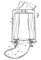
- FIG. 1 shows a filter housing 10 in a detailed view and a housing cover 11.
- a filter element 12 is arranged. This consists of a zigzag-shaped folded filter medium with a front disc 13.
- a sealing ring 14 is glued or welded to the end plate 13.
- the sealing ring bears against a sealing surface 15 of the filter housing 10.
- the sealing surface surrounds the clean air outlet, not shown here.
- the end disk is provided with a tab-shaped projection 16. Between this tab-shaped projection 16 and a support 17, a clamping wedge 18 is inserted.
- the clamping wedge 18 is attached to the housing cover and causes an axial force on the filter insert 12 such that a good sealing effect between the sealing ring 14 and the sealing surface 15 is achieved.
- FIG. 2 shows the overall structure of a filter device in a sectional view. (Identical parts are provided with the same reference numerals.) It can be seen at the right end of the unfiltered air inlet 19 and at the left end of the clean air outlet 20.
- the filter housing 10 is equipped with a filter element 12, the filter element is at the right-hand end with an end plate 21st Mistake. This has a guide projection 22.
- the guide approach engages in a guide cylinder 23 which is fixed to the housing. This storage allows radial displacement and a good tolerance compensation at different filter insert lengths.
- the filter insert is equipped on the left side with an end plate 13. This is provided with a projection 16, which extends over a clean air pipe 24 and provides for the axial guidance of the filter cartridge.
- the sealing ring 14 consists in this embodiment of PUR foam and is connected to the Foamed end disc.
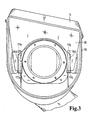
- Figure 3 shows a plan view of the clamping wedge 18 which is rigidly connected to the housing cover 11.
- the projections 16a, 16b on the front disk of the filter insert comprise the clamping wedge 18.
- This clamping wedge 18 is supported on the supports 17a, 17b, so that the clamping forces for the front disk of the filter element can be introduced over a predefined area.
- the filter element can be easily removed from the filter housing and replaced with a new one.
Landscapes
- Chemical & Material Sciences (AREA)
- Engineering & Computer Science (AREA)
- Chemical Kinetics & Catalysis (AREA)
- Physics & Mathematics (AREA)
- Geometry (AREA)
- Combustion & Propulsion (AREA)
- Mechanical Engineering (AREA)
- General Engineering & Computer Science (AREA)
- Filtering Of Dispersed Particles In Gases (AREA)
- Surgical Instruments (AREA)
- Centrifugal Separators (AREA)
- Separation By Low-Temperature Treatments (AREA)
Description
- Die Erfindung betrifft eine Filtereinrichtung nach dem Oberbegriff des unabhängigen Anspruchs 1.
- Eine solche Filtereinrichtung ist bekannt. Üblicherweise wird der Filtereinsatz in der Filtereinrichtung mit einer Spannschraube befestigt, hierzu sind an dem Gehäuse Befestigungselemente vorgesehen. Es besteht bei den bekannten Filtereinsätzen auch die Möglichkeit durch einen Deckel der in axialer Richtung auf das Gehäuse aufgesetzt wird, den Filtereinsatz in dem Gehäuse zu fixieren. Sofern der im wesentlichen zylinderförmig aufgebaute Filtereinsatz unter beengten Platzverhältnissen ein- oder ausgebaut werden muss, kann ein axial gerichtetes Abziehen oder Aufziehen nicht erfolgen. In diesen Fällen ist es erforderlich, den Filtereinsatz aus dem Gehäuse herauszuheben, dass heißt das Gehäuse ist mit einem Deckel verschlossen, der einen Teil der Mantelfläche abdeckt. Der Filtereinsatz kann nach dem Öffnen des Deckels aus dem Gehäuse herausgehoben werden und ein neuer Filtereinsatz ist einsetzbar.
- Ein Problem bei diesem Gehäuseaufbau besteht darin, dass eine Axialverschiebung des Filtereinsatzes zum Abdichten zwischen Rohluft- und Reinluftbereich erforderlich ist. Dieses axiale Verschieben ist nur mit speziellen Schraub- oder Bajonettverschlüssen oder speziellen Aufnahmevorrichtungen für den Filtereinsatz möglich.
- Der Erfindung liegt die Aufgabe zugrunde, eine Filtereinrichtung zu schaffen, bei welcher der Filtereinsatz unter beengten Platzverhältnissen ein und ausgebaut werden kann und ein zuverlässige und einfache Abdichtung zwischen Rohluftbereich und Reinluftbereich gewährt wird.
- Diese Aufgabe wird ausgehend von dem Oberbegriff des unabhängigen Anspruchs 1 durch dessen kennzeichnenden Merkmale gelöst.
- Der wesentliche Vorteil der Erfindung liegt darin, dass ein Spannkeil vorgesehen ist, welcher eine Kraft derart ausübt, dass die Axialdichtung des zylinderförmigen Filtereinsatzes zuverlässig an der gehäusefesten Dichtfläche anliegt. Dieser Spannkeil ist gemäß der Erfindung am Deckel angeordnet. Das Schließen des Deckels bewirkt die Verspannung, dass heißt die Abdichtung des Filtereinsatzes. Das Öffnen des Deckels bewirkt ein Lösen des Filtereinsatzes und damit ein einfaches Austauschen. Die Erfindung sieht vor, dass sich der Spannkeil in eine Lasche des Filtereinsatzes einführen läßt. Zur Abstützung des Spannkeils ist gehäusefest eine Abstützfläche oder ein weiteres Element vorgesehen. Der Spannkeil ist zumindest teilweise keilförmig ausgestaltet, so dass eine einfache Krafteinleitung beim Schließen des Deckels bzw. beim Einführen des Spannkeils möglich ist.
- Eine weitere Ausgestaltung der Erfindung sieht vor, auf der, der Dichtfläche gegenüberliegenden Seite des Filtereinsatzes eine Axialführung vorzusehen, dass heißt, auf dieser Seite stützt sich der Filtereinsatz an dem Gehäuse ab, und ist axialtolerant befestigt.
- Ein Vorteil dieser Lagerung des Filtereinsatzes liegt darin, dass das Filtermedium keine axialen Verspannkräfte aufnehmen muss. Außerdem kann das Filtergehäuse selbst schwächer dimensioniert werden, da dieses nicht in den Kraftfluß eingebunden ist.
- Gemäß einer Ausgestaltung der Erfindung besteht der Filtereinsatz aus einem zick-zack-förmig gefalteten Filterpapier oder Filtervlies, dieses weist eine sehr hohe Staubaufnahmekapazität, gepaart mit einem geringen Durchflußwiderstand auf. Die Stirnendscheiben dieses Filtereinsatzes bestehen aus einem thermoplastischen Kunststoff. Der Filtereinsatz läßt sich damit in einfacher Weise thermisch entsorgen.
- Diese und weitere Merkmale von bevorzugten Weiterbildungen der Erfindung gehen außer aus den Ansprüchen auch aus der Beschreibung und der Zeichnung hervor, wobei die einzelnen Merkmale jeweils für sich allein oder zu mehreren in Form von Unterkombinationen bei der Ausführungsform der Erfindung und auf anderen Gebieten verwirklicht sein und vorteilhafte sowie für sich schutzfähige Ausführungen darstellen können, für die hier Schutz beansprucht wird.
- Weitere Einzelheiten der Erfindung werden in der Zeichnung anhand von schematischen Ausführungsbeispielen beschrieben. Hierbei zeigen
- Figur 1
- die schematische Darstellung eines Details der Filtereinrichtung
- Figur 2
- eine Querschnittdarstellung eines Filtereinsatzes
- Figur 3
- die Draufsichtdarstellung auf den in Figur 2 gezeigten Filtereinsatz
- Die schematische Darstellung in Figur 1 zeigt ein Filtergehäuse 10 in einer Detaildarstellung sowie einen Gehäusedeckel 11. In dem Filtergehäuse ist ein Filterelement 12 angeordnet. Dies besteht aus einem zick-zack-förmig gefalteten Filtermedium mit einer Stirnscheibe 13. Auf diese Stirnscheibe 13 ist ein Dichtungsring 14 aufgeklebt oder mit der Stirnscheibe 13 verschweißt. Der Dichtungsring liegt an einer Dichtfläche 15 des Filtergehäuses 10 an. Die Dichtfläche umschließt den hier nicht dargestellten Reinluftauslass. Die Stirnscheibe ist mit einer laschenförmigen Auskragung 16 versehen. Zwischen dieser laschenförmigen Auskragung 16 und einer Abstützung 17 wird ein Spannkeil 18 eingeschoben. Der Spannkeil 18 ist an dem Gehäusedeckel befestigt und bewirkt eine Axialkraft auf den Filtereinsatz 12 derart, dass eine gute Dichtwirkung zwischen dem Dichtungsring 14 und der Dichtfläche 15 erzielt wird.
- Figur 2 zeigt den Gesamtaufbau einer Filtereinrichtung in einer Schnittdarstellung. (Gleiche Teile sind mit gleichen Bezugszeichen versehen.) Zu erkennen ist an dem rechtsseitigen Ende der Rohlufteinlass 19 und an dem linksseitigen Ende der Reinluftauslass 20. Das Filtergehäuse 10 ist mit einem Filtereinsatz 12 bestückt, der Filtereinsatz ist an dem rechtsseitigen Ende mit einer Endscheibe 21 versehen. Diese weist einen Führungsansatz 22 auf. Der Führungsansatz greift in einen Führungszylinder 23, welcher am Gehäuse befestigt ist. Diese Lagerung ermöglicht eine radiale Verschiebbarkeit und einen guten Toleranzausgleich bei unterschiedlichen Filtereinsatzlängen. Der Filtereinsatz ist an der linken Seite mit einer Stirnscheibe 13 ausgestattet. Diese ist mit einer Auskragung 16 versehen, welche sich über einen Reinluftstutzen 24 erstreckt und für die axiale Führung des Filtereinsatzes sorgt. Der Dichtungsring 14 besteht in diesem Ausführungsbeispiel aus PUR-Schaum und ist an die Endscheibe angeschäumt. Am Gehäuse befindet sich eine Abstützung 17. Zwischen Abstützung 17 und Auskragung 16 ist ein Spannkeil 18 eingefügt. Dieser Spannkeil 18 zieht den kompletten Filtereinsatz nach links gegen den Reinluftstutzen 24 und bewirkt eine zuverlässige Abdichtung zwischen Reinluft und Rohluft.
- Figur 3 zeigt eine Draufsicht auf den Spannkeil 18 der mit dem Gehäusedeckel 11 starr verbunden ist. Die Auskragungen 16a, 16b an der Stirnscheibe des Filtereinsatzes umfassen den Spannkeil 18. Dieser Spannkeil 18 stützt sich an den Abstützungen 17a, 17b ab , so dass über einen vordefinierten Bereich die Spannkräfte für die Stirnscheibe des Filterelements eingeleitet werden können. Beim Abnehmen des Gehäusedeckels 11 wird der Spannkeil 18 ebenfalls mit abgezogen. Das Filterelement kann in einfacher Weise aus dem Filtergehäuse herausgenommen und durch ein neues ersetzt werden.
Claims (5)
- Filtereinrichtung insbesondere zur Filtration der Ansaugluft einer Brennkraftmaschine bestehend aus einem Gehäuse (10) mit einem Rohlufteinlass (19) einem Reinluftauslass (20) und einem in dem Gehäuse angeordneten austauschbaren Filtereinsatz, (12) welcher den Rohluftbereich des Gehäuses von dem Reinluftbereich trennt und welcher im wesentlichen zylinderförmig gestaltet ist, wobei an wenigstens einer Stirnscheibe (13) eine Axialdichtung vorgesehen ist, welche in Verbindung mit einer Dichtfläche des Gehäuses (10) die Abdichtung zwischen Rohluftbereich und Reinluftbereich bewirkt, ein Spannkeil (18) vorgesehen ist, welcher eine Kraft auf den Filtereinsatz (12) ausübt, derart, dass die Axialdichtung (14) zuverlässig an der Dichtfläche (15) des Gehäuses (10) anliegt dadurch gekennzeichnet dass, der Filtereinsatz (12) an der Stirnscheibe (13) wenigstens eine Lasche (16) aufweist und der Spannkeil (18) an dieser Lasche (16) entlang gleitet, wobei sich der Spannkeil (18) an einer gehäusefesten Abstützung (17) oder an der Dichtfläche (15) des Gehäuses (10) abstützt.
- Filtereinrichtung nach Anspruch 1, dadurch gekennzeichnet, daß der Spannkeil (18) mit einem Deckel (11) für das Gehäuse (10) verbunden ist und beim Schließen des Deckels (11) eine Verspannung des Filtereinsatzes (12) bewirkt.
- Filtereinrichtung nach einem der vorherigen Ansprüche, dadurch gekennzeichnet, daß auf der Dichtseite gegenüberliegenden Seite des Filtereinsatzes (12) dieser am Gehäuse (10) axial geführt ist.
- Filtereinrichtung nach einem der vorherigen Ansprüche, dadurch gekennzeichnet, daß der Filtereinsatz (12) aus einem zick-zack-förmig gefalteten Filtermedium, insbesondere Filterpapier oder Filtervlies besteht, welches selbsttragend ist und an den Stirnseiten mit thermoplastischen Stirnscheiben (13) versehen ist, wobei die Axialdichtung (14) über eine PUR-Schaumdichtung an der, dem Reinluftauslass (20) zugewandten Stirnscheibe (13) erfolgt.
- Filtereinsatz insbesondere zur Verwendung in einer Filtereinrichtung nach Anspruch 1, bestehend aus einem zick-zack-förmig gefalteten Filterpapier oder Filtervlies, welches selbsttragend ist und an den Stirnseiten mit thermoplastischen Stirnscheiben (13) versehen ist, wobei an wenigstens einer Stirnscheiben (13) wenigstens eine Lasche (16) vorgesehen ist in welcher ein Spannkeil (18) eingreift zur Axialverschiebung des Filtereinsatzes (12).
Applications Claiming Priority (3)
| Application Number | Priority Date | Filing Date | Title |
|---|---|---|---|
| DE10026437A DE10026437A1 (de) | 2000-05-29 | 2000-05-29 | Filtereinrichtung |
| DE10026437 | 2000-05-29 | ||
| PCT/EP2001/005386 WO2001091884A1 (de) | 2000-05-29 | 2001-05-11 | Filtereinrichtung |
Publications (2)
| Publication Number | Publication Date |
|---|---|
| EP1286750A1 EP1286750A1 (de) | 2003-03-05 |
| EP1286750B1 true EP1286750B1 (de) | 2007-04-04 |
Family
ID=7643863
Family Applications (1)
| Application Number | Title | Priority Date | Filing Date |
|---|---|---|---|
| EP01947274A Expired - Lifetime EP1286750B1 (de) | 2000-05-29 | 2001-05-11 | Filtereinrichtung |
Country Status (7)
| Country | Link |
|---|---|
| US (1) | US6736874B2 (de) |
| EP (1) | EP1286750B1 (de) |
| JP (1) | JP4621406B2 (de) |
| AT (1) | ATE358522T1 (de) |
| DE (2) | DE10026437A1 (de) |
| ES (1) | ES2283420T3 (de) |
| WO (1) | WO2001091884A1 (de) |
Cited By (2)
| Publication number | Priority date | Publication date | Assignee | Title |
|---|---|---|---|---|
| EP2754880A1 (de) | 2013-01-15 | 2014-07-16 | MAHLE International GmbH | Filtereinrichtung |
| US10359011B2 (en) | 2013-05-22 | 2019-07-23 | Donaldson Company, Inc. | Vertical air intake system; air cleaner; and filter element |
Families Citing this family (41)
| Publication number | Priority date | Publication date | Assignee | Title |
|---|---|---|---|---|
| US6652614B2 (en) * | 2000-12-04 | 2003-11-25 | Donaldson Company, Inc. | Filter system; element configuration; and methods |
| US7537631B2 (en) | 2002-10-28 | 2009-05-26 | Donaldson Company, Inc. | Filter cartridges; air cleaners; and methods |
| JP4443513B2 (ja) | 2002-10-28 | 2010-03-31 | ドナルドソン カンパニー,インコーポレイティド | エアクリーナ、交換可能なフィルタ・カートリッジと方法 |
| EP1722880B2 (de) | 2004-02-17 | 2018-10-03 | Donaldson Company, Inc. | Luftreinigeranordnungen, wartungsfähige filterelemente und verfahren |
| DE102005010443A1 (de) * | 2004-09-21 | 2006-03-23 | Mann + Hummel Gmbh | Filterelement |
| WO2006078587A2 (en) * | 2005-01-18 | 2006-07-27 | Donaldson Company, Inc. | Fluid filter |
| EP1754525B1 (de) | 2005-08-16 | 2011-01-19 | Donaldson Company, Inc. | Luftreiniger mit verdrehsicherer Anordnung und Verfahren |
| DE202005020099U1 (de) * | 2005-12-23 | 2007-05-10 | Hengst Gmbh & Co.Kg | Luftfilter und Filtereinsatz |
| DE202006005012U1 (de) | 2006-03-29 | 2007-08-09 | Hengst Gmbh & Co.Kg | Luftfilter und Filtereinsatz |
| DE202006011991U1 (de) * | 2006-08-03 | 2007-12-06 | Mann + Hummel Gmbh | Luftfiltereinheit mit einem radial geteilten Gehäuse |
| EP2664372A1 (de) | 2006-10-06 | 2013-11-20 | Donaldson Company, Inc. | Luftreiniger, auswechselbare Filterpatronen und Verfahren |
| US7597735B2 (en) * | 2006-12-21 | 2009-10-06 | Cummins Filtration Ip Inc. | Apparatus and system for uniform sealing force in an air filter assembly |
| WO2008124437A2 (en) * | 2007-04-03 | 2008-10-16 | Donaldson Company, Inc. | Air cleaner; air filter cartridge and method of manufacturing |
| CN103721492B (zh) * | 2007-06-14 | 2016-01-06 | 唐纳森公司 | 曲轴箱通风过滤器装置、部件和方法 |
| US8292984B2 (en) | 2007-07-20 | 2012-10-23 | Donaldson Company, Inc. | Air cleaner arrangments with end support for cartridge; components; and, methods |
| US8066791B2 (en) | 2007-07-20 | 2011-11-29 | Donaldson Company, Inc. | Air cleaner arrangements with internal and external support for cartridge; components; and, methods |
| US7972406B2 (en) * | 2007-08-09 | 2011-07-05 | Honeywell International Inc. | Diesel particulate filter and method of making |
| DE202007014822U1 (de) * | 2007-10-02 | 2009-02-19 | Mann+Hummel Gmbh | Filterelement Zackendichtung |
| DE202007013822U1 (de) * | 2007-10-02 | 2009-02-19 | Mann+Hummel Gmbh | Filterelement und Filtersystem |
| DE202007014821U1 (de) * | 2007-10-02 | 2009-02-26 | Mann+Hummel Gmbh | Filterelement V-Dichtung |
| MX342896B (es) | 2007-11-15 | 2016-10-18 | Donaldson Company Inc * | Arreglos de filtro de aire; montajes; y, metodos. |
| DE202008015440U1 (de) † | 2008-11-20 | 2010-04-08 | Mann+Hummel Gmbh | Ansaugluftfilter für Verbrennungskraftmaschinen |
| DE102008063720A1 (de) | 2008-12-19 | 2010-06-24 | A. Kayser Automotive Systems Gmbh | Filtereinrichtung |
| CN103442782A (zh) | 2011-02-25 | 2013-12-11 | 唐纳森公司 | 空气过滤器滤芯、其部件和空气滤清器组件 |
| DE102012016558A1 (de) * | 2012-08-22 | 2014-02-27 | Mann+Hummel Gmbh | Filtereinrichtung, insbesondere zur Gasfiltration |
| CN104540573B (zh) * | 2012-08-22 | 2017-10-24 | 曼·胡默尔有限公司 | 尤其用于气体过滤的过滤装置 |
| EP2888023B1 (de) | 2012-08-22 | 2019-03-20 | MANN+HUMMEL GmbH | Filtereinrichtung, insbesondere zur gasfiltration |
| US9067161B2 (en) | 2012-11-29 | 2015-06-30 | Donaldson Company, Inc. | Filter cartridges; features and methods of assembly; air cleaner assemblies; and, filter cartridge combinations |
| DE102013203096A1 (de) | 2013-02-26 | 2014-08-28 | Mahle International Gmbh | Saugmodulkombination |
| US10753321B2 (en) * | 2013-06-20 | 2020-08-25 | Mann+Hummel Gmbh | Hollow filter element, filter housing, and filter |
| US10239005B2 (en) * | 2013-06-20 | 2019-03-26 | Mann+Hummel Gmbh | Filter housing, hollow filter element and filter |
| DE102014006850B4 (de) * | 2013-06-20 | 2022-08-25 | Mann+Hummel Gmbh | Filtergehäuse, Hohlfilterelement und Filter |
| US9726123B2 (en) * | 2013-06-20 | 2017-08-08 | Mann+Hummel Gmbh | Air filter, filter element and filter housing of an air filter |
| US10436155B2 (en) * | 2013-06-20 | 2019-10-08 | Mann+Hummel Gmbh | Air filter, filter element and filter housing of an air filter |
| DE102013011813B4 (de) * | 2013-07-16 | 2022-07-28 | Mann+Hummel Gmbh | Filtereinrichtung und Filterelement |
| DE112015002635T5 (de) | 2014-06-03 | 2017-03-09 | Cummins Filtration Ip, Inc. | Filterbaugruppe mit Nockenschloss-Filter-Schnittstelle |
| EP3223927B1 (de) * | 2014-11-24 | 2020-05-13 | Mann+Hummel GmbH | Filtervorrichtung und wartungverfahren für die filtervorrichtung |
| KR101776494B1 (ko) * | 2016-04-28 | 2017-09-07 | 현대자동차주식회사 | 라운드형 차량용 에어필터와 이를 포함하는 차량용 에어클리너 어셈블리 |
| EP3401000A1 (de) | 2017-05-09 | 2018-11-14 | Donaldson Company, Inc. | Adapter und luftfilterpatrone zur verwendung mit solch einem adapter |
| DE102022119072A1 (de) | 2022-07-29 | 2024-02-01 | Mann+Hummel Gmbh | Luftfilter |
| DE102024129735B3 (de) * | 2024-10-14 | 2026-02-19 | Daimler Truck AG | Luftfilter für einen Kraftwagen |
Family Cites Families (22)
| Publication number | Priority date | Publication date | Assignee | Title |
|---|---|---|---|---|
| US1712947A (en) * | 1926-12-04 | 1929-05-14 | Ac Spark Plug Co | Air cleaner |
| US2134601A (en) * | 1937-06-26 | 1938-10-25 | New York Air Brake Co | Air filter |
| US2962121A (en) * | 1958-03-26 | 1960-11-29 | Dollinger Corp | Filter |
| US3745753A (en) * | 1970-04-27 | 1973-07-17 | United Filtration Corp | Air cleaner |
| DE3271301D1 (en) * | 1981-02-23 | 1986-07-03 | Nippon Denso Co | Fluid cleaner systems |
| JPS5956366U (ja) * | 1982-10-08 | 1984-04-12 | 本田技研工業株式会社 | エアクリ−ナ |
| US4498914A (en) * | 1983-03-03 | 1985-02-12 | Donaldson Company, Inc. | Filter apparatus including apparatus for clamping an air filter element in a filter housing |
| US4775469A (en) * | 1987-08-12 | 1988-10-04 | Tri-Clover, Inc. | Filter bag sealing device |
| US4822386A (en) * | 1987-11-27 | 1989-04-18 | United Technologies Corporation | Filter replacement mechanism |
| US4841628A (en) * | 1987-12-21 | 1989-06-27 | United Technologies Corporation | Filter replacement mechanism |
| DE4031014C2 (de) * | 1989-04-06 | 1993-11-18 | Mann & Hummel Filter | Ansaugluftfilter für Brennkraftmaschinen |
| DE3911153A1 (de) * | 1989-04-06 | 1990-10-11 | Mann & Hummel Filter | Ansaugluftfilter fuer brennkraftmaschinen |
| DE4024898A1 (de) * | 1990-08-06 | 1992-02-13 | Mann & Hummel Filter | Ansaugluftfilter fuer die verbrennungskraftmaschine eines fahrzeugs |
| US5320657A (en) * | 1993-04-30 | 1994-06-14 | Dana Corporation | Staggered short pleat air filter |
| JP2603544Y2 (ja) * | 1993-06-30 | 2000-03-15 | 株式会社テネックス | エアクリーナ |
| DE19624523A1 (de) * | 1996-06-20 | 1998-01-02 | Mann & Hummel Filter | Filter |
| DE19638791A1 (de) * | 1996-09-21 | 1998-03-26 | Mann & Hummel Filter | Luftfilter, insbesondere Ansaugluftfilter für eine Brennkraftmaschine |
| DE19730817A1 (de) * | 1997-07-18 | 1999-01-21 | Knecht Filterwerke Gmbh | Plattenförmiges Filterelement |
| US6051042A (en) * | 1997-09-12 | 2000-04-18 | Donaldson Company, Inc. | Air cleaner assembly |
| DE19742271C1 (de) * | 1997-09-25 | 1999-06-02 | Freudenberg Carl Fa | Filtereinsatz |
| US6299661B1 (en) * | 1999-05-12 | 2001-10-09 | Siemens Canada Limited | Twist fit connection for air cleaners |
| US6436162B1 (en) * | 2000-03-22 | 2002-08-20 | Nelson Industries, Inc. | Twist and lock filter housing with anti-rotation stop |
-
2000
- 2000-05-29 DE DE10026437A patent/DE10026437A1/de not_active Withdrawn
-
2001
- 2001-05-11 AT AT01947274T patent/ATE358522T1/de active
- 2001-05-11 ES ES01947274T patent/ES2283420T3/es not_active Expired - Lifetime
- 2001-05-11 WO PCT/EP2001/005386 patent/WO2001091884A1/de not_active Ceased
- 2001-05-11 EP EP01947274A patent/EP1286750B1/de not_active Expired - Lifetime
- 2001-05-11 DE DE50112292T patent/DE50112292D1/de not_active Expired - Lifetime
- 2001-05-11 JP JP2001587890A patent/JP4621406B2/ja not_active Expired - Lifetime
-
2002
- 2002-11-27 US US10/305,388 patent/US6736874B2/en not_active Expired - Lifetime
Cited By (4)
| Publication number | Priority date | Publication date | Assignee | Title |
|---|---|---|---|---|
| EP2754880A1 (de) | 2013-01-15 | 2014-07-16 | MAHLE International GmbH | Filtereinrichtung |
| DE102013200511A1 (de) | 2013-01-15 | 2014-07-17 | Mahle International Gmbh | Filtereinrichtung |
| US10359011B2 (en) | 2013-05-22 | 2019-07-23 | Donaldson Company, Inc. | Vertical air intake system; air cleaner; and filter element |
| US12060858B2 (en) | 2013-05-22 | 2024-08-13 | Donaldson Company, Inc. | Vertical air intake system; air cleaner; and filter element |
Also Published As
| Publication number | Publication date |
|---|---|
| DE50112292D1 (de) | 2007-05-16 |
| JP4621406B2 (ja) | 2011-01-26 |
| WO2001091884A1 (de) | 2001-12-06 |
| US20030121242A1 (en) | 2003-07-03 |
| JP2003534497A (ja) | 2003-11-18 |
| EP1286750A1 (de) | 2003-03-05 |
| DE10026437A1 (de) | 2001-12-06 |
| US6736874B2 (en) | 2004-05-18 |
| ATE358522T1 (de) | 2007-04-15 |
| ES2283420T3 (es) | 2007-11-01 |
Similar Documents
| Publication | Publication Date | Title |
|---|---|---|
| WO2001091884A1 (de) | Filtereinrichtung | |
| EP1015751B1 (de) | Luftfilter | |
| EP0401329B1 (de) | Ölfilter für verbrennungsmotoren | |
| EP1191994B1 (de) | Luftfilter für eine Brennkraftmaschine | |
| EP0934108B1 (de) | Filter, insbesondere zur filtrierung des schmieröls einer brennkraftmaschine | |
| EP0951329B1 (de) | Filter, insbesondere für das schmieröl einer brennkraftmaschine | |
| EP0650751A2 (de) | Filtereinrichtung | |
| DE9312051U1 (de) | Filtereinsatz für ein Filter zur Filterung von flüssigen oder gasförmigen Medien | |
| EP2227307A1 (de) | Filterelement und filtersystem | |
| EP2742986A1 (de) | Luftfiltersystem, Luftfilterelement und Verfahren zum Austausch eines Luftfilterelements | |
| DE112015004116T5 (de) | Axialströmungs-Luftfilterelement | |
| EP1159998B1 (de) | Flüssigkeitsfilter | |
| EP1982754A2 (de) | Filtersystem | |
| DE102014006852A1 (de) | Hohlfilterelement, Filtergehäuse und Filter | |
| EP1736227B1 (de) | Filterdichtsystem | |
| EP1113853A1 (de) | Flüssigkeitsfilter, insbesondere für öl oder kraftstoff einer brennkraftmaschine | |
| WO2000025016A1 (de) | Filter, insbesondere für die ansaugluft einer brennkraftmaschine | |
| EP1216743A1 (de) | Filtersystem | |
| EP0885044B1 (de) | Konischer fluidfilter | |
| DE19505583A1 (de) | Filter, insbesondere für die Luft des Innenraums eines Fahrzeugs | |
| EP1712266A1 (de) | Filtersystem | |
| DE102007006811A1 (de) | Vorrichtung zum Filtrieren einer thermoplastischen Kunststoffschmelze | |
| DE19619770A1 (de) | Filter, insbesondere für die Frischluft für Fahrgastzellen von Fahrzeugen | |
| EP0919270A1 (de) | Filtereinrichtung | |
| EP0152903A2 (de) | Filtervorrichtung in Segmentbauweise |
Legal Events
| Date | Code | Title | Description |
|---|---|---|---|
| PUAI | Public reference made under article 153(3) epc to a published international application that has entered the european phase |
Free format text: ORIGINAL CODE: 0009012 |
|
| AK | Designated contracting states |
Kind code of ref document: A1 Designated state(s): AT BE CH CY DE DK ES FI FR GB GR IE IT LI LU MC NL PT SE TR |
|
| 17P | Request for examination filed |
Effective date: 20020906 |
|
| RAP1 | Party data changed (applicant data changed or rights of an application transferred) |
Owner name: MANN + HUMMEL GMBH |
|
| 17Q | First examination report despatched |
Effective date: 20050310 |
|
| GRAP | Despatch of communication of intention to grant a patent |
Free format text: ORIGINAL CODE: EPIDOSNIGR1 |
|
| GRAS | Grant fee paid |
Free format text: ORIGINAL CODE: EPIDOSNIGR3 |
|
| GRAA | (expected) grant |
Free format text: ORIGINAL CODE: 0009210 |
|
| AK | Designated contracting states |
Kind code of ref document: B1 Designated state(s): AT BE CH CY DE DK ES FI FR GB GR IE IT LI LU MC NL PT SE TR |
|
| PG25 | Lapsed in a contracting state [announced via postgrant information from national office to epo] |
Ref country code: FI Free format text: LAPSE BECAUSE OF FAILURE TO SUBMIT A TRANSLATION OF THE DESCRIPTION OR TO PAY THE FEE WITHIN THE PRESCRIBED TIME-LIMIT Effective date: 20070404 |
|
| REG | Reference to a national code |
Ref country code: GB Ref legal event code: FG4D Free format text: NOT ENGLISH |
|
| GBT | Gb: translation of ep patent filed (gb section 77(6)(a)/1977) |
Effective date: 20070404 |
|
| REG | Reference to a national code |
Ref country code: CH Ref legal event code: EP |
|
| REF | Corresponds to: |
Ref document number: 50112292 Country of ref document: DE Date of ref document: 20070516 Kind code of ref document: P |
|
| REG | Reference to a national code |
Ref country code: IE Ref legal event code: FG4D Free format text: LANGUAGE OF EP DOCUMENT: GERMAN |
|
| PG25 | Lapsed in a contracting state [announced via postgrant information from national office to epo] |
Ref country code: SE Free format text: LAPSE BECAUSE OF FAILURE TO SUBMIT A TRANSLATION OF THE DESCRIPTION OR TO PAY THE FEE WITHIN THE PRESCRIBED TIME-LIMIT Effective date: 20070704 |
|
| PG25 | Lapsed in a contracting state [announced via postgrant information from national office to epo] |
Ref country code: PT Free format text: LAPSE BECAUSE OF FAILURE TO SUBMIT A TRANSLATION OF THE DESCRIPTION OR TO PAY THE FEE WITHIN THE PRESCRIBED TIME-LIMIT Effective date: 20070904 |
|
| ET | Fr: translation filed | ||
| NLV1 | Nl: lapsed or annulled due to failure to fulfill the requirements of art. 29p and 29m of the patents act | ||
| REG | Reference to a national code |
Ref country code: ES Ref legal event code: FG2A Ref document number: 2283420 Country of ref document: ES Kind code of ref document: T3 |
|
| REG | Reference to a national code |
Ref country code: IE Ref legal event code: FD4D |
|
| BERE | Be: lapsed |
Owner name: MANN + HUMMEL G.M.B.H. Effective date: 20070531 |
|
| REG | Reference to a national code |
Ref country code: CH Ref legal event code: PL |
|
| PG25 | Lapsed in a contracting state [announced via postgrant information from national office to epo] |
Ref country code: NL Free format text: LAPSE BECAUSE OF FAILURE TO SUBMIT A TRANSLATION OF THE DESCRIPTION OR TO PAY THE FEE WITHIN THE PRESCRIBED TIME-LIMIT Effective date: 20070404 Ref country code: IE Free format text: LAPSE BECAUSE OF FAILURE TO SUBMIT A TRANSLATION OF THE DESCRIPTION OR TO PAY THE FEE WITHIN THE PRESCRIBED TIME-LIMIT Effective date: 20070404 Ref country code: MC Free format text: LAPSE BECAUSE OF NON-PAYMENT OF DUE FEES Effective date: 20070531 Ref country code: DK Free format text: LAPSE BECAUSE OF FAILURE TO SUBMIT A TRANSLATION OF THE DESCRIPTION OR TO PAY THE FEE WITHIN THE PRESCRIBED TIME-LIMIT Effective date: 20070404 |
|
| PLBE | No opposition filed within time limit |
Free format text: ORIGINAL CODE: 0009261 |
|
| STAA | Information on the status of an ep patent application or granted ep patent |
Free format text: STATUS: NO OPPOSITION FILED WITHIN TIME LIMIT |
|
| PG25 | Lapsed in a contracting state [announced via postgrant information from national office to epo] |
Ref country code: LI Free format text: LAPSE BECAUSE OF NON-PAYMENT OF DUE FEES Effective date: 20070531 Ref country code: CH Free format text: LAPSE BECAUSE OF NON-PAYMENT OF DUE FEES Effective date: 20070531 |
|
| 26N | No opposition filed |
Effective date: 20080107 |
|
| PG25 | Lapsed in a contracting state [announced via postgrant information from national office to epo] |
Ref country code: BE Free format text: LAPSE BECAUSE OF NON-PAYMENT OF DUE FEES Effective date: 20070531 |
|
| PG25 | Lapsed in a contracting state [announced via postgrant information from national office to epo] |
Ref country code: GR Free format text: LAPSE BECAUSE OF FAILURE TO SUBMIT A TRANSLATION OF THE DESCRIPTION OR TO PAY THE FEE WITHIN THE PRESCRIBED TIME-LIMIT Effective date: 20070705 |
|
| PG25 | Lapsed in a contracting state [announced via postgrant information from national office to epo] |
Ref country code: CY Free format text: LAPSE BECAUSE OF FAILURE TO SUBMIT A TRANSLATION OF THE DESCRIPTION OR TO PAY THE FEE WITHIN THE PRESCRIBED TIME-LIMIT Effective date: 20070404 |
|
| PG25 | Lapsed in a contracting state [announced via postgrant information from national office to epo] |
Ref country code: LU Free format text: LAPSE BECAUSE OF NON-PAYMENT OF DUE FEES Effective date: 20070511 |
|
| PGFP | Annual fee paid to national office [announced via postgrant information from national office to epo] |
Ref country code: IT Payment date: 20140529 Year of fee payment: 14 |
|
| PG25 | Lapsed in a contracting state [announced via postgrant information from national office to epo] |
Ref country code: IT Free format text: LAPSE BECAUSE OF NON-PAYMENT OF DUE FEES Effective date: 20150511 |
|
| REG | Reference to a national code |
Ref country code: FR Ref legal event code: PLFP Year of fee payment: 16 |
|
| REG | Reference to a national code |
Ref country code: FR Ref legal event code: PLFP Year of fee payment: 17 |
|
| REG | Reference to a national code |
Ref country code: FR Ref legal event code: PLFP Year of fee payment: 18 |
|
| REG | Reference to a national code |
Ref country code: DE Ref legal event code: R081 Ref document number: 50112292 Country of ref document: DE Owner name: MANN+HUMMEL GMBH, DE Free format text: FORMER OWNER: MANN + HUMMEL GMBH, 71638 LUDWIGSBURG, DE |
|
| PGFP | Annual fee paid to national office [announced via postgrant information from national office to epo] |
Ref country code: TR Payment date: 20200511 Year of fee payment: 20 Ref country code: DE Payment date: 20200520 Year of fee payment: 20 Ref country code: FR Payment date: 20200522 Year of fee payment: 20 |
|
| PGFP | Annual fee paid to national office [announced via postgrant information from national office to epo] |
Ref country code: GB Payment date: 20200527 Year of fee payment: 20 |
|
| PGFP | Annual fee paid to national office [announced via postgrant information from national office to epo] |
Ref country code: AT Payment date: 20200522 Year of fee payment: 20 |
|
| PGFP | Annual fee paid to national office [announced via postgrant information from national office to epo] |
Ref country code: ES Payment date: 20200728 Year of fee payment: 20 |
|
| REG | Reference to a national code |
Ref country code: DE Ref legal event code: R071 Ref document number: 50112292 Country of ref document: DE |
|
| REG | Reference to a national code |
Ref country code: GB Ref legal event code: PE20 Expiry date: 20210510 |
|
| REG | Reference to a national code |
Ref country code: AT Ref legal event code: MK07 Ref document number: 358522 Country of ref document: AT Kind code of ref document: T Effective date: 20210511 |
|
| PG25 | Lapsed in a contracting state [announced via postgrant information from national office to epo] |
Ref country code: GB Free format text: LAPSE BECAUSE OF EXPIRATION OF PROTECTION Effective date: 20210510 |
|
| REG | Reference to a national code |
Ref country code: ES Ref legal event code: FD2A Effective date: 20220128 |
|
| PG25 | Lapsed in a contracting state [announced via postgrant information from national office to epo] |
Ref country code: ES Free format text: LAPSE BECAUSE OF EXPIRATION OF PROTECTION Effective date: 20210512 |