EP1285977A2 - Vorrichtung und Verfahren zum Isolieren einer Dichtung in einer Prozesskammer - Google Patents
Vorrichtung und Verfahren zum Isolieren einer Dichtung in einer Prozesskammer Download PDFInfo
- Publication number
- EP1285977A2 EP1285977A2 EP02255775A EP02255775A EP1285977A2 EP 1285977 A2 EP1285977 A2 EP 1285977A2 EP 02255775 A EP02255775 A EP 02255775A EP 02255775 A EP02255775 A EP 02255775A EP 1285977 A2 EP1285977 A2 EP 1285977A2
- Authority
- EP
- European Patent Office
- Prior art keywords
- process chamber
- flange
- cooling tube
- seal
- glass
- Prior art date
- Legal status (The legal status is an assumption and is not a legal conclusion. Google has not performed a legal analysis and makes no representation as to the accuracy of the status listed.)
- Withdrawn
Links
Images


Classifications
-
- C—CHEMISTRY; METALLURGY
- C23—COATING METALLIC MATERIAL; COATING MATERIAL WITH METALLIC MATERIAL; CHEMICAL SURFACE TREATMENT; DIFFUSION TREATMENT OF METALLIC MATERIAL; COATING BY VACUUM EVAPORATION, BY SPUTTERING, BY ION IMPLANTATION OR BY CHEMICAL VAPOUR DEPOSITION, IN GENERAL; INHIBITING CORROSION OF METALLIC MATERIAL OR INCRUSTATION IN GENERAL
- C23C—COATING METALLIC MATERIAL; COATING MATERIAL WITH METALLIC MATERIAL; SURFACE TREATMENT OF METALLIC MATERIAL BY DIFFUSION INTO THE SURFACE, BY CHEMICAL CONVERSION OR SUBSTITUTION; COATING BY VACUUM EVAPORATION, BY SPUTTERING, BY ION IMPLANTATION OR BY CHEMICAL VAPOUR DEPOSITION, IN GENERAL
- C23C16/00—Chemical coating by decomposition of gaseous compounds, without leaving reaction products of surface material in the coating, i.e. chemical vapour deposition [CVD] processes
- C23C16/44—Chemical coating by decomposition of gaseous compounds, without leaving reaction products of surface material in the coating, i.e. chemical vapour deposition [CVD] processes characterised by the method of coating
- C23C16/4401—Means for minimising impurities, e.g. dust, moisture or residual gas, in the reaction chamber
- C23C16/4409—Means for minimising impurities, e.g. dust, moisture or residual gas, in the reaction chamber characterised by sealing means
-
- H—ELECTRICITY
- H10—SEMICONDUCTOR DEVICES; ELECTRIC SOLID-STATE DEVICES NOT OTHERWISE PROVIDED FOR
- H10P—GENERIC PROCESSES OR APPARATUS FOR THE MANUFACTURE OR TREATMENT OF DEVICES COVERED BY CLASS H10
- H10P95/00—Generic processes or apparatus for manufacture or treatments not covered by the other groups of this subclass
-
- C—CHEMISTRY; METALLURGY
- C23—COATING METALLIC MATERIAL; COATING MATERIAL WITH METALLIC MATERIAL; CHEMICAL SURFACE TREATMENT; DIFFUSION TREATMENT OF METALLIC MATERIAL; COATING BY VACUUM EVAPORATION, BY SPUTTERING, BY ION IMPLANTATION OR BY CHEMICAL VAPOUR DEPOSITION, IN GENERAL; INHIBITING CORROSION OF METALLIC MATERIAL OR INCRUSTATION IN GENERAL
- C23C—COATING METALLIC MATERIAL; COATING MATERIAL WITH METALLIC MATERIAL; SURFACE TREATMENT OF METALLIC MATERIAL BY DIFFUSION INTO THE SURFACE, BY CHEMICAL CONVERSION OR SUBSTITUTION; COATING BY VACUUM EVAPORATION, BY SPUTTERING, BY ION IMPLANTATION OR BY CHEMICAL VAPOUR DEPOSITION, IN GENERAL
- C23C16/00—Chemical coating by decomposition of gaseous compounds, without leaving reaction products of surface material in the coating, i.e. chemical vapour deposition [CVD] processes
- C23C16/44—Chemical coating by decomposition of gaseous compounds, without leaving reaction products of surface material in the coating, i.e. chemical vapour deposition [CVD] processes characterised by the method of coating
- C23C16/4401—Means for minimising impurities, e.g. dust, moisture or residual gas, in the reaction chamber
-
- C—CHEMISTRY; METALLURGY
- C23—COATING METALLIC MATERIAL; COATING MATERIAL WITH METALLIC MATERIAL; CHEMICAL SURFACE TREATMENT; DIFFUSION TREATMENT OF METALLIC MATERIAL; COATING BY VACUUM EVAPORATION, BY SPUTTERING, BY ION IMPLANTATION OR BY CHEMICAL VAPOUR DEPOSITION, IN GENERAL; INHIBITING CORROSION OF METALLIC MATERIAL OR INCRUSTATION IN GENERAL
- C23C—COATING METALLIC MATERIAL; COATING MATERIAL WITH METALLIC MATERIAL; SURFACE TREATMENT OF METALLIC MATERIAL BY DIFFUSION INTO THE SURFACE, BY CHEMICAL CONVERSION OR SUBSTITUTION; COATING BY VACUUM EVAPORATION, BY SPUTTERING, BY ION IMPLANTATION OR BY CHEMICAL VAPOUR DEPOSITION, IN GENERAL
- C23C16/00—Chemical coating by decomposition of gaseous compounds, without leaving reaction products of surface material in the coating, i.e. chemical vapour deposition [CVD] processes
- C23C16/44—Chemical coating by decomposition of gaseous compounds, without leaving reaction products of surface material in the coating, i.e. chemical vapour deposition [CVD] processes characterised by the method of coating
- C23C16/4411—Cooling of the reaction chamber walls
-
- C—CHEMISTRY; METALLURGY
- C23—COATING METALLIC MATERIAL; COATING MATERIAL WITH METALLIC MATERIAL; CHEMICAL SURFACE TREATMENT; DIFFUSION TREATMENT OF METALLIC MATERIAL; COATING BY VACUUM EVAPORATION, BY SPUTTERING, BY ION IMPLANTATION OR BY CHEMICAL VAPOUR DEPOSITION, IN GENERAL; INHIBITING CORROSION OF METALLIC MATERIAL OR INCRUSTATION IN GENERAL
- C23C—COATING METALLIC MATERIAL; COATING MATERIAL WITH METALLIC MATERIAL; SURFACE TREATMENT OF METALLIC MATERIAL BY DIFFUSION INTO THE SURFACE, BY CHEMICAL CONVERSION OR SUBSTITUTION; COATING BY VACUUM EVAPORATION, BY SPUTTERING, BY ION IMPLANTATION OR BY CHEMICAL VAPOUR DEPOSITION, IN GENERAL
- C23C16/00—Chemical coating by decomposition of gaseous compounds, without leaving reaction products of surface material in the coating, i.e. chemical vapour deposition [CVD] processes
- C23C16/44—Chemical coating by decomposition of gaseous compounds, without leaving reaction products of surface material in the coating, i.e. chemical vapour deposition [CVD] processes characterised by the method of coating
- C23C16/455—Chemical coating by decomposition of gaseous compounds, without leaving reaction products of surface material in the coating, i.e. chemical vapour deposition [CVD] processes characterised by the method of coating characterised by the method used for introducing gases into reaction chamber or for modifying gas flows in reaction chamber
- C23C16/45563—Gas nozzles
- C23C16/4557—Heated nozzles
-
- H—ELECTRICITY
- H10—SEMICONDUCTOR DEVICES; ELECTRIC SOLID-STATE DEVICES NOT OTHERWISE PROVIDED FOR
- H10P—GENERIC PROCESSES OR APPARATUS FOR THE MANUFACTURE OR TREATMENT OF DEVICES COVERED BY CLASS H10
- H10P72/00—Handling or holding of wafers, substrates or devices during manufacture or treatment thereof
- H10P72/04—Apparatus for manufacture or treatment
- H10P72/0431—Apparatus for thermal treatment
- H10P72/0434—Apparatus for thermal treatment mainly by convection
-
- H—ELECTRICITY
- H10—SEMICONDUCTOR DEVICES; ELECTRIC SOLID-STATE DEVICES NOT OTHERWISE PROVIDED FOR
- H10P—GENERIC PROCESSES OR APPARATUS FOR THE MANUFACTURE OR TREATMENT OF DEVICES COVERED BY CLASS H10
- H10P72/00—Handling or holding of wafers, substrates or devices during manufacture or treatment thereof
- H10P72/04—Apparatus for manufacture or treatment
- H10P72/0441—Apparatus for sealing, encapsulating, glassing, decapsulating or the like
Definitions
- the present invention relates generally to systems and methods for heat-treating objects, such as semiconductor substrates. More specifically, the present invention relates to an apparatus and method for insulating and maintaining a seal in a pressurized, evacuated or exhausted process chamber.
- Heated process chambers are commonly used in manufacturing, for example, integrated circuits (ICs) or semiconductor devices for heat treating, annealing, and depositing or removing layers of material on a substrate.
- ICs integrated circuits
- semiconductor devices for heat treating, annealing, and depositing or removing layers of material on a substrate.
- the process chambers are pressurized, evacuated or exhausted during a processing operation to provide a suitable processing environment and/or for the safety of personnel.
- many of the reactants and process gases used in manufacturing semiconductors are highly toxic and/or flammable.
- all openings or apertures into the process chamber including those through which the substrates are loaded, process and vent gas supply lines, and vacuum or exhaust ports must be sealed with a gas tight seal to their respective fixtures and fittings
- these seals include gaskets or o-ring type seals made of a resilient polymeric material such as silicone, fluorosilicone, tetrafluoroethylene/Propylene or TFE/Propylene, fluorocarbon, polyacrylate, nitrile, hydrogenated nitrile, neoprene, ethylene propylene or butyl rubber.
- deterioration of the seal can lead to outside air being drawn in and adversely effecting process chemistry and/or the thermal stability in the process chamber In some instances the deterioration of the seal can lead to contaminates being drawn into the process chamber, including contamination by particulate matter and/or out-gassing from the degraded seal itself.
- LPCVD low pressure chemical vapor deposition
- Deterioration of the seal can in turn lead to increased operating costs and reduced equipment or process chamber availability. Because of the size, quality or purity, and chemical and temperature resistance required of seals used in process chambers, they frequently cost in excess of $2,500. Moreover, the equipment may be unavailable for days due to the need to cool down, heat up, season and re-qualify a process chamber following seal replacement. Thus, there is a need for an apparatus and method for insulating and maintaining seals used in process chambers.
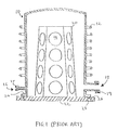
- YAMAGA discloses a glass process chamber 10, heated a number of heating elements12, and in which semiconductor substrates 14 are processed.
- Process and/or purge gas is introduced through a gas inlet 16, the process chamber 10 exhausted or evacuated through an exhaust port 18.
- the gas inlet 16 is sealed to a gas supply line (not shown) by an o-ring 17, and the exhaust port 18 is scaled by a gasket 19 to an exhaust trunk or vacuum pump foreline (not shown).
- the substrates 14 are held on a holder or support 20 mounted on a metal base plate 22 that can be raised or lowered by a lift mechanism (not shown) to load and remove the substrates.
- a lift mechanism not shown
- the base plate 22 is sealed to a flange 24 of the process chamber 10 by an o-ring 26.
- Water is passed through a coolant channel 28 in the base plate 22 below and adjacent to the o-ring 26 to cool the o-ring.
- the present invention preferably provides a solution to these and other problems, and may offer other advantages over the prior art.
- a process chamber for processing work pieces, such as semiconductor substrates, at high or elevated temperatures.
- the process chamber includes a wall having an aperture therein, a flange disposed about the aperture, and an insulator between the flange and a fixture to insulate a seal between the flange and the fixture.
- the insulator principally includes a tube or cooling loop having a sidewall overlying the flange and attached to the flange, and a cap overlying the cooling loop, the cap having a sealing surface against which the seal seats to seal the flange to the Fixture.
- fluid is passed through the cooling loop to reduce beat transferred to the seal from the process chamber during a processing operation.
- the flange, the cooling loop and the cap are made of a glass material or quartz.
- the sidewall of the cooling loop can be welded to the flange and the cap, or can be integrally formed therewith.
- the fixture is a door covering a doorway through which work pieces, such as semiconductor substrates, are loaded into the process chamber.
- the fixture can be a fitting or connection connecting the process chamber to a vacuum pump, an exhaust line, or a process or vent gas supply.
- the flange has a cylindrical shape open at a distal end distal from the process chamber, and the cooling loop has a curved substantially circular shape with a diameter substantially equal to that of the flange.
- the cooling loop itself can have an internal passage with either a circular or polygonal cross-sectional area, for example square.
- the cooling loop comprises a channel or groove machined into a portion of a surface of the flange, and the cap overlays the channel to form the internal passage through which the heat transfer fluid is passed to insulate the seal.
- the cooling loop is adapted to function as a light pipe to direct heat radiating from the process chamber away from the seal.
- Electromagnetic radiation or energy (light) is conducted through the material of the sidewall of the process chamber just as it does through an optical fiber in fiber optic communication.
- the presence of a discontinuity moving from one medium, such as quartz, to another medium such as a gas or fluid in the insulator results in reflection of some of the energy back towards a process zone, stabilizing and improving temperature control, and refraction away from the seal. The net effect is to greatly reduce the amount of electro-magnetic energy coupled to the vulnerable seal.
- the fluid passed through the cooling loop is a gas, to avoid stresses in the cooling loop, cap and flange resulting from drastic cooling near an inlet to the loop, differential cooling at different points along the cooling loop, or the impediment to heat transfer caused by vaporization of a liquid.
- the gas is selected from the group consisting of air, nitrogen, helium or argon.
- the gas passed through the cooling loop or tube is a process gas used in the process chamber during the processing operation, and the gas is introduced into the process chamber after having passed through the cooling loop, thereby preheating the process gas prior to introduction into the process chamber. This embodiment is particularly desirable for those processes in which it is necessary to maintain a specified temperature profile in the process chamber while providing a high flow of process gases, for example in a Chemical Vapor Deposition (CVD) system.
- CVD Chemical Vapor Deposition
- a method for insulating a seal between a process chamber and a fixture, the process chamber having a wall with an aperture therein, and a flange disposed about the aperture.
- the method involves: (i) attaching a cooling loop having a sidewall to the flange so that the sidewall overlies the flange; (ii) attaching a cap to the cooling loop, the cap having a sealing surface against which the seal seats to seal the flange to the fixture; and (iii) passing a fluid through the cooling loop to reduce heat transferred to the seal from the process chamber during a process operation.
- the step of attaching the cooling loop to the flange can be accomplished by welding the sidewall of the cooling loop to the flange.
- the flange includes a cylindrical shape open at a distal end distal from the process the chamber, and the step of attaching a cooling loop to the flange involves attaching a cooling loop curved substantially into a circle having a diameter substantially equal to the flange.
- the step of passing a fluid through the cooling loop includes the step of flowing a gas through the cooling loop.
- the gas is selected from the group consisting of air, nitrogen, helium or argon.
- the gas is a process gas used in the process chamber during the processing operation, and the step of flowing a gas through the cooling loop involves introducing the process gas into the process chamber after flowing it through the cooling loop, thereby preheating the process gas prior to use.
- an insulator is provided, as set out in claim 23.
- the present invention is directed to an apparatus and method for insulating and maintaining a seal in pressurized, evacuated or exhausted process chambers.
- FIG. 2 is a cross-sectional view of a heated process chamber 100 having a flange 115 to which the insulator 105 is attached to insulate the seal 110.
- the seal 110 generally seals the flange to a fixture, such as a door 120 shown in the exemplary embodiment
- a fixture such as a door 120 shown in the exemplary embodiment
- the process chamber 100 generally includes a wall or sidewall 125, an end wall 130, and the flange 115 disposed about or defining an aperture or opening 140, such as à doorway at one end of the sidewall through which work pieces, such as semiconductor substrates or wafers (not shown) can be loaded into the process chamber.
- Furnace or coaxial heating elements 145 surround or are disposed about the process chamber 100 to thermally treat or heat the work piece therein to an elevated temperature.
- the work pieces is heated to at 1100 °C (2012°F) and more preferably from about 1200 °C (2192°F) to about 1500 °C (2732°F)
- the process chamber 100 can consist of any material capable of withstanding the heat, pressure of an evacuated or pressurized process chamber, and chemicals used in processing the work pieces. Suitable materials for the process chamber 100 include, high temperature glass, ceramics, and clear or opaque quartz glass or quartz.
- the process chamber 100 is a long quartz cylinder closed at one end by the end wall 130 and at the outer end by a fixture such as a door 120, also made of quartz.
- This embodiment is particularly suitable for use with fumaces, such as Rapid Vertical Processors, Vertical Thermal Reactors, and Horizontal Thermal Reactors commercially available from ASML Inc., of La Veldhoven, The Netherlands, which are widely used in semiconductor manufacturing to, for example, anneal, diffuse or drive in dopant material, and to grow or deposit oxide or poly silicon layers on substrates.
- fumaces such as Rapid Vertical Processors, Vertical Thermal Reactors, and Horizontal Thermal Reactors commercially available from ASML Inc., of La Veldhoven, The Netherlands, which are widely used in semiconductor manufacturing to, for example, anneal, diffuse or drive in dopant material, and to grow or deposit oxide or poly silicon layers on substrates.
- the process chamber 100 includes one or more gas inlets 155 for introducing process and/or vent gases therein, and an exhaust port 160 for exhausting spent process gases and/or byproducts.
- the exhaust port 160 can be coupled to a vacuum pump (not shown) to evacuate the process chamber 100 for processes performed at a high or low vacuum.
- the process chamber 100 can further include one or more holders 165 for holding and positioning one or more substrates (not shown) within a process zone 170 in the process chamber.
- the process zone 170 is a region within the process chamber 100 in which temperature and the concentration of process gases is tightly controlled to facilitate the processing of the substrates.
- the process chamber 100 is supported within the furnace or the heating elements 145 by a clamp 175 including a front or face-piece 180 disposed about an outer circumference of the flange 115, and a backing ring or piece 185 having an internal diameter smaller than an outer diameter of the flange but larger than that of the sidewall 125 of the process chamber 100.
- the clamp 175 is attached by mechanical fasteners 190 to a front plate 195 or wall of the furnace or an enclosure containing the heating the elements 145.
- brackets 200 may be attached to the front plate 195 or the clamp 175 for mounting a mechanism (not shown) for automatically loading substrates and/or opening and closing the door 120.
- the door 120 includes a metal ring 210 disposed about and sealed by a gas tight seal to a central quartz plate or disc 215 that substantially covers the opening 140 into the process chamber 100.
- the surface of the metal ring 210 is treated or coated with a matezial to resist corrosion or reaction with the process gases or byproducts.
- the door 120 can be made entirely of quartz or metal.
- the metal ring 210 includes a groove 220 for holding a polymeric seal 110, such as an o-ring or a seal having a square cross-sectional area, for sealing with the flange 115 to provide a substantially gas tight seal.
- the door 120 further includes a cooling channel 235 through which a heat transfer fluid, such as water, is circulated to cool the seal 110.
- the material of the seal 110 is selected for its resilience and ability to provide a satisfactory seal, and for it ability to withstand the process gases or byproducts and the heat from the process chamber 100. Suitable materials include, for example, resilient polymeric material such as silicone, fluorosilicone, tetrafluoroethylene/Propylene or TFE/Propylene, fluorocarbon, polyacrylate, nitrite, hydrogenated nitrile, neoprene, ethylene propylene or butyl rubber.
- the seal 110 seals with an insulator 105 attached to the flange 115 to insulate and maintain a seal in a pressurized, evacuated or exhausted process chambers 100.
- the insulator 105 and the method described provide, inter alia, improved seal 110 integrity, and improved process stability and personnel safety due to improved seal integrity.
- the insulator 105 and method reduce potential for process chamber 100 contamination due to thermally degraded seal 110, and reduced operating costs and increased equipment availability due to extended seal lifetime.
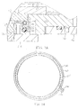
- FIG. 3A is a partial cross-sectional view of an insulator 105, flange 115 and a door 120 through which work pieces, such as semiconductor substrates, can be loaded into the process chamber 100.
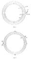
- FIG. 3B is a planar top view of the flange 115 and the insulator 105 of FIG. 2.
- the insulator 105 generally includes an annular cap 255 having a sealing surface 257 against which the seal 110 is pressed when the door 120 is in the closed position, and a cooling loop or tube 260 between the cap and the flange.
- the cooling tube 260 includes an inlet 265 (shown in FIG 3B), an outlet 270 (shown in FIG. 3B), and walls or sidewall 262 defining an internal passage 275 through which a heat transfer fluid is passed or flowed.
- the heat transfer fluid cools the seal 110 and/or insulates it from heat transferred from the process chamber 100 to reduce or substantially eliminate thermal degradation of the seal.
- the cooling tube 260 and cap 255 are made of glass or quartz and the cooling loop is fused or welded to the flange 115 and to the cap with quartz to form a substantially gas tight structure.
- the reduced surface area of the cooling tube 260 in contact with the flange 115 and the cap 255 serves a thermal barrier to reduce conduction of heat from the process chamber 100 to the teal 110.
- the flange 115, the cooling tube 260, the cap 255 and/or a portion of the sidewall 125 of the process chamber 100 can be made from opaque quartz to further reduce the transfer of heat from the process chamber 100 to the seal 110.
- Opaque quartz is quartz in which microscopic air bubbles have been introduced during the manufacturing process before the quartz has solidified. These microscopic air bubbles reduce the rate at which heat is conducted through the opaque quartz and the rate at which heat is radiated from the process chamber 100 to the seal 110.
- electro-magnetic radiation or energy (light) can travel through the material of the sidewall 125 of the process chamber 100 just as it does through an optical fiber in fiber optic communication.
- the heat transfer fluid can include a gas, such as air, nitrogen, helium or argon, or a liquid such water.
- a gas such as air, nitrogen, helium or argon
- a liquid such water.
- the heat transfer fluid is a gas. More preferably, the rate at which the gas flows through the cooling loop 260 is selected based on the operating temperature of the process chamber 100, the size of the cooling loop and the size of the seal 110, to maintain the seal at or below its maximum rated temperature for a predetermined process time.
- a cooling loop 260 having a diameter or circumference of about 41 cm (16 inches) made from tubing having an inner diameter of at least 2.5 mm (0.0975 inches) and having a gas flow through the cooling loop 260 of from about 2 to about 200 liters per minute (LPM), and more preferably of from about 20 LPM at from about 30 pounds per square inch (PSI) to 60 PSI.
- LPM liters per minute
- the gas flowed through the cooling loop 260 is a process or vent gas that is flowed through the cooling loop before being introduced into the process chamber 100.
- This embodiment has the advantage of cooling and insulating the seal 110 while simultaneously preheating the gas thereby helping the heating elements 145 to maintain a stable, elevated temperature in the process zone 170.
- the cooling loop 260 is sized, shaped and made from a material selected to enable the cooling loop to function as a light pipe to direct heat radiating from the piocess chamber 100 away from the seal 110.
- electro-magnetic radiation or energy (light) can travel through the material of the sidewall 125 of the process chamber 100 just as it does through an optical fiber in fiber optic communication.
- the presence of a discontinuity moving from one medium, such as quartz, to another medium such as a gas or fluid in the cooling loop 260 results in refraction and reflection of some of the energy. That is, some of the energy is reflected back to the process zone 170, and some is refracted away from its original direction of travel and away from the seal 110.
- the net effect is to greatly reduce the amount of electro-magnetic energy coupled to the vulnerable seal 110.
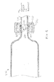
- FIG. 4 is a partial cross-sectional view of an exhaust port 285 in a process chamber 290 having a flange 295 to which an insulator 280 according to an embodiment of the present invention is attached.
- the insulator 280 generally includes a quartz cooling tube or loop 300 welded to and between the flange 295 disposed about or defining an opening 305 in the process chamber 290, and an annular cap 310 having a sealing surface 315 against which a seal 320 is pressed when the flange 295 is coupled to a fixture 325 such as a foreline of a vacnum pump or an exhaust trunk (not shown).
- the flange 295 is coupled to the fixture 325 by, for example, a clamp 330.
- the fixture 325 can include a cooling channel (not shown) near the seal 320, and through which water is passed to cool the seal further.
- a smaller version of an insulator according to an embodiment of the present invention can be used to insulate a seal in a gas inlet to a process chamber (not shown). It will be appreciated that this embodiment is particularly suited for using a process gas or vent gas as the heat transfer fluid.
- the cooling tube 260 of the insulator 105 has a square cross-sectional area
- This embodiment has the advantages of providing a larger area of a sidewall 335 of the cooling tube in contact with the flange 115, thereby increasing the strength of the welded joint 340 between the insulator 105 and the flange 115.
- the cap 255 or sealing surface 257 can be integrally formed with the cooling loop 260 by providing a substantially flat planar surface on an outside surface of the cooling loop facing away from the flange 115, arid against which the seal 110 will seat.
- this embodiment has the further advantage of reducing manufacturing time and costs by eliminating a part, the cap 255, and one or more steps, i.e., the steps of manufacturing the cap and attaching it to the cooling loop 260.
- the cooling tube 260 of the insulator 105 is integrally formed in the flange 115.
- the cooling tube 260 comprises a channel 350 or groove machined into part of a surface 355 of the flange 115, and the cap 255 overlaying the channel to form the internal passage 275 through which the heat transfer fluid is passed.
- This embodiment has the advantage of eliminating the weld between the cooling loop 260 and the flange 115 thereby eliminating a potential source of leaks.
- the insulator 105 can include multiple cooling tubes 260 to further cool and insulate the seal 110.
- the insulator 105 includes multiple stacked cooling tubes 260a, 260b, between the flange 115 and the cap 255.
- FIG. 8 illustrates an insulator 105 having multiple concentric cooling tubes 260a, 260b, between the flange 115 and the cap 255
- the insulator 105 can include segmented cooling tubes 260, wherein each segment cools and insulates a portion of the seal.
- the cooling tube 260 is divided into four segments each of which cool and insulate a quarter of the total circumference or diameter of the seal 110.
- FIG. 10 is a flow chart showing steps of a method for insulating a seal 110 between a process chamber 100 and a fixture.
- the method involves: (i) attaching a cooling tube or loop 260 having a sidewall 262 to the flange 115 so that the sidewall overlies the flange (step 400); (ii) attaching a cap 255 to the cooling loop 260, the cap having a sealing surface 257 against which the seal 110 seats to seal the flange 115 to the fixture (step 405); and (iii) passing a fluid through the cooling loop 260 to reduce heat transferred to the seal 110 from the process chamber 100 during a process operation (step 410).
- the step of attaching the cooling loop 260 to the flange 115 can be accomplished by welding the sidewall 262 of the cooling loop to the flange.
- the flange 115 includes a cylindrical shape open at a distal end distal from the process chamber 100, and the step of attaching a cooling loop 260 to the flange, step 400, involves attaching a cooling loop curved substantially into a circle having a diameter substantially equal to that of the flange.
- the step of passing a fluid through the cooling loop 260, step 410 includes the step of flowing a gas through the cooling loop.
- the gas is selected from the group consisting of air, nitrogen, helium or argon.
- the gas is a process gas used in the process chamber 100 during the processing operation, and the method further includes the step of introducing the process gas into the process chamber (step 415) after flowing it through the cooling loop 260, step 410, thereby preheating the process gas prior to use.
- the first example, illustrated by graph 420, demonstrates the ability of an insulator 105 according to an embodiment of the present invention to insulate a seal 110 solely by light piping and the thermal barrier effect without fluid flow through the cooling tube 260.
- the inlet 265 and outlet 270 to the cooling tube 260 were left open to atmosphere, and water was passed through the cooling channel 235 in the door 120 at a rate of two and half gallons per minute (GPM).
- Thermocouples or TCs were positioned radially spaced apart about the o-ring seal 110.
- the process chamber 100 reached a temperature of 500 °C in the process zone 170 resulting in a maximum o-ring temperature of about 250 °C, as shown in FIG 11 by reference number 425, well below the rated maximum temperature of most types of o-rings used in this application.
- the heater set point was increased to 900 °C resulting in a maximum o-ring temperature of about 285C after about half an hour of heating, as indicated by reference number 430.
- a second example, illustrated by graph 435, demonstrates the ability of an insulator 105 according to an embodiment of the present invention to insulate a seal 110 when a fluid is flowing through the cooling loop 260.
- nitrogen (N 2 ) at a rate of 160 cubic feet per hour (Cfh) was passed through the cooling loop 260, and water was passed through the cooling channel 235 in the door at a rate of two and half gallons per minute (GPM).
- GPM gallons per minute
Landscapes
- Chemical & Material Sciences (AREA)
- General Chemical & Material Sciences (AREA)
- Chemical Kinetics & Catalysis (AREA)
- Engineering & Computer Science (AREA)
- Materials Engineering (AREA)
- Mechanical Engineering (AREA)
- Metallurgy (AREA)
- Organic Chemistry (AREA)
- Chemical Vapour Deposition (AREA)
- Physical Or Chemical Processes And Apparatus (AREA)
Applications Claiming Priority (2)
| Application Number | Priority Date | Filing Date | Title |
|---|---|---|---|
| US31371901P | 2001-08-20 | 2001-08-20 | |
| US313719P | 2001-08-20 |
Publications (2)
| Publication Number | Publication Date |
|---|---|
| EP1285977A2 true EP1285977A2 (de) | 2003-02-26 |
| EP1285977A3 EP1285977A3 (de) | 2004-06-30 |
Family
ID=23216843
Family Applications (1)
| Application Number | Title | Priority Date | Filing Date |
|---|---|---|---|
| EP02255775A Withdrawn EP1285977A3 (de) | 2001-08-20 | 2002-08-20 | Vorrichtung und Verfahren zum Isolieren einer Dichtung in einer Prozesskammer |
Country Status (7)
| Country | Link |
|---|---|
| US (1) | US20030116280A1 (de) |
| EP (1) | EP1285977A3 (de) |
| JP (1) | JP2003178991A (de) |
| KR (1) | KR20030016188A (de) |
| CN (1) | CN1405863A (de) |
| SG (1) | SG116461A1 (de) |
| TW (1) | TW564498B (de) |
Cited By (1)
| Publication number | Priority date | Publication date | Assignee | Title |
|---|---|---|---|---|
| CN114551206A (zh) * | 2015-12-04 | 2022-05-27 | 应用材料公司 | 用以防止hdp-cvd腔室电弧放电的先进涂层方法及材料 |
Families Citing this family (8)
| Publication number | Priority date | Publication date | Assignee | Title |
|---|---|---|---|---|
| US8648977B2 (en) | 2004-06-02 | 2014-02-11 | Applied Materials, Inc. | Methods and apparatus for providing a floating seal having an isolated sealing surface for chamber doors |
| US8206075B2 (en) | 2004-06-02 | 2012-06-26 | Applied Materials, Inc. | Methods and apparatus for sealing a chamber |
| CN100552223C (zh) * | 2005-09-09 | 2009-10-21 | 联华电子股份有限公司 | 泵环 |
| JP4705905B2 (ja) * | 2006-12-19 | 2011-06-22 | 日本発條株式会社 | 熱処理装置用冷却装置及びその製造方法 |
| CN101881335B (zh) * | 2010-03-23 | 2012-02-01 | 东莞宏威数码机械有限公司 | 多层橡胶密封圈密封装置 |
| KR20140078284A (ko) * | 2012-12-17 | 2014-06-25 | 삼성디스플레이 주식회사 | 증착원 및 이를 포함하는 증착 장치 |
| CN112103205B (zh) * | 2019-06-17 | 2024-05-17 | 北京北方华创微电子装备有限公司 | 排气装置及工艺腔室 |
| JP7411699B2 (ja) * | 2022-01-28 | 2024-01-11 | 株式会社Kokusai Electric | 基板処理装置及び半導体装置の製造方法 |
Family Cites Families (17)
| Publication number | Priority date | Publication date | Assignee | Title |
|---|---|---|---|---|
| JPS56124437A (en) * | 1980-03-07 | 1981-09-30 | Chiyou Lsi Gijutsu Kenkyu Kumiai | Gas phase chemical reaction apparatus |
| US4545327A (en) * | 1982-08-27 | 1985-10-08 | Anicon, Inc. | Chemical vapor deposition apparatus |
| US4547404A (en) * | 1982-08-27 | 1985-10-15 | Anicon, Inc. | Chemical vapor deposition process |
| KR0171600B1 (ko) * | 1990-02-26 | 1999-03-30 | 이노우에 아끼라 | 밀봉장치 |
| US5318633A (en) * | 1991-03-07 | 1994-06-07 | Tokyo Electron Sagami Limited | Heat treating apparatus |
| US5320680A (en) * | 1991-04-25 | 1994-06-14 | Silicon Valley Group, Inc. | Primary flow CVD apparatus comprising gas preheater and means for substantially eddy-free gas flow |
| JPH05287521A (ja) * | 1992-04-09 | 1993-11-02 | Tel Varian Ltd | スパッタ装置 |
| US5540782A (en) * | 1992-10-15 | 1996-07-30 | Tokyo Electron Kabushiki Kaisha | Heat treating apparatus having heat transmission-preventing plates |
| US5578132A (en) * | 1993-07-07 | 1996-11-26 | Tokyo Electron Kabushiki Kaisha | Apparatus for heat treating semiconductors at normal pressure and low pressure |
| US6171982B1 (en) * | 1997-12-26 | 2001-01-09 | Canon Kabushiki Kaisha | Method and apparatus for heat-treating an SOI substrate and method of preparing an SOI substrate by using the same |
| TW430866B (en) * | 1998-11-26 | 2001-04-21 | Tokyo Electron Ltd | Thermal treatment apparatus |
| KR100345053B1 (ko) * | 1999-10-01 | 2002-07-19 | 삼성전자 주식회사 | Hsg-si 제조 방법 및 상기 방법을 수행하는 장치 |
| KR20010045802A (ko) * | 1999-11-08 | 2001-06-05 | 윤종용 | 저압 화학 기상 증착용 수평로의 플랜지 밀봉 장치 |
| KR20010046221A (ko) * | 1999-11-11 | 2001-06-05 | 윤종용 | 저압 화학 기상 증착용 수평로의 플랜지 냉각 장치 |
| KR100640564B1 (ko) * | 2000-01-17 | 2006-10-31 | 삼성전자주식회사 | 가스 분사 장치를 포함하는 반도체 소자 제조 장비 |
| KR100336524B1 (ko) * | 2000-08-07 | 2002-05-11 | 윤종용 | 반도체 제조용 화학기상증착 장치의 뷰우포트 |
| TWI334888B (de) * | 2000-09-08 | 2010-12-21 | Tokyo Electron Ltd |
-
2002
- 2002-08-19 TW TW091118697A patent/TW564498B/zh not_active IP Right Cessation
- 2002-08-19 CN CN02143456A patent/CN1405863A/zh active Pending
- 2002-08-20 US US10/224,687 patent/US20030116280A1/en not_active Abandoned
- 2002-08-20 EP EP02255775A patent/EP1285977A3/de not_active Withdrawn
- 2002-08-20 JP JP2002280066A patent/JP2003178991A/ja active Pending
- 2002-08-20 SG SG200205046A patent/SG116461A1/en unknown
- 2002-08-20 KR KR1020020049154A patent/KR20030016188A/ko not_active Abandoned
Cited By (1)
| Publication number | Priority date | Publication date | Assignee | Title |
|---|---|---|---|---|
| CN114551206A (zh) * | 2015-12-04 | 2022-05-27 | 应用材料公司 | 用以防止hdp-cvd腔室电弧放电的先进涂层方法及材料 |
Also Published As
| Publication number | Publication date |
|---|---|
| TW564498B (en) | 2003-12-01 |
| EP1285977A3 (de) | 2004-06-30 |
| JP2003178991A (ja) | 2003-06-27 |
| SG116461A1 (en) | 2005-11-28 |
| CN1405863A (zh) | 2003-03-26 |
| US20030116280A1 (en) | 2003-06-26 |
| KR20030016188A (ko) | 2003-02-26 |
Similar Documents
| Publication | Publication Date | Title |
|---|---|---|
| US11784076B2 (en) | Substrate transfer mechanism to reduce back-side substrate contact | |
| KR880000472B1 (ko) | 화학 증착 장치 및 방법 | |
| US5368648A (en) | Sealing apparatus | |
| US6187102B1 (en) | Thermal treatment apparatus | |
| US20050098107A1 (en) | Thermal processing system with cross-flow liner | |
| US6283175B1 (en) | Enveloping device and vertical heat-treating apparatus for semiconductor process system | |
| KR100280692B1 (ko) | 열처리장치 및 열처리방법 | |
| US20040060519A1 (en) | Quartz to quartz seal using expanded PTFE gasket material | |
| US5370371A (en) | Heat treatment apparatus | |
| US5884917A (en) | Thermal processing apparatus | |
| KR100380213B1 (ko) | 반도체 처리 시스템 및 기판 처리 장치 | |
| JP4200844B2 (ja) | 熱処理装置 | |
| EP1285977A2 (de) | Vorrichtung und Verfahren zum Isolieren einer Dichtung in einer Prozesskammer | |
| US6844527B2 (en) | Multi-thermal zone shielding apparatus | |
| JP4963336B2 (ja) | 熱処理装置 | |
| US4547404A (en) | Chemical vapor deposition process | |
| US5497727A (en) | Cooling element for a semiconductor fabrication chamber | |
| EP1463093A2 (de) | Vorrichtung zur thermischen Behandlung von Halbleitern | |
| KR20010056330A (ko) | 반도체소자 제조장치 | |
| JPH0982656A (ja) | 縦型熱処理装置 | |
| JP3256037B2 (ja) | 熱処理装置 | |
| US20230290614A1 (en) | Heat shield assemblies for minimizing heat radiation to pump of process chamber | |
| JP4364962B2 (ja) | 基板処理装置及び基板処理方法 | |
| KR102879243B1 (ko) | 기판 처리 장치 | |
| JPH03272365A (ja) | 封止装置 |
Legal Events
| Date | Code | Title | Description |
|---|---|---|---|
| PUAI | Public reference made under article 153(3) epc to a published international application that has entered the european phase |
Free format text: ORIGINAL CODE: 0009012 |
|
| AK | Designated contracting states |
Kind code of ref document: A2 Designated state(s): AT BE BG CH CY CZ DE DK EE ES FI FR GB GR IE IT LI LU MC NL PT SE SK TR Designated state(s): AT BE BG CH CY CZ DE DK EE ES FI FR GB GR IE IT LI LU MC NL PT SE SK TR |
|
| AX | Request for extension of the european patent |
Extension state: AL LT LV MK RO SI |
|
| PUAL | Search report despatched |
Free format text: ORIGINAL CODE: 0009013 |
|
| RIC1 | Information provided on ipc code assigned before grant |
Ipc: 7F 16J 15/00 B Ipc: 7H 01L 21/00 B Ipc: 7C 23C 16/44 B Ipc: 7B 65D 43/00 B Ipc: 7F 16J 13/00 A |
|
| AK | Designated contracting states |
Kind code of ref document: A3 Designated state(s): AT BE BG CH CY CZ DE DK EE ES FI FR GB GR IE IT LI LU MC NL PT SE SK TR |
|
| AX | Request for extension of the european patent |
Extension state: AL LT LV MK RO SI |
|
| AKX | Designation fees paid |
Designated state(s): DE FR GB IT NL |
|
| STAA | Information on the status of an ep patent application or granted ep patent |
Free format text: STATUS: THE APPLICATION IS DEEMED TO BE WITHDRAWN |
|
| 18D | Application deemed to be withdrawn |
Effective date: 20050104 |