EP1285976B1 - CVI/CVD Verfahren - Google Patents
CVI/CVD Verfahren Download PDFInfo
- Publication number
- EP1285976B1 EP1285976B1 EP02017264A EP02017264A EP1285976B1 EP 1285976 B1 EP1285976 B1 EP 1285976B1 EP 02017264 A EP02017264 A EP 02017264A EP 02017264 A EP02017264 A EP 02017264A EP 1285976 B1 EP1285976 B1 EP 1285976B1
- Authority
- EP
- European Patent Office
- Prior art keywords
- reactant gas
- center opening
- opening region
- region
- outer region
- Prior art date
- Legal status (The legal status is an assumption and is not a legal conclusion. Google has not performed a legal analysis and makes no representation as to the accuracy of the status listed.)
- Expired - Lifetime
Links
Images


Classifications
-
- C—CHEMISTRY; METALLURGY
- C23—COATING METALLIC MATERIAL; COATING MATERIAL WITH METALLIC MATERIAL; CHEMICAL SURFACE TREATMENT; DIFFUSION TREATMENT OF METALLIC MATERIAL; COATING BY VACUUM EVAPORATION, BY SPUTTERING, BY ION IMPLANTATION OR BY CHEMICAL VAPOUR DEPOSITION, IN GENERAL; INHIBITING CORROSION OF METALLIC MATERIAL OR INCRUSTATION IN GENERAL
- C23C—COATING METALLIC MATERIAL; COATING MATERIAL WITH METALLIC MATERIAL; SURFACE TREATMENT OF METALLIC MATERIAL BY DIFFUSION INTO THE SURFACE, BY CHEMICAL CONVERSION OR SUBSTITUTION; COATING BY VACUUM EVAPORATION, BY SPUTTERING, BY ION IMPLANTATION OR BY CHEMICAL VAPOUR DEPOSITION, IN GENERAL
- C23C16/00—Chemical coating by decomposition of gaseous compounds, without leaving reaction products of surface material in the coating, i.e. chemical vapour deposition [CVD] processes
- C23C16/44—Chemical coating by decomposition of gaseous compounds, without leaving reaction products of surface material in the coating, i.e. chemical vapour deposition [CVD] processes characterised by the method of coating
- C23C16/458—Chemical coating by decomposition of gaseous compounds, without leaving reaction products of surface material in the coating, i.e. chemical vapour deposition [CVD] processes characterised by the method of coating characterised by the method used for supporting substrates in the reaction chamber
-
- C—CHEMISTRY; METALLURGY
- C23—COATING METALLIC MATERIAL; COATING MATERIAL WITH METALLIC MATERIAL; CHEMICAL SURFACE TREATMENT; DIFFUSION TREATMENT OF METALLIC MATERIAL; COATING BY VACUUM EVAPORATION, BY SPUTTERING, BY ION IMPLANTATION OR BY CHEMICAL VAPOUR DEPOSITION, IN GENERAL; INHIBITING CORROSION OF METALLIC MATERIAL OR INCRUSTATION IN GENERAL
- C23C—COATING METALLIC MATERIAL; COATING MATERIAL WITH METALLIC MATERIAL; SURFACE TREATMENT OF METALLIC MATERIAL BY DIFFUSION INTO THE SURFACE, BY CHEMICAL CONVERSION OR SUBSTITUTION; COATING BY VACUUM EVAPORATION, BY SPUTTERING, BY ION IMPLANTATION OR BY CHEMICAL VAPOUR DEPOSITION, IN GENERAL
- C23C16/00—Chemical coating by decomposition of gaseous compounds, without leaving reaction products of surface material in the coating, i.e. chemical vapour deposition [CVD] processes
- C23C16/04—Coating on selected surface areas, e.g. using masks
- C23C16/045—Coating cavities or hollow spaces, e.g. interior of tubes; Infiltration of porous substrates
-
- C—CHEMISTRY; METALLURGY
- C23—COATING METALLIC MATERIAL; COATING MATERIAL WITH METALLIC MATERIAL; CHEMICAL SURFACE TREATMENT; DIFFUSION TREATMENT OF METALLIC MATERIAL; COATING BY VACUUM EVAPORATION, BY SPUTTERING, BY ION IMPLANTATION OR BY CHEMICAL VAPOUR DEPOSITION, IN GENERAL; INHIBITING CORROSION OF METALLIC MATERIAL OR INCRUSTATION IN GENERAL
- C23C—COATING METALLIC MATERIAL; COATING MATERIAL WITH METALLIC MATERIAL; SURFACE TREATMENT OF METALLIC MATERIAL BY DIFFUSION INTO THE SURFACE, BY CHEMICAL CONVERSION OR SUBSTITUTION; COATING BY VACUUM EVAPORATION, BY SPUTTERING, BY ION IMPLANTATION OR BY CHEMICAL VAPOUR DEPOSITION, IN GENERAL
- C23C16/00—Chemical coating by decomposition of gaseous compounds, without leaving reaction products of surface material in the coating, i.e. chemical vapour deposition [CVD] processes
- C23C16/22—Chemical coating by decomposition of gaseous compounds, without leaving reaction products of surface material in the coating, i.e. chemical vapour deposition [CVD] processes characterised by the deposition of inorganic material, other than metallic material
- C23C16/26—Deposition of carbon only
-
- C—CHEMISTRY; METALLURGY
- C23—COATING METALLIC MATERIAL; COATING MATERIAL WITH METALLIC MATERIAL; CHEMICAL SURFACE TREATMENT; DIFFUSION TREATMENT OF METALLIC MATERIAL; COATING BY VACUUM EVAPORATION, BY SPUTTERING, BY ION IMPLANTATION OR BY CHEMICAL VAPOUR DEPOSITION, IN GENERAL; INHIBITING CORROSION OF METALLIC MATERIAL OR INCRUSTATION IN GENERAL
- C23C—COATING METALLIC MATERIAL; COATING MATERIAL WITH METALLIC MATERIAL; SURFACE TREATMENT OF METALLIC MATERIAL BY DIFFUSION INTO THE SURFACE, BY CHEMICAL CONVERSION OR SUBSTITUTION; COATING BY VACUUM EVAPORATION, BY SPUTTERING, BY ION IMPLANTATION OR BY CHEMICAL VAPOUR DEPOSITION, IN GENERAL
- C23C16/00—Chemical coating by decomposition of gaseous compounds, without leaving reaction products of surface material in the coating, i.e. chemical vapour deposition [CVD] processes
- C23C16/44—Chemical coating by decomposition of gaseous compounds, without leaving reaction products of surface material in the coating, i.e. chemical vapour deposition [CVD] processes characterised by the method of coating
- C23C16/455—Chemical coating by decomposition of gaseous compounds, without leaving reaction products of surface material in the coating, i.e. chemical vapour deposition [CVD] processes characterised by the method of coating characterised by the method used for introducing gases into reaction chamber or for modifying gas flows in reaction chamber
-
- Y—GENERAL TAGGING OF NEW TECHNOLOGICAL DEVELOPMENTS; GENERAL TAGGING OF CROSS-SECTIONAL TECHNOLOGIES SPANNING OVER SEVERAL SECTIONS OF THE IPC; TECHNICAL SUBJECTS COVERED BY FORMER USPC CROSS-REFERENCE ART COLLECTIONS [XRACs] AND DIGESTS
- Y10—TECHNICAL SUBJECTS COVERED BY FORMER USPC
- Y10S—TECHNICAL SUBJECTS COVERED BY FORMER USPC CROSS-REFERENCE ART COLLECTIONS [XRACs] AND DIGESTS
- Y10S427/00—Coating processes
- Y10S427/10—Chemical vapor infiltration, i.e. CVI
-
- Y—GENERAL TAGGING OF NEW TECHNOLOGICAL DEVELOPMENTS; GENERAL TAGGING OF CROSS-SECTIONAL TECHNOLOGIES SPANNING OVER SEVERAL SECTIONS OF THE IPC; TECHNICAL SUBJECTS COVERED BY FORMER USPC CROSS-REFERENCE ART COLLECTIONS [XRACs] AND DIGESTS
- Y10—TECHNICAL SUBJECTS COVERED BY FORMER USPC
- Y10T—TECHNICAL SUBJECTS COVERED BY FORMER US CLASSIFICATION
- Y10T428/00—Stock material or miscellaneous articles
- Y10T428/29—Coated or structually defined flake, particle, cell, strand, strand portion, rod, filament, macroscopic fiber or mass thereof
- Y10T428/2902—Channel shape
Definitions
- the present invention relates generally to chemical vapor infiltration and deposition ("CVI/CVD”) processes, and more particularly, to a hardware assembly for supporting porous structures during a CVI/CVD process.
- CVI/CVD chemical vapor infiltration and deposition
- CVI/CVD Chemical vapor infiltration and deposition
- manufacturing carbon parts using a CVI/CVD process involves placing preformed porous structures in a furnace and introducing a high temperature reactant gas to the porous structures.
- porous structures and reactant gases may be used, but typically, a fibrous carbon porous structure is used with a reactant gas mixture of natural gas and/or propane gas when carbon/carbon aircraft brake disks are manufactured.
- a fibrous carbon porous structure is used with a reactant gas mixture of natural gas and/or propane gas when carbon/carbon aircraft brake disks are manufactured.
- the hydrocarbon gas mixture flows around and through the porous structures, some of the carbon atoms separate from the hydrocarbon molecules, thereby depositing the carbon atoms within the interior and onto the surface of the porous structures.
- the porous structures become more dense over time as more and more of the carbon atoms are deposited onto the structures.
- Densification processes for annular brake disks may be characterized as either conventional densification processes or rapid densification processes or variants thereof.
- annular brake disks are arranged in stacks with adjacent brake disks stacked on top of each other. A center opening region is thus formed through the center of each stack.
- spacers are placed between adjacent brake disks to form open passages between the center opening region and the outer region.
- the reactant gas flows randomly around the stack and may flow through the open passages from the center opening region to the outer region or vice versa.
- the pressure differential between the inlet and outlet ducts of the furnace is usually relatively low in conventional processes.
- soot and tar accumulations on surfaces of the brake disks and/or on the furnace equipment Another problem that often occurs during densification is soot and tar accumulations on surfaces of the brake disks and/or on the furnace equipment.
- soot usually refers to undesirable accumulations of carbon particles on the furnace equipment
- tar usually refers to undesirable accumulations of large hydrocarbon molecules on the brake disks and the furnace equipment.
- accumulations of soot and tar form when the reactant gas stagnates for a period of time in an area or comes into contact with cooler furnace surfaces. Stagnation typically occurs in areas where the gas flow is blocked or where the gas flow is moving more slowly than the surrounding gas flow. Sudden temperature changes also contribute to the formation of oily substances, such as tar.
- Seal-coating is one typical problem that can result from soot and tar accumulations, although seal-coating can also be caused by other conditions that are described below. Seal-coating can occur when soot and tar accumulates early in the densification process on surfaces of the porous structure. As the carbon and large hydrocarbon molecules accumulate on the surfaces of the porous structure, the surface pores eventually become blocked, or sealed, thus preventing the flow of reactant gas from further permeating the porous structure. As a result, densification of the interior region around the seal-coated surface prematurely stops, thereby leaving interior porous defects in the finished carbon part.
- the vacuum lines are used to generate the desired gas flow through the furnace.
- soot and tar accumulations sometimes build up in these lines and reduce the performance of the vacuum. Therefore, the vacuum lines must be regularly cleaned, which is a time consuming and expensive task.
- Residence time typically refers to the amount of time required for a gas to travel through the furnace or other designated area.
- a low residence time is associated with an unobstructed flow path and is generally preferred.
- seal-coating is a common problem that causes porous defects within the interior region of the completed carbon parts.
- seal-coating also can occur due to nonuniform carbon deposition. This typically occurs when a nonuniform gas flow accelerates carbon deposition at the surface of a part, thereby sealing the surface with carbon deposits and blocking gas diffusion into the interior of the carbon structure.
- this type of seal-coating occurs later in the densification process when the density of the porous structures are higher.
- Another problem associated with nonuniform carbon deposition is the formation of undesirable carbon microstructures.
- a rough laminar carbon microstructure is preferred because of the friction and thermal characteristics of this microstructure.
- smooth laminar and dark laminar carbon microstructures may form instead.
- smooth and dark laminar microstructures are generally undesirable because brake disk performance is reduced unless the outer surfaces containing the undesirable microstructures are machined off in subsequent operations.
- the present invention provides a method of chemical vapor infiltration and deposition as defined in claim 1.
- the dependent claims are related to individual embodiments of the invention.
- a hardware assembly for controlling the flow of gas through and around a stack of annular porous structures in a furnace during CVI/CVD processes.
- a distributor is provided which separates the gas into a first portion and a second portion.
- the first portion of gas passes to a center opening region formed by the stack of annular porous structures.
- the second portion of gas passes to the outer region around the stack of annular porous structures.
- Most of the first portion of gas is blocked from completely passing out the top end of the center opening region by a plate and a cap.
- Some of the first portion of gas is allowed to pass out the top end of the center opening region through holes in the cap and through an open passage between the top annular porous structure and the plate.
- the first portion passes to the center opening region and the second portion passes to the outer region without the use of a separate distributor.
- an open space is provided between a floor plate and a bottom base plate. Most of the gas flows from the open space as a second portion to the outer region, while some of the gas flows from the open space as a first portion to the center opening region. Most of the second portion flows through open passages between adjacent porous structures thereby commingling with the first portion. The commingled first and second portions pass out of the center opening region through an exit hole adjacent one end of the stack of porous structures.
- a hardware assembly 32 with gas distributors 24 is provided for chemical vapor infiltration and deposition ("CVI/CVD") processes.
- the hardware assembly 32 is especially useful for carbon densification of annular porous structures 2 used for high performance brake disks 2 but is likely to be useful in many other applications for composite structures as well.
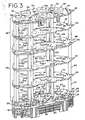
- the hardware assembly 32 supports and positions a number of brake disks 2 which are stacked on top of each other in a number of stacks 4.
- the hardware assembly 32 and stacks 4 of disks 2 are enclosed in a furnace 10 and hot hydrocarbon gases flow around and through the stacks 4 of brake disks 2, thereby depositing a carbon matrix within the interior regions and on the surface of the porous brake disk structures 2.
- a variety of processing parameters may be used to densify the porous structures 2, but an absolute gas pressure for the furnace 10 between 133 N/m 2 and 2666 N/m 2 (between 1 torr and 20 torr), a temperature range between 927°C and 1066°C (between 1,700° F and 1,950° F), and a densification time between 150 hours and 500 hours is especially suited for manufacturing aircraft brake disks 2.
- a variety of gas mixtures may also be used, but a gas mixture of 87% natural gas and 13% propane or a range of 80% to 100% natural gas and 20% to 0% propane is especially suited for manufacturing aircraft brake disks.
- furnaces 10 may be used for CVI/CVD processes.
- an induction furnace 10 is used that includes furnace walls 12 that enclose the hardware assembly 32 and the stacks 4 of brake disks 2.
- the furnace 10 also includes inlet ducts 14 and outlet ducts 16 for introducing and exhausting the gas mixture into and out of the furnace 10.
- a preheater 18 is also commonly provided within the furnace 10 to heat the gas before the gas is directed to the porous structures 2.
- the preheater 18 is sealed and the incoming gas from the inlet ducts 14 is received by the preheater 18 before being introduced to the hardware assembly 32.
- the preheated gas is then discharged from the preheater 18 through discharge openings 20 in the furnace floor plate 22 of the preheater 18.
- At least one distributor 24 is provided at the preheater discharge openings 20 for controlling the flow of gas around the stacks 4 of brake disks 2.
- the distributors 24 are removably mounted between the floor plate 22 of the preheater 18 and the base plate 46 of the bottom hardware assembly modules 34.
- recessed areas 19, 45 with guide diameters 21, 47 are provided in both the top surface of the floor plate 22 and the bottom surface of the hardware assembly base plate 46.
- the recessed areas 19 in the floor plate 22 are generally concentric with each of the discharge openings 20, and the recessed areas 45 in the hardware assembly base plate 46 are generally concentric with each of the inlet openings 53. Therefore, the distributors 24 may be easily installed by inserting the outer diameter 26 of each distributor 24 into one of the guide diameters 21 in the floor plate 22 and one of the guide diameters 47 in the base plate 46.
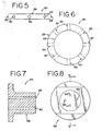
- the distributor 24 (also shown in Figures 5 and 6 ) divides the gas from the preheater 18 into at least two different portions and directs the portions in different directions. Accordingly, the distributor 24 includes an axial hole 28 that extends longitudinally through the distributor 24. Thus, a first portion of gas flows through the axial hole 28 from the preheater discharge opening 20 to the hardware assembly inlet opening 53.
- the distributor 24 also includes a number of radial holes 30 that extend out from the axial hole 28 to the outer diameter 26 of the distributor 24. Thus, a second portion of gas flows out of the distributor 24 through the radial holes 30 to the space between the floor plate 22 and the bottom base plate 46.
- the first portion that flows through the inlet opening 53 of the bottom base plate 46 represents about 76% of the gas mixture
- the second portion that flows out through the radial holes 30 represents about 24% of the gas mixture.
- the first gas flow portion is restricted by the inlet opening 53, which is about 12,70 cm (about 5 inches) in diameter, in the bottom base plate 46.
- the second gas flow portion is then restricted by the radial holes 30, which consist of eight holes about 2,54 cm (about 1 inch) in diameter.
- proportions for the first portion and second portion may also be advantageous, and other sizes and placement of the inlet opening 53, axial hole 28 and radial holes 30 may be used.
- the range of flow through the inlet opening may be as low as 20% to as much as 80%, while the range of flow into the space between the floor plate 22 and the bottom base plate 46 may be as high as 80% to as low as 20%.
- the preferred embodiment uses a proportion of about 80% for the first portion and about 20% for the second portion, but proportions between 70% and 90% for the first portion and 30% to 10% for the second portion and between 60% to 80% for the first portion and 40% to 20% for the second portion, or vice versa, may be used.
- a typical hardware assembly 32 preferably consists of a number of separate modules 34, 36 to make assembly, disassembly, loading and unloading of the hardware assembly 32 easier.
- the hardware assembly 32 includes a bottom set of modules 34 with three units 38.
- a unit 38 usually refers to the area between an adjacent base plate 46, 48 and a support plate 50 or between adjacent support plates 50, 52 where one level of brake disk stacks 4 is supported.
- Support posts 40 separate the base plates 46, 48 and support plates 50, 52, thereby forming each unit 38.
- the hardware assembly 32 also includes a top set of modules 36 similar to the bottom set 34 with two units 38.
- the top and bottom sets of modules 34, 36 also include a center module 42 with typically four stacks 4 of brake disks 2 and a number of arc-shaped outer modules 44 with two or more stacks 4 of brake disks 2 each, although different configurations may be used. Accordingly, each of the modules 34, 36, 42, 44 may be loaded into the furnace 10 one at a time, leaving approximately 2,54 cm (1 inch) gaps 74 between the outer modules 44 and between the outer modules 44 and the center modules 42.
- each of the components of the hardware assembly 32 and the distributor 24 are made from a graphite (e.g., HTM or HLM graphite) material that is compatible with typical CVI/CVD processes used for manufacturing carbon/carbon brake disks 2.
- a graphite e.g., HTM or HLM graphite
- the porous brake disk structures 2 are loaded into the hardware assembly 32 in stacks 4, with each brake disk 2 being separated from adjacent brake disks 2 with spacers 6 about 0,318 to 2,54 cm (about 0.125 to 1.0 inch) thick. Therefore, open passages 8 are formed between adjacent brake disks 2. Similarly, the top brake disk 3, 9 in each unit 38 is spaced about 0,318 to 2,54 cm (about 0.125 to 1.0 inch) from the bottom surface of the adjacent support plate 50, 52 to form another open passage 8.
- the stacks 4 of porous brake disk structures 2 are also positioned within the hardware assembly 32 with the center openings 5 of the annular brake disks 2 coaxial with the inlet openings 53 in the bottom base plate 46 and with the transfer openings 54 in the support plates 50 and top base plate 48.
- Caps 56 are installed into the transfer openings 54 of the top support plate 52 of the top module 36 in order to restrict gas flow through the top of the stacks 4.
- Each of the caps 56 include an extended portion 58 that extends down into the center openings 5 of the top brake disks 9.
- Four longitudinal holes 60 are also provided through the caps 56 to allow some gas flow to escape upward from the center openings 5 of the stacks 4.
- Thermocouple wires 7 may also be routed through the holes 60 in the caps 56 and down through the center openings 5 in the stacks 4.
- the thermocouple wires 7 are then connected to thermocouples embedded in sample brake disks (not indicated) at various heights in the stacks 4 to measure the representative temperature of the brake disks 2.
- a gas mixture is supplied to the inlet ducts 14, while a vacuum is produced at the outlet ducts 16.
- the gas is then drawn through the preheater 18, thereby raising the temperature of the gas.
- the gas exits the preheater 18 through the discharge openings 20 in the floor plate 22, thereby passing into the axial hole 28 of each of the distributors 24.
- the gas is then separated into a first portion of about 76% of the gas and a second portion of about 24% of the gas.
- the first portion passes through the axial hole 28 in the distributor 24 and through the inlet opening 53 in the hardware assembly base plate 46.
- the second portion passes out through the radial holes 30.
- the first portion of gas passes up through the center opening region 5 in the stacks 4 of annular porous structures 2.
- the gas passes to adjacent stacks 4 in the adjacent units 38 through the transfer openings 54 in the support plates 50 and the top base plate 48.
- the gas also passes out from the center opening region 5 through the open passages 8 between the adjacent brake disks 2.
- a controlled pressure is maintained in the center opening region 5 by the caps 56 which block and restrict the gas from completely flowing out from the center opening 5 in the top brake disk 9 of the hardware assembly 32.
- some gas flow is permitted through the center opening 5 of the top brake disk 9 to avoid stagnation of the gas near the top of the stacks 4. Accordingly, some gas flows out through the longitudinal holes 60 in each of the caps 56, and some gas flows out the open passage 8 between the top brake disk 9 and the top support plate 52.
- the second portion of gas exits the radial holes 30 in the distributor 24 and passes to the open space 23 between the floor plate 22 and the hardware assembly base plate 46.
- the gas then passes up into the hardware assembly 32 through passage holes 62 in the center plate 66 and the outer plates 68 of the bottom base plate 46.
- the gas also passes up through the gaps 74 between the center plate 66 and the outer plates 68 and between each of the outer plates 68.
- the gas passes up along the outer region 11 around the outer surfaces of the stacks 4.
- the gas passes through the units 38 by passing through passage holes 62 and gaps 74 in the support plates 50 and the top base plate 48.
- the hardware assembly 32 As the second portion of gas passes up through the hardware assembly 32, it combines with the first portion of gas from the center opening region 5 as the gas passes out through the open passages 8. When the gas reaches the top of the hardware assembly 32, the gas passes out of the hardware assembly through passage holes 62 and gaps 74 in the top support plate 52. Both portions of gas then exit the furnace 10 through the outlet ducts 16.
- the hardware assembly 32 and distributor 24 minimize gas stagnation zones. Therefore, the related problems typically associated with gas stagnation zones are avoided, such as soot and other oily substance accumulations, seal-coating, nonuniform carbon deposition and undesirable microstructures.
- the flow of gas through the hardware assembly 80 may also be controlled between a first portion and a second portion without using the distributors 24 and caps 56.
- the bottom base plate 82 rests directly on top of the furnace floor plate 22.
- the inlet openings 84 include a lower, larger diameter hole 86.
- the radial holes 90 extend through the base plate 82 from the lower, larger diameter holes 86 to the gaps 74 between the outer base plates 81 and between the outer base plates 81 and the center base plate 83 and to the outer edge of the outer base plates 81.
- Small holes 94 are also provided through the top support plate 92.
- the hot reactant gas enters through the inlet ducts 14 and passes through the preheater 18.
- the gas then exits the preheater 18 through the discharge openings 20 and passes directly into the lower, larger diameter hole 86 of the inlet opening 84.
- a first portion of gas passes through the upper, smaller diameter hole 88 in the inlet opening 84.
- a second portion of gas also passes through the radial holes 90. Accordingly, as previously described with respect to the first hardware assembly 32, the first portion of gas then passes up through the center opening region 5, while the second portion of gas passes up along the outer region 11.
- the first portion of gas passes up through the center opening region 5
- most of the first portion passes out to the outer region 11 through the open passages 8 between adjacent brake disks 2 and commingles with the second portion.
- Some of the first portion passes up through the entire center opening region 5 and exits the hardware assembly 80 through the small holes 94 in the top support plate 92.
- the remaining commingled gas then exits the hardware assembly 80 through the gaps 74 between the plates 70, 72 and along the outside of the hardware assembly 80.
- FIG. 10 another alternative hardware assembly 100 is shown for flowing most of the gas from the outer region 11 to the center opening region 5.
- spacers 102 are provided between the floor plate 22 and the bottom base plate 104.
- the spacers 102 may be round or square members and do not restrict gas flow through the space 106 between the floor plate 22 and the bottom base plate 104.
- the inlet openings 108 in the bottom base plate 104 are also smaller in size than the discharge openings 20 in the floor plate 22 to restrict flow through the inlet openings 108.
- the top unit 38 which is shown in the previous hardware assemblies 32, 80, may be removed in this alternative hardware assembly 100.
- the top stack 4 of brake disks 2 is then stacked so that the top brake disk 9 is spaced away from the bottom surface 112 of the susceptor lid 110 with an open passage 116 therebetween.
- the open passage 116 is no more than 2,54 cm (1 inch) wide although larger widths may also be used.
- Spacer rings well known to those in the art, may be used to achieve a desired width for the open passage 116.
- Exit holes 118 are provided through the susceptor lid 110, or comparable plate, directly above each of the stacks 4. Small holes 120 through the susceptor lid 110 may also be provided away from the exit holes 118.
- the susceptor lid 110 is supported by and sealed to the susceptor walls 114 (the susceptor walls 114 and susceptor lid 110 are not shown in Figures 1 and 9 for simplicity).
- the second portion passes through the units 38 by passing through the passage holes 62 (see Figure 2 ) and the gaps 74 in the base plates 66, 68 and support plates 70, 72 as previously described.
- some of the gas flows as a first portion through the inlet openings 108.
- the first portion then flows up through the center opening region 5.
- some of the second portion passes through the open passages 8 between adjacent brake disks 2 towards the center opening region 5, thus commingling with the first portion of gas.
- the remaining second portion in the outer region 11 passes through the open passage 116 between the top brake disk 9 and the bottom surface 112 of the susceptor lid 110.
- the entire first and second portions then pass through the exit holes 118 in the susceptor lid 110 and out through the outlet ducts 16.
- some of the second portion passes out through the small holes 120, while the rest of the second portion passes through the exit holes 118.
- a number of proportions for the first and second portions may be used, including 85% for the second portion and 15% for the first portion, a range of 65% to 85% for the second portion and 35% to 15% for the first portion, or other proportions previously described.
- one advantage of the hardware assemblies 32, 80, 100 is that successive densification processes may flow reactant gas in opposite directions, that is, from the center opening region 5 to the outer region 11 in one densification process and from the outer region 11 to the center opening region 5 in another densification process.
- densification of porous structures typically involves several successive densification processes.
- the processing parameters such as the gas mixture, temperature and pressure, are varied during each of the successive processes in order to optimize the quality of the finished densified product. Machining operations may also be performed on the structures between densification processes.
- One way that has been discovered to improve the quality of densification is to reverse the direction of gas flow from prior densification processes. This may be achieved, for example, by using one of the hardware assemblies 32, 80 shown in Figures 1 and 9 in a first densification process and then using the hardware assembly 100 shown in Figure 10 in a second densification process. Thus, in the first process most of the gas flows from the center opening region 5 towards the outer region 11, and in the second process most of the gas flows oppositely from the outer region 11 towards the center opening region 5. The processes may also be reversed to flow the gas from the outer region 11 to the center opening region 5 in the first process and from the center opening region 5 to the outer region 11 in the second process.
- a typical hardware assembly 130 for a rapid densification process includes a base plate 132 with an inlet opening 134.
- the top of the hardware assembly 130 is sealed with a top plate 136.
- the open passages are then also sealed with spacer rings 138. Therefore, the reactant gas is forced to flow through the interior region of the brake disks 2 from the center opening region 5 to the outer region 11 or vice versa.
- a rapid densification process that flows the gas from the center opening region 5 to the outer region 11 may be combined with the hardware assembly 100 shown in Figure 10 which flows the gas in reverse from the outer region 11 to the center opening region 5.
- This combination decreases the total time required to completely densify a product while providing a high quality of densification.
- the reactant gas may also be separated into first and second portions that flow separately to the center opening region 5 and the outer region 11 in either one or both of the first and second densification processes.
- substantially all of the reactant gas may flow from the center opening region 5 to outer region 11, or vice versa, in either one or both of the first and second densification processes.
Landscapes
- Chemical & Material Sciences (AREA)
- General Chemical & Material Sciences (AREA)
- Chemical Kinetics & Catalysis (AREA)
- Engineering & Computer Science (AREA)
- Materials Engineering (AREA)
- Mechanical Engineering (AREA)
- Metallurgy (AREA)
- Organic Chemistry (AREA)
- Inorganic Chemistry (AREA)
- Chemical Vapour Deposition (AREA)
Claims (23)
- Verfahren zur chemischen Gasphaseninfiltration und -abscheidung mit dem Anordnen einer Anzahl von porösen Strukturen (2) in einem Stapel (4), wobei der Stapel (4) einen sich durch die porösen Strukturen (2) erstreckenden Mittelöffnungsbereich (5) und einen sich entlang den porösen Strukturen (2) erstreckenden Außenbereich (11) aufweist; dem Einleiten eines ersten Anteils eines Reaktionsgases in den Mittelöffnungsbereich (5), und Einleiten eines zweiten Anteils des Reaktionsgases in den Außenbereich (11); wobei der erste Anteil und der zweite Anteil geregelte Anteile sind, wodurch vorbestimmte Anteile des Reaktionsgases in sowohl die Mittelbereichsöffnung (5) als auch in den Außenbereich (11) geleitet werden.
- Verfahren nach Anspruch 1, bei dem der erste Anteil zwischen 15% und 80% des Reaktionsgases ausmacht und der zweite Anteil zwischen ungefähr 85% und 20% des Reaktionsgases ausmacht.
- Verfahren nach Anspruch 1, bei dem der erste Anteil zwischen ungefähr 60% und 80% des Reaktionsgases ausmacht und der zweite Anteil zwischen ungefähr 40% und 20% des Reaktionsgases ausmacht.
- Verfahren nach Anspruch 1, bei dem der erste Anteil zwischen 15% und 35% des Reaktionsgases ausmacht und der zweite Anteil zwischen ungefähr 85% und 65% des Reaktionsgases ausmacht.
- Verfahren nach einem der Ansprüche 1 bis 4, ferner mit dem Erwärmen des Reaktionsgases auf eine Temperatur zwischen ungefähr 927°C und 1066°C (zwischen ungefähr 1700°F und 1950°F), der Druckverringerung des Reaktionsgases auf einen Druck zwischen ungefähr 133 N/m2 und 3333 N/m2 (zwischen ungefähr 1 torr und 25 torr), und dem Aufrechthalten dieser Temperatur und dieses Drucks für zwischen 150 Stunden und 500 Stunden.
- Verfahren nach einem der Ansprüche 1 bis 5, bei dem das Reaktionsgas eine Mischung aus Kohlenwasserstoffgasen mit zwischen ungefähr 80% und 100% Erdgas und zwischen ungefähr 20% und 0% Propan ist.
- Verfahren nach einem der Ansprüche 1 bis 6, ferner mit dem Anordnen der ringförmigen porösen Strukturen (2) in gegenseitigem Abstand, wodurch offene Durchlässe (8) zwischen diesen gebildet werden, und dem Leiten zumindest eines Teils des ersten oder des zweiten Anteils des Reaktionsgases zwischen dem Mittelöffnungsbereich (5) und dem Außenbereich (11) durch die offenen Durchlässe (8) hindurch.
- Verfahren nach einem der Ansprüche 1 bis 7, ferner mit dem Sperren mindestens eines Teils des Mittelöffnungsbereichs (5) an einem Ende des Stapels (4), dem Leiten mindestens eines Teils des ersten Anteils des Reaktionsgases aus dem Mittelöffnungsbereich (5) hinaus durch ein Loch an dem blockierten Ende, und dem Leiten mindestens eines Teils des zweiten Anteils des Reaktionsgases aus dem Außenbereich (11) hinaus, ohne dass ein Leiten in den Mittelöffnungsbereich (5) erfolgt.
- Verfahren nach einem der Ansprüche 1 bis 6, ferner mit dem Anordnen einer der ringförmigen porösen Strukturen (2) an einem Ende des Stapels (4) mit Abstand von einer Sperrplatte, wodurch ein offener Durchlass zwischen diesen gebildet wird, und dem Leiten zumindest eines Teils des ersten Anteils des Reaktionsgases aus dem Mittelöffnungsbereich (5) in den Außenbereich (11) durch den offenen Durchlass hindurch.
- Verfahren nach einem der Ansprüche 1 bis 6 und 9, ferner mit dem Anordnen einer der ringförmigen porösen Strukturen (2) an einem Ende des Stapels (4) mit Abstand von einer Sperrplatte, wodurch ein offener Durchlass zwischen diesen gebildet wird, und dem Leiten zumindest eines Teils des zweiten Anteils des Reaktionsgases aus dem Außenbereich (11) in den Mittelöffnungsbereich (5) durch den offenen Durchlass hindurch.
- Verfahren nach einem der Ansprüche 1 bis 6, ferner mit dem Anordnen der ringförmigen porösen Strukturen (2) in gegenseitigem Abstand, wodurch offene Durchlässe (8) zwischen diesen gebildet werden, und dem Leiten zumindest eines Teils des ersten Anteils des Reaktionsgases von dem Mittelöffnungsbereich (5) zu dem Außenbereich (11) durch die offenen Durchlässe (8) hindurch; und wobei der erste Anteil zwischen ungefähr 60% und 80% des Reaktionsgases ausmacht und der zweite Anteil zwischen ungefähr 40% und 20% des Reaktionsgases ausmacht.
- Verfahren nach Anspruch 11, ferner mit dem Anordnen einer der ringförmigen porösen Strukturen (2) an einem Ende des Stapels (4) mit Abstand von einer Sperrplatte, wodurch ein offener Durchlass zwischen diesen gebildet wird, und dem Leiten zumindest eines Teils des ersten Anteils des Reaktionsgases aus dem Mittelöffnungsbereich (5) in den Außenbereich (11) durch den offenen Durchlass hindurch.
- Verfahren nach Anspruch 12, ferner mit dem Sperren mindestens eines Teils des Mittelöffnungsbereichs (5) an einem Ende des Stapels (4), dem Leiten mindestens eines Teils des ersten Anteils des Reaktionsgases aus dem Mittelöffnungsbereich (5) hinaus durch ein Loch an dem blockierten Ende, und dem Leiten mindestens eines Teils des ersten Anteils, der mit dem zweiten Anteil gemischt ist, aus dem Außenbereich (11) hinaus, weg von dem gesperrten Ende des Mittelöffnungsbereichs (5).
- Verfahren nach Anspruch 13, ferner mit dem Erwärmen des Reaktionsgases auf eine Temperatur zwischen ungefähr 927°C und 1066°C (zwischen ungefähr 1700°F und 1950°F), der Druckverringerung des Reaktionsgases auf einen Druck zwischen ungefähr 133 N/m2 und 3333 N/m2 (zwischen ungefähr 1 torr und 25 torr), und dem Aufrechthalten dieser Temperatur und dieses Drucks für zwischen 150 Stunden und 500 Stunden; und wobei das Reaktionsgas eine Mischung aus Kohlenwasserstoffgasen mit zwischen ungefähr 80% und 100% Erdgas und zwischen ungefähr 20% und 0% Propan ist.
- Verfahren nach einem der Ansprüche 1 bis 6, ferner mit dem Anordnen der ringförmigen porösen Strukturen (2) in gegenseitigem Abstand, wodurch offene Durchlässe (8) zwischen diesen gebildet werden, und dem Leiten zumindest eines Teils des zweiten Anteils des Reaktionsgases von dem Auβenbereich (11) zu dem Mittelöffnungsbereich (5) durch die offenen Durchlässe (8) hindurch; und wobei der erste Anteil zwischen ungefähr 15% und 35% des Reaktionsgases ausmacht und der zweite Anteil zwischen ungefähr 85% und 65% des Reaktionsgases ausmacht.
- Verfahren nach Anspruch 15, ferner mit dem Anordnen einer der ringförmigen porösen Strukturen (2) an einem Ende des Stapels (4) mit Abstand von einer Sperrplatte, wodurch ein offener Durchlass zwischen diesen gebildet wird, dem Leiten des restlichen Teils des zweiten Anteils des Reaktionsgases aus dem Außenbereich (11) durch den offenen Durchlass in den Mittelöffnungsbereich (5), dem Sperren des Außenbereichs (11) an einem Ende des Stapels (4), und dem Leiten der miteinander vermischten ersten und zweiten Anteile aus dem Mittelöffnungsbereich (5) durch ein Auslassloch in der Sperrplatte.
- Verfahren nach Anspruch 15, ferner mit dem Anordnen einer der ringförmigen porösen Strukturen (2) an einem Ende des Stapels (4) mit Abstand von einer Sperrplatte, wodurch ein offener Durchlass zwischen diesen gebildet wird, dem Leiten des größten Teils des restlichen zweiten Anteils des Reaktionsgases aus dem Außenbereich (11) durch den offenen Durchlass in den Mittelöffnungsbereich (5), dem Sperren des Außenbereichs (11) an einem Ende des Stapels (4), dem Leiten des ersten Anteils und des größten Teils des zweiten Anteile in Vermischung aus dem Mittelöffnungsbereich (5) durch ein Auslassloch in der Sperrplatte, und dem Leiten mindestens eine Teils des zweiten Anteils aus dem Außenbereich (11) durch Löcher in der Sperrplatte hindurch weg von dem Auslassloch.
- Verfahren nach einem der Ansprüche 1 bis 17, in Kombination mit einem vorangehenden Verdichtungsvorgang, bei dem der vorangehende Verdichtungsvorgang das Leiten eines Reaktionsgases zwischen einem Vor-Mittelöffnungsbereich (5) und einem Vor-Außenbereich (11) aufweist, und wobei das Verfahren ferner das Leiten des größten Teils des ersten oder des zweiten Anteils des Reaktionsgases zwischen den Mittelöffnungsbereich (5) und den Außenbereich (11) in zu dem vorhergehenden Verdichtungsvorgang entgegengesetzter Richtung aufweist.
- Verfahren nach Anspruch 18, bei dem sowohl der vorangehende Verdichtungsvorgang als auch das Verfahren ferner das Anordnen der ringförmigen porösen Strukturen (2) in gegenseitigem Abstand aufweisen, so dass offene Durchlässe (8) zwischen diesen gebildet werden, wodurch das Reaktionsgas zwischen dem Vor-Mittelöffnungsbereich (5) und dem Vor-Außenbereich (11) durch die offenen Durchlässe (8) hindurch strömt und das Reaktionsgas zwischen dem Mittelöffnungsbereich (5) und dem Auβenbereich (11) durch die offenen Durchlässe (8) hindurch strömt.
- Verfahren nach Anspruch 18, bei dem der vorangehende Verdichtungsvorgang das Abdichten offener Durchlässe (8) zwischen benachbarten ringförmigen porösen Strukturen (2) aufweist, wodurch die Strömung zwischen dem Vor-Mittelöffnungsbereich (5) und dem Vor-Außenbereich (11) begrenzt wird und das Reaktionsgas auf diese Weise gezwungen wird durch einen Innenbereich der porösen Strukturen (2) zu strömen, und wobei das Verfahren ferner das Anordnen der ringförmigen porösen Strukturen (2) in gegenseitigem Abstand aufweist, so dass offene Durchlässe (8) zwischen diesen gebildet werden, wodurch das Reaktionsgas zwischen dem Mittelöffnungsbereich (5) und dem Außenbereich (11) durch die offenen Durchlässe (8) hindurch strömt.
- Verfahren nach Anspruch 20, bei dem der vorangehende Verdichtungsvorgang ferner das Verdrängen des größten Teils des Reaktionsgases aus dem Vor-Mittelöffnungsbereich (5) in den Vor-Außenbereich (11) aufweist, und wobei das Verfahren ferner das Leiten des größten Teils des Reaktionsgases aus dem Außenbereich (11) in den Mittelöffnungsbereich (5) aufweist.
- Verfahren nach Anspruch 21, bei dem der erste Anteil zwischen 15% und 35% des Reaktionsgases ausmacht und der zweite Anteil zwischen ungefähr 85% und 65% des Reaktionsgases ausmacht.
- Verfahren nach Anspruch 21, bei dem der vorangehende Verdichtungsvorgang ferner das Verdrängen im Wesentlichen des gesamten Reaktionsgases aus dem Vor-Mittelöffnungsbereich (5) in den Vor-Außenbereich (11) aufweist, und wobei das Verfahren ferner das Leiten im Wesentlichen des Reaktionsgases aus dem Außenbereich (11) in den Mittelöffnungsbereich (5) aufweist.
Applications Claiming Priority (2)
| Application Number | Priority Date | Filing Date | Title |
|---|---|---|---|
| US933465 | 2001-08-20 | ||
| US09/933,465 US6669988B2 (en) | 2001-08-20 | 2001-08-20 | Hardware assembly for CVI/CVD processes |
Publications (3)
| Publication Number | Publication Date |
|---|---|
| EP1285976A2 EP1285976A2 (de) | 2003-02-26 |
| EP1285976A3 EP1285976A3 (de) | 2004-12-22 |
| EP1285976B1 true EP1285976B1 (de) | 2010-05-26 |
Family
ID=25464015
Family Applications (1)
| Application Number | Title | Priority Date | Filing Date |
|---|---|---|---|
| EP02017264A Expired - Lifetime EP1285976B1 (de) | 2001-08-20 | 2002-08-01 | CVI/CVD Verfahren |
Country Status (3)
| Country | Link |
|---|---|
| US (2) | US6669988B2 (de) |
| EP (1) | EP1285976B1 (de) |
| DE (1) | DE60236487D1 (de) |
Families Citing this family (44)
| Publication number | Priority date | Publication date | Assignee | Title |
|---|---|---|---|---|
| FR2818291B1 (fr) * | 2000-12-19 | 2003-11-07 | Snecma Moteurs | Densification de substrats poreux creux par infiltration chimique en phase vapeur |
| US6758909B2 (en) * | 2001-06-05 | 2004-07-06 | Honeywell International Inc. | Gas port sealing for CVD/CVI furnace hearth plates |
| US20040253377A1 (en) * | 2002-10-24 | 2004-12-16 | Bok Lowell D. | Batch and continuous CVI densification furnace |
| US7335397B2 (en) * | 2004-02-16 | 2008-02-26 | Goodrich Corporation | Pressure gradient CVI/CVD apparatus and method |
| US7332195B2 (en) * | 2004-08-26 | 2008-02-19 | Honeywell International Inc. | Chemical vapor deposition method |
| FR2882064B1 (fr) * | 2005-02-17 | 2007-05-11 | Snecma Propulsion Solide Sa | Procede de densification de substrats poreux minces par infiltration chimique en phase vapeur et dispositif de chargement de tels substrats |
| US20060194059A1 (en) * | 2005-02-25 | 2006-08-31 | Honeywell International Inc. | Annular furnace spacers and method of using same |
| US20060194060A1 (en) * | 2005-02-25 | 2006-08-31 | Honeywell International | Furnace spacers for spacing preforms in a furnace |
| US7691443B2 (en) | 2005-05-31 | 2010-04-06 | Goodrich Corporation | Non-pressure gradient single cycle CVI/CVD apparatus and method |
| US8057855B1 (en) | 2005-05-31 | 2011-11-15 | Goodrich Corporation | Non-pressure gradient single cycle CVI/CVD apparatus and method |
| US7442443B2 (en) | 2005-05-31 | 2008-10-28 | Goodrich Corporation | Chromium-nickel stainless steel alloy article having oxide coating formed from the base metal suitable for brake apparatus |
| US20070014990A1 (en) * | 2005-07-14 | 2007-01-18 | Honeywell International Inc. | Support structure for radiative heat transfer |
| US20070184179A1 (en) * | 2006-02-09 | 2007-08-09 | Akshay Waghray | Methods and apparatus to monitor a process of depositing a constituent of a multi-constituent gas during production of a composite brake disc |
| US8603248B2 (en) * | 2006-02-10 | 2013-12-10 | Veeco Instruments Inc. | System and method for varying wafer surface temperature via wafer-carrier temperature offset |
| US7811085B2 (en) * | 2006-05-04 | 2010-10-12 | Honeywell International Inc. | Gas preheater for chemical vapor processing furnace |
| US20070269597A1 (en) * | 2006-05-17 | 2007-11-22 | Honeywell International Inc. | Modified CVD cooling loop |
| US7771194B2 (en) * | 2006-05-26 | 2010-08-10 | Honeywell International Inc. | Gas preheater for chemical vapor processing furnace having circuitous passages |
| JP2010520634A (ja) * | 2007-03-08 | 2010-06-10 | ソスル カンパニー, リミテッド | 昇降装置を用いる基板処理装置及び方法 |
| US20080232424A1 (en) * | 2007-03-23 | 2008-09-25 | Honeywell International Inc. | Hearth plate including side walls defining a processing volume |
| FR2919309B1 (fr) * | 2007-07-25 | 2011-07-22 | Commissariat Energie Atomique | Procede et dispositif d'infiltration d'une structure en materiau poreux par depot chimique en phase vapeur. |
| IT1394098B1 (it) * | 2009-03-24 | 2012-05-25 | Brembo Ceramic Brake Systems Spa | Forno ad induzione e processo di infiltrazione |
| US20110064891A1 (en) * | 2009-09-16 | 2011-03-17 | Honeywell International Inc. | Methods of rapidly densifying complex-shaped, asymmetrical porous structures |
| DE102012100176B4 (de) * | 2012-01-10 | 2016-11-17 | Cvt Gmbh & Co. Kg | Verfahren zur chemischen Gasphaseninfiltration von wenigstens einem refraktären Stoff |
| US11326255B2 (en) * | 2013-02-07 | 2022-05-10 | Uchicago Argonne, Llc | ALD reactor for coating porous substrates |
| US9852905B2 (en) * | 2014-01-16 | 2017-12-26 | Taiwan Semiconductor Manufacturing Company, Ltd. | Systems and methods for uniform gas flow in a deposition chamber |
| US10145013B2 (en) | 2014-01-27 | 2018-12-04 | Veeco Instruments Inc. | Wafer carrier having retention pockets with compound radii for chemical vapor desposition systems |
| JP6020483B2 (ja) * | 2014-02-14 | 2016-11-02 | トヨタ自動車株式会社 | 表面処理装置と表面処理方法 |
| TWI624554B (zh) * | 2015-08-21 | 2018-05-21 | 弗里松股份有限公司 | 蒸發源 |
| WO2017033053A1 (en) | 2015-08-21 | 2017-03-02 | Flisom Ag | Homogeneous linear evaporation source |
| US9963779B2 (en) | 2016-02-29 | 2018-05-08 | Goodrich Corporation | Methods for modifying pressure differential in a chemical vapor process |
| US10407769B2 (en) * | 2016-03-18 | 2019-09-10 | Goodrich Corporation | Method and apparatus for decreasing the radial temperature gradient in CVI/CVD furnaces |
| US10131985B2 (en) * | 2016-03-21 | 2018-11-20 | Goodrich Corporation | System and method for enhancing a diffusion limited CVI/CVD process |
| FR3084672B1 (fr) * | 2018-08-03 | 2020-10-16 | Safran Ceram | Procede de densification par infiltration chimique en phase gazeuse de substrats annulaires poreux |
| FR3084892B1 (fr) | 2018-08-10 | 2020-11-06 | Safran Ceram | Procede de densification par infiltration chimique en phase gazeuse de substrats annulaire poreux |
| US10837109B2 (en) * | 2018-11-15 | 2020-11-17 | United Technologies Corporation | CVI/CVD matrix densification process and apparatus |
| US11111578B1 (en) | 2020-02-13 | 2021-09-07 | Uchicago Argonne, Llc | Atomic layer deposition of fluoride thin films |
| CN111348931B (zh) * | 2020-03-26 | 2024-02-09 | 孚迪斯石油化工(葫芦岛)有限公司 | 一种环型碳/碳复合材料气相渗透方法 |
| US12065738B2 (en) | 2021-10-22 | 2024-08-20 | Uchicago Argonne, Llc | Method of making thin films of sodium fluorides and their derivatives by ALD |
| US11912628B1 (en) | 2021-12-29 | 2024-02-27 | Rolls-Royce High Temperature Composites, Inc. | Slurry infiltration fixture |
| US12000046B1 (en) * | 2021-12-29 | 2024-06-04 | Rolls-Royce High Temperature Composites, Inc. | Load assemblies for loading parts in a furnace |
| US11932941B1 (en) | 2021-12-29 | 2024-03-19 | Rolls-Royce High Temperature Composites, Inc. | Load assemblies for loading parts in a furnace |
| US12078417B1 (en) | 2021-12-29 | 2024-09-03 | Rolls-Royce High Temperature Composites, Inc. | Load assemblies for loading parts in a furnace |
| US11901169B2 (en) | 2022-02-14 | 2024-02-13 | Uchicago Argonne, Llc | Barrier coatings |
| US11993548B2 (en) | 2022-09-30 | 2024-05-28 | Rtx Corporation | Minimization of chemical vapor infiltration tooling hole length through windows |
Family Cites Families (45)
| Publication number | Priority date | Publication date | Assignee | Title |
|---|---|---|---|---|
| US3075494A (en) * | 1960-02-19 | 1963-01-29 | Union Carbide Corp | Apparatus for making metallized porous refractory material |
| US3991248A (en) | 1972-03-28 | 1976-11-09 | Ducommun Incorporated | Fiber reinforced composite product |
| US3895084A (en) | 1972-03-28 | 1975-07-15 | Ducommun Inc | Fiber reinforced composite product |
| GB1490347A (en) | 1974-02-08 | 1977-11-02 | Dunlop Ltd | Friction members |
| GB1586959A (en) | 1976-08-11 | 1981-03-25 | Dunlop Ltd | Method and apparatus for the production of carbon/carbon composite material |
| FR2508999B1 (fr) | 1981-07-01 | 1986-08-22 | Lorraine Carbone | Disque de frein en materiau composite carbone-carbone et modes de realisation |
| US4369031A (en) | 1981-09-15 | 1983-01-18 | Thermco Products Corporation | Gas control system for chemical vapor deposition system |
| US4580524A (en) | 1984-09-07 | 1986-04-08 | The United States Of America As Represented By The United States Department Of Energy | Process for the preparation of fiber-reinforced ceramic composites by chemical vapor deposition |
| FR2587992B1 (fr) | 1985-10-02 | 1995-07-13 | Europ Propulsion | Materiau composite carbone-carbone pour pieces de friction, et son application aux dispositifs de freinage |
| US5391232A (en) | 1985-12-26 | 1995-02-21 | Canon Kabushiki Kaisha | Device for forming a deposited film |
| US5322568A (en) | 1985-12-28 | 1994-06-21 | Canon Kabushiki Kaisha | Apparatus for forming deposited film |
| JPH0785174B2 (ja) | 1986-01-18 | 1995-09-13 | キヤノン株式会社 | 超薄膜積層構造を有する光受容部材 |
| FR2594119B1 (fr) | 1986-02-10 | 1988-06-03 | Europ Propulsion | Installation pour l'infiltration chimique en phase vapeur d'un materiau refractaire autre que le carbone |
| JPS63295476A (ja) | 1987-05-28 | 1988-12-01 | Nippon Steel Corp | 炭素繊維強化炭素材料の製造方法 |
| FR2616779B1 (fr) | 1987-06-18 | 1992-09-04 | Aerospatiale | Procede de fabrication d'une piece notamment d'un disque de frein en carbone-carbone et piece obtenue |
| US4895108A (en) | 1988-06-22 | 1990-01-23 | The Babcock & Wilcox Company | CVD apparatus and process for the preparation of fiber-reinforced ceramic composites |
| JPH0387372A (ja) | 1988-07-22 | 1991-04-12 | Canon Inc | 堆積膜形成方法 |
| DE3922539A1 (de) | 1989-07-08 | 1991-01-10 | Sintec Keramik Gmbh | Verfahren zur herstellung von hochpraezisen heizelementen aus c f c |
| US5250323A (en) | 1989-10-30 | 1993-10-05 | Kabushiki Kaisha Toshiba | Chemical vapor growth apparatus having an exhaust device including trap |
| JP2626925B2 (ja) | 1990-05-23 | 1997-07-02 | 三菱電機株式会社 | 基板処理装置および基板処理方法 |
| US5269847A (en) | 1990-08-23 | 1993-12-14 | Applied Materials, Inc. | Variable rate distribution gas flow reaction chamber |
| JP2849606B2 (ja) | 1990-08-29 | 1999-01-20 | 京セラ株式会社 | 気相含浸法およびその装置 |
| FR2671797B1 (fr) | 1991-01-18 | 1994-02-25 | Propulsion Ste Europeenne | Procede de densification d'un substrat poreux par une matrice contenant du carbone. |
| JPH0766919B2 (ja) | 1991-02-20 | 1995-07-19 | 株式会社半導体プロセス研究所 | 半導体製造装置 |
| JPH04295089A (ja) | 1991-03-26 | 1992-10-20 | Kokusai Chodendo Sangyo Gijutsu Kenkyu Center | 酸化物超電導膜製造装置 |
| US5256162A (en) | 1991-05-01 | 1993-10-26 | Hewlett Packard Company | Apparatus for forming shallow electrical junctions |
| US5252134A (en) | 1991-05-31 | 1993-10-12 | Stauffer Craig M | Integrated delivery system for chemical vapor from non-gaseous sources for semiconductor processing |
| US5362228A (en) | 1991-11-04 | 1994-11-08 | Societe Europeenne De Propulsion | Apparatus for preheating a flow of gas in an installation for chemical vapor infiltration, and a densification method using the apparatus |
| US5447568A (en) | 1991-12-26 | 1995-09-05 | Canon Kabushiki Kaisha | Chemical vapor deposition method and apparatus making use of liquid starting material |
| GB9220603D0 (en) | 1992-09-30 | 1992-11-11 | Dunlop Ltd | Toughened carbon composite brake discs |
| US5389152A (en) | 1992-10-09 | 1995-02-14 | Avco Corporation | Apparatus for densification of porous billets |
| JP3174856B2 (ja) | 1993-05-07 | 2001-06-11 | 日本エア・リキード株式会社 | 混合ガス供給装置 |
| US5556475A (en) * | 1993-06-04 | 1996-09-17 | Applied Science And Technology, Inc. | Microwave plasma reactor |
| US5348774A (en) | 1993-08-11 | 1994-09-20 | Alliedsignal Inc. | Method of rapidly densifying a porous structure |
| US5480678A (en) * | 1994-11-16 | 1996-01-02 | The B. F. Goodrich Company | Apparatus for use with CVI/CVD processes |
| ATE172753T1 (de) | 1994-11-16 | 1998-11-15 | Goodrich Co B F | Vorrichtung zur druckfeld cvd/cvi, verfahren und produkt |
| US5626680A (en) * | 1995-03-03 | 1997-05-06 | Silicon Valley Group, Inc. | Thermal processing apparatus and process |
| FR2733254B1 (fr) * | 1995-04-18 | 1997-07-18 | Europ Propulsion | Procede d'infiltration chimique en phase vapeur pour la densification de substrats poreux disposes en piles annulaires |
| FR2754813B1 (fr) * | 1996-10-18 | 1999-01-15 | Europ Propulsion | Densification de substrats poreux disposes en piles annulaires par infiltration chimique en phase vapeur a gradient de temperature |
| US6450117B1 (en) * | 2000-08-07 | 2002-09-17 | Applied Materials, Inc. | Directing a flow of gas in a substrate processing chamber |
| US6403491B1 (en) * | 2000-11-01 | 2002-06-11 | Applied Materials, Inc. | Etch method using a dielectric etch chamber with expanded process window |
| FR2818291B1 (fr) * | 2000-12-19 | 2003-11-07 | Snecma Moteurs | Densification de substrats poreux creux par infiltration chimique en phase vapeur |
| US6953605B2 (en) * | 2001-12-26 | 2005-10-11 | Messier-Bugatti | Method for densifying porous substrates by chemical vapour infiltration with preheated gas |
| US6572371B1 (en) * | 2002-05-06 | 2003-06-03 | Messier-Bugatti | Gas preheater and process for controlling distribution of preheated reactive gas in a CVI furnace for densification of porous annular substrates |
| US7335397B2 (en) * | 2004-02-16 | 2008-02-26 | Goodrich Corporation | Pressure gradient CVI/CVD apparatus and method |
-
2001
- 2001-08-20 US US09/933,465 patent/US6669988B2/en not_active Expired - Lifetime
-
2002
- 2002-08-01 DE DE60236487T patent/DE60236487D1/de not_active Expired - Lifetime
- 2002-08-01 EP EP02017264A patent/EP1285976B1/de not_active Expired - Lifetime
-
2003
- 2003-09-09 US US10/658,988 patent/US20040047990A1/en not_active Abandoned
Also Published As
| Publication number | Publication date |
|---|---|
| US20040047990A1 (en) | 2004-03-11 |
| DE60236487D1 (de) | 2010-07-08 |
| EP1285976A2 (de) | 2003-02-26 |
| EP1285976A3 (de) | 2004-12-22 |
| US6669988B2 (en) | 2003-12-30 |
| US20030035893A1 (en) | 2003-02-20 |
Similar Documents
| Publication | Publication Date | Title |
|---|---|---|
| EP1285976B1 (de) | CVI/CVD Verfahren | |
| EP1728889B1 (de) | Verfahren zur CVI | |
| CA2218317C (en) | Vapour phase chemical infiltration process for densifying porous substrates disposed in annular stacks | |
| JP4960264B2 (ja) | 化学蒸気浸透により薄い多孔質基体を高密度化する方法、及び当該基体のローディング装置 | |
| US7476419B2 (en) | Method for measurement of weight during a CVI/CVD process | |
| US7332195B2 (en) | Chemical vapor deposition method | |
| EP1936006B1 (de) | Druckwechsel-CVI/CVD | |
| US7892646B1 (en) | Pressure gradient CVI/CVD process | |
| EP1718783B1 (de) | Druckgradienten-cvi/cvd-vorrichtung und verfahren | |
| RU2315821C2 (ru) | Подогреватель газа | |
| KR100985377B1 (ko) | 화학적 증기침투에 의한 기판의 치밀화 방법 및 이의 장치 | |
| US11512024B2 (en) | Method for densifying porous annular substrates by chemical vapour infiltration | |
| US8057855B1 (en) | Non-pressure gradient single cycle CVI/CVD apparatus and method | |
| US8133532B2 (en) | Method of densifying porous articles |
Legal Events
| Date | Code | Title | Description |
|---|---|---|---|
| PUAI | Public reference made under article 153(3) epc to a published international application that has entered the european phase |
Free format text: ORIGINAL CODE: 0009012 |
|
| AK | Designated contracting states |
Kind code of ref document: A2 Designated state(s): AT BE BG CH CY CZ DE DK EE ES FI FR GB GR IE IT LI LU MC NL PT SE SK TR Designated state(s): AT BE BG CH CY CZ DE DK EE ES FI FR GB GR IE IT LI LU MC NL PT SE SK TR |
|
| AX | Request for extension of the european patent |
Extension state: AL LT LV MK RO SI |
|
| PUAL | Search report despatched |
Free format text: ORIGINAL CODE: 0009013 |
|
| AK | Designated contracting states |
Kind code of ref document: A3 Designated state(s): AT BE BG CH CY CZ DE DK EE ES FI FR GB GR IE IT LI LU MC NL PT SE SK TR |
|
| AX | Request for extension of the european patent |
Extension state: AL LT LV MK RO SI |
|
| 17P | Request for examination filed |
Effective date: 20050419 |
|
| AKX | Designation fees paid |
Designated state(s): DE FR GB |
|
| 17Q | First examination report despatched |
Effective date: 20070621 |
|
| GRAP | Despatch of communication of intention to grant a patent |
Free format text: ORIGINAL CODE: EPIDOSNIGR1 |
|
| RTI1 | Title (correction) |
Free format text: CVD/CVI PROCESSES |
|
| GRAS | Grant fee paid |
Free format text: ORIGINAL CODE: EPIDOSNIGR3 |
|
| GRAA | (expected) grant |
Free format text: ORIGINAL CODE: 0009210 |
|
| AK | Designated contracting states |
Kind code of ref document: B1 Designated state(s): DE FR GB |
|
| REG | Reference to a national code |
Ref country code: GB Ref legal event code: FG4D |
|
| REF | Corresponds to: |
Ref document number: 60236487 Country of ref document: DE Date of ref document: 20100708 Kind code of ref document: P |
|
| PLBE | No opposition filed within time limit |
Free format text: ORIGINAL CODE: 0009261 |
|
| STAA | Information on the status of an ep patent application or granted ep patent |
Free format text: STATUS: NO OPPOSITION FILED WITHIN TIME LIMIT |
|
| 26N | No opposition filed |
Effective date: 20110301 |
|
| REG | Reference to a national code |
Ref country code: DE Ref legal event code: R097 Ref document number: 60236487 Country of ref document: DE Effective date: 20110228 |
|
| REG | Reference to a national code |
Ref country code: DE Ref legal event code: R119 Ref document number: 60236487 Country of ref document: DE Effective date: 20110301 |
|
| PG25 | Lapsed in a contracting state [announced via postgrant information from national office to epo] |
Ref country code: DE Free format text: LAPSE BECAUSE OF NON-PAYMENT OF DUE FEES Effective date: 20110301 |
|
| REG | Reference to a national code |
Ref country code: FR Ref legal event code: PLFP Year of fee payment: 15 |
|
| REG | Reference to a national code |
Ref country code: FR Ref legal event code: PLFP Year of fee payment: 16 |
|
| REG | Reference to a national code |
Ref country code: FR Ref legal event code: PLFP Year of fee payment: 17 |
|
| PGFP | Annual fee paid to national office [announced via postgrant information from national office to epo] |
Ref country code: FR Payment date: 20210722 Year of fee payment: 20 |
|
| PGFP | Annual fee paid to national office [announced via postgrant information from national office to epo] |
Ref country code: GB Payment date: 20210720 Year of fee payment: 20 |
|
| REG | Reference to a national code |
Ref country code: GB Ref legal event code: PE20 Expiry date: 20220731 |
|
| PG25 | Lapsed in a contracting state [announced via postgrant information from national office to epo] |
Ref country code: GB Free format text: LAPSE BECAUSE OF EXPIRATION OF PROTECTION Effective date: 20220731 |