EP1285798B1 - Spoiler vehicle roof - Google Patents
Spoiler vehicle roof Download PDFInfo
- Publication number
- EP1285798B1 EP1285798B1 EP20020018463 EP02018463A EP1285798B1 EP 1285798 B1 EP1285798 B1 EP 1285798B1 EP 20020018463 EP20020018463 EP 20020018463 EP 02018463 A EP02018463 A EP 02018463A EP 1285798 B1 EP1285798 B1 EP 1285798B1
- Authority
- EP
- European Patent Office
- Prior art keywords
- panel
- vehicle roof
- lifting
- roof according
- lid
- Prior art date
- Legal status (The legal status is an assumption and is not a legal conclusion. Google has not performed a legal analysis and makes no representation as to the accuracy of the status listed.)
- Expired - Fee Related
Links
Images


Classifications
-
- B—PERFORMING OPERATIONS; TRANSPORTING
- B60—VEHICLES IN GENERAL
- B60J—WINDOWS, WINDSCREENS, NON-FIXED ROOFS, DOORS, OR SIMILAR DEVICES FOR VEHICLES; REMOVABLE EXTERNAL PROTECTIVE COVERINGS SPECIALLY ADAPTED FOR VEHICLES
- B60J7/00—Non-fixed roofs; Roofs with movable panels, e.g. rotary sunroofs
- B60J7/02—Non-fixed roofs; Roofs with movable panels, e.g. rotary sunroofs of sliding type, e.g. comprising guide shoes
- B60J7/04—Non-fixed roofs; Roofs with movable panels, e.g. rotary sunroofs of sliding type, e.g. comprising guide shoes with rigid plate-like element or elements, e.g. open roofs with harmonica-type folding rigid panels
- B60J7/043—Sunroofs e.g. sliding above the roof
- B60J7/0435—Sunroofs e.g. sliding above the roof pivoting upwardly to vent mode and moving at the outside of the roof to fully open mode
Definitions
- the invention relates to a vehicle roof with at least one cover which can be exposed and displaced on its trailing edge and with a control mechanism for the cover, which has a rear lifting and displacing mechanism which is hinged near the trailing edge of the cover and comprises at least one control carriage connected to the cover. which is displaceably guided in lateral guide rails and driven.
- a vehicle roof with at least one lid is known, which can be raised to open by means of a release lever at its rear edge and then slid above the fixed vehicle roof.
- the displacement movement takes place by means of a first drive cable and the deployment movement takes place by means of a second drive cable movable in opposite directions to this.
- a deployment lever controlling the deployment lever is in constant engagement with the one drive cable via a rear carriage while a carriage near the leading edge, which is responsible for the sliding movement of the cover, is in constant engagement with the other drive cable movable in opposition thereto. Due to this constant coupling, complete separation of the deployment movement from the displacement movement is only possible to a limited extent, and only a relatively short travel path of the drive cable is available for the deployment movement.
- a disadvantage of the known roofs is that the lid is held in its closed position only on the deployment lever and a sliding carriage in the guide rail. If the vehicle equipped with such a roof is operated at high speed, the displaceable cover is pulled upwards at its trailing edge due to the negative pressure caused by the air flow passing over the vehicle, which may eventually lead to the cover being displaced from the roof frame lifted seal is lifted. The resulting gap noise is caused, which are perceived by the vehicle occupants as disturbing.
- the invention has for its object to provide a vehicle roof of the aforementioned type, the rear adjustment and lifting mechanism has increased stability in the lid closing position.
- engagement elements ensures that in the closed position of the lid, the lid and in particular the rear edge is securely locked with the roof-mounted engagement elements and is not pulled up even when strong forces acting on the rear Dekkel Scheme , In this way, a lifting of the cover of the seal provided on the roof frame and thus the emergence disturbing wind noise are excluded.
- the roof-fixed part may comprise a locking link into which engages the engagement element provided on the movable part of the lifting and shifting mechanism when the cover is closed.
- the engagement element may be formed on the movable part of the lifting and displacing mechanism as a laterally projecting locking angle, wherein at least the laterally projecting part of the blocking angle is preferably provided with a sliding element.
- the engagement elements may also be designed so that they counteract in the closed position of the lid expressions of the lid also down
- the stability of the closed vehicle roof can be further increased if a movable part of the lifting and shifting mechanism and a part connected to the cover in each case in the closed position of the lid have effective locking elements which oppose an expression of the lid upwards. Due to the double locking of the lid, on the one hand by means of the engagement elements and on the other hand by means of the locking elements, it is ensured that the lid even at a high directed against the inside of the lid pressure, as it could be caused in the event of a crash by the impact of a vehicle occupant against the lid bottom , can not be pushed up out of the roof opening.
- the movable part of the lifting and displacing mechanism may in turn be a deployment lever, preferably the same deployment lever, on which the engagement element associated with the movable part of the lifting and shifting mechanism is provided.
- the part connected to the lid can in this case be formed by a cover guide, which is in engagement with a part of the lifting and displacing mechanism and which allows a relative movement of the latter relative to the cover when it is exposed.
- the locking elements may be formed, for example, as downwardly bent or as laterally and upwardly projecting locking tabs.
- the presently explained vehicle roof is preferably used in such a vehicle, in which the cover above the fixed vehicle roof is displaced to the rear.
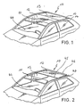
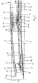
- a vehicle roof 10 (see Fig. 1) comprises a above a windshield 44 pivotally mounted Windabweiserlamelle 11, behind this Windabweiserlamelle 11 lying sliding cover 12 and adjoining the closed lid 12 solid roof panel 13.
- the side Windabweiserlamelle 11, the lid 12 and the roof panel 13 each bounded by a side rail 14.
- the vehicle roof 10 has a completely smooth-surfaced appearance.
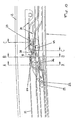
- the cover 12 is slidable rearwardly over the fixed vehicle roof 10 to release a roof opening 15 (see FIG 2), no guides arranged above the fixed vehicle roof 10 are required for this purpose.
- the cover 12 is rather supported by means of laterally hinged in the region of the trailing edge 46 of the lid 12 supporting lever 40, which are movable in below the level of the fixed roof skin guides and which on exit up a flexible sealing element 16 partially displacing, which is arranged between the side rails 14 and the components 11, 12 and 13.
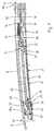
- the necessary for the issuing and moving the lid 12 mechanism is similar to the left and right side of the lid 12, so that only the mechanics of one side described and described below with reference to FIG. 3 to 14 will be explained.
- the opening and shifting mechanism for the cover 12 comprises a guide rail 17, which is formed as a profile part with longitudinally extending guideways.
- a front control slide 18 and a rear control slide 19 are guided longitudinally displaceable.
- the two control slides 18 and 19 are fixedly connected at a mutual distance with a drive cable 21.
- the control slides 18 and 19 are also connected to the front edge 45 and the trailing edge 46 of the lid 12, namely respectively via a slide guide or support lever for lifting and carrying the front edge 45 and the trailing edge 46 of the lid 12 in its adjustment between its closed and its open position, as in the following first for the leading edge 45 and then for the trailing edge 46 of the lid 12th will be explained in detail.
- a lateral vertical cover carrier 22 is arranged on the underside of the lid 12 in the region of the front edge 45 thereof.
- a laterally projecting slide pin 23 is fixedly mounted at a distance from the front edge 45 of the lid 12.
- the slide pin 23 engages in a slide track 24a a lifting link 24 which is fixedly mounted on the front control slide 18 or integrally formed therewith.
- the slide track 24a of the lift gate 24 has a rising from its rear end to its front end in the region of the front edge 45 of the lid 12 course.
- the slide track 24a is formed into an approximately L-shape with a front short bent leg portion and a rear long bent leg portion.
- the sliding pin 23 When the cover 12 is closed, the sliding pin 23 is located in the region of the rear end of the slide track 24a (FIG. 4) and the cover 12 is raised at the front and during the displacement of the cover 12 at the front elevated end of the slide track 24a (see, for example, FIG.
- the slide pin 23 moves in the slide track 24a due to a longitudinal displacement of the control carriage 18 caused by the drive cable 21, wherein the slide pin 23 from its in FIG. 3 with the lid 12 closed, by a rearward displacement of the front control carriage 18 to its upper position, in which the front edge 45 of the lid 12 is raised (see FIG. 7).
- the guide rail 17 further comprises a guide track 26 for the Sliding pin 25 which extends parallel to the carriage guide track 20 in the longitudinal direction of the guide rail 17.
- a link 27 for guiding the front edge 45 of the lid 12 in its raising and lowering movement.
- This gate 27 is fixedly connected to the guide rail 17 and the vehicle roof 10 and has a slide track 28, which adjoins the front end of the sliding pin guide track 26 of the guide rail 17 and extends downwards towards the front.
- the sliding pin 25 (see Figures 3 and 4) is located at the lower end of the slide track 28.
- the sliding pin 25 is largely free of play in the vehicle longitudinal direction (x-direction) and thus determines the exact position of the front edge 45 in the Closed position of the lid 12th
- the exact position of the front edge 45 in the vertical direction is determined by the slide pin 23 which is received in the rear portion of the slide track 24a in the vertical direction substantially free of play.
- the front edge 45 of the lid 12 is raised by means of the Hubkulisse 24 and the sliding pin 23 by backward process of the front control carriage 18, simultaneously moves the sliding pin 25 along the rearwardly rising slide track 28 upwards and finally enters the front end of the sliding pin Guideway 26 of the guide rail 17 (see FIG 7).
- the cover 12 has assumed a position in the region of its front edge 45, from which it can be moved to the rear.
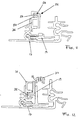
- the cover 12 has, in the region of its trailing edge 46, a lid carrier 30 which extends downwards (see FIG.
- a deployment lever 31 To raise the rear edge or the trailing edge 46 of the lid 12 is a deployment lever 31, the at his The front end is pivotably hinged to the rear steering slide r19 by means of a bearing pin 32 (see Fig. 10) and has a laterally projecting rear slider 33 at its rear end. With the lid closed (FIG. 3), the rear slider 33 engages up to a raised lid position or transfer position (FIG. 7) in a lid guide 34 on the lid carrier 30 which is open towards the rear (see, for example, FIG.
- a slide track 37 of the lifting link 36 extends from the front to the back initially rising, then substantially parallel to the longitudinal direction of the guide rail 17 and then sloping and opening into a guide track 38 of the guide rail 17, which may coincide with the carriage guide track 20.
- a support lever 40 for the trailing edge 46 of the lid 12 is hinged to the lid carrier 30.
- On the bearing pin 39 opposite end of the support lever 40 projects from this laterally a guide pin 41 which is guided in all positions of the trailing edge 46 of the lid 12 in a guide pin track 42 with respect to the former inner guide rail 17 outer guide rail 47.
- the guide pin track 42 extends in the longitudinal direction of the guide rail 47. Instead of the inner guide rail 17 and the outer guide rail 47, only one guide rail may be provided, which contains the said guideways.
- a support pin 43 (see Figure 5), which only after complete lifting of the trailing edge 46 of the lid 12 enters the guide pin track 42 and further movement the lid 12 slides backwards in this guide pin track 42 to support the lid pivoted up on the rear side together with the guide pin 41 guided in the guide pin track 42 instead of the opening lever 31.
- the closing movement of the lid 12 takes place in a coupled coupled forward movement of the two control slides 18 and 19 with a reverse sequence of the pivoting movements of the trailing edge 46 and the front edge 45 of the cover 12th
- engaging elements and preferably locking elements are provided to stabilize the lid in its closed position.
- an upwardly open cam slot 50 is provided on the top of the roof fixed Hubkulisse 36 which is in the lid closing position in engagement with an engaging member 52 which is provided in the upper region of the deployment lever 31.
- the engagement element 52 comprises a laterally projecting locking angle 54, which has a sliding element 56 on its upper end region protruding to the side, which is retracted into the sliding slot 50 in the closed position of the cover and fixes the cover 12 in a roof-fixed manner.
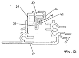
- FIG. Vehicle roof 10 shown locking elements, one of which is designed as a locking tab 48 and the other as a locking angle 49, as shown in FIG. 13 is shown.
- the locking tab 48 is formed on the cover guide 34 as a downwardly facing web in the front region thereof.
- the locking angle 49 protrudes sideways from the deployment lever 31 and engages in the closed position of the lid 12 as shown in FIG. 10, the locking tab 48.
- the rear slider 33 can be at a very strong pressure on the Inside the lid 12 are not rotated about its longitudinal axis from the cover guide 34 or torn out. In the closed position of the lid 12 thus a secure locking of the lid 12 is ensured via the release lever 31 with the guide rail 17 and thus with the fixed vehicle roof 10.
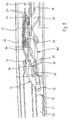
- FIG. 14 a transitional position is shown in which both the engagement members 50 and 52 and the locking members 48 and 49 are about to unlock. It is understood that the arrangement can also be made so that the locking and unlocking of the engagement elements 50 and 52 does not occur simultaneously with the locking or unlocking of the locking elements 48 and 49, but offset.
Description
Die Erfindung betrifft ein Fahrzeugdach mit wenigstens einem an seiner Hinterkante ausstellbaren und verschiebbaren Deckel und mit einer Steuermechanik für den Deckel, die einen nahe der Hinterkante des Deckels an diesem angelenkten hinteren Hub- und Verschiebemechanismus aufweist, der wenigstens einen mit dem Deckel verbundenen Steuerschlitten umfasst, der in seitlichen Führungsschienen verschiebbar geführt und antreibbar ist.The invention relates to a vehicle roof with at least one cover which can be exposed and displaced on its trailing edge and with a control mechanism for the cover, which has a rear lifting and displacing mechanism which is hinged near the trailing edge of the cover and comprises at least one control carriage connected to the cover. which is displaceably guided in lateral guide rails and driven.
Aus der DE 42 38 945 A1 ist ein Fahrzeugdach mit wenigstens einem Deckel bekannt, der zum Öffnen mittels eines Ausstellhebels an seiner Hinterkante anhebbar und anschließend oberhalb des festen Fahrzeugdaches verschiebbar ist. Die Verschiebebewegung erfolgt mittels eines ersten Antriebskabels und die Ausstellbewegung erfolgt mittels eines gegenläufig zu diesem bewegbaren zweiten Antriebskabels. Ein die Ausstellbewegung steuernder Ausstellhebel steht über einen hinteren Schlitten in ständigem Eingriff mit dem einen Antriebskabel, während ein nahe der Vorderkante angeordneter Schlitten, der für die Verschiebebewegung des Deckels zuständig ist, in ständigem Eingriff mit dem gegenläufig hierzu bewegbaren anderen Antriebskabel steht. Durch diese ständige Kopplung ist eine vollständige Trennung der Ausstellbewegung von der Verschiebebewegung nur bedingt möglich und für die Ausstellbewegung steht nur ein relativ kurzer Verfahrweg des Antriebskabels zur Verfügung.From DE 42 38 945 A1 discloses a vehicle roof with at least one lid is known, which can be raised to open by means of a release lever at its rear edge and then slid above the fixed vehicle roof. The displacement movement takes place by means of a first drive cable and the deployment movement takes place by means of a second drive cable movable in opposite directions to this. A deployment lever controlling the deployment lever is in constant engagement with the one drive cable via a rear carriage while a carriage near the leading edge, which is responsible for the sliding movement of the cover, is in constant engagement with the other drive cable movable in opposition thereto. Due to this constant coupling, complete separation of the deployment movement from the displacement movement is only possible to a limited extent, and only a relatively short travel path of the drive cable is available for the deployment movement.
Die Nachteile des vorstehend erläuterten bekannten Fahrzeugdaches werden durch ein Fahrzeugdach der eingangs genannten Art überwunden, das in der DE 197 13 348 C1 offenbart ist. Insbesondere gewährleistet dieses Fahrzeugdach eine klar definierte Position des Deckels während der Ausstellbewegung durch Verriegelung eines die Verstellbewegung des Deckels bewegenden Steuerschlittens während der Ausstellbewegung über einen Riegelstein mit einer dachfesten Führungsschiene. Durch die Entkopplung von der Führungsschiene und gleichzeitige Kopplung mit einem Steuerschlitten wird ein eindeutiger Beginn der Verschiebebewegung definiert, da das erste Antriebskabel nach Beendigung eines Leerweges bei vollendeter Ausstellbewegung den Riegelstein aus seiner Verriegelungsposition mit der Führungsschiene in eine Kopplungsposition des Antriebskabels mit dem Steuerschlitten bewegt.The disadvantages of the above-described known vehicle roof are overcome by a vehicle roof of the type mentioned, which is disclosed in DE 197 13 348 C1. In particular, this vehicle roof ensures a clearly defined position of the lid during the raising movement by locking a control slide moving the adjusting movement of the lid during the raising movement via a locking block with a roof-fixed guide rail. Due to the decoupling of the guide rail and simultaneous coupling with a control slide a clear beginning of the sliding movement is defined, since the first drive cable moves after completion of a free travel in completed Ausstellbewegung the locking block from its locking position with the guide rail in a coupling position of the drive cable with the control slide.
Nachteilig bei den bekannten Dächern ist, dass der Deckel in seiner Schließposition nur über den Ausstellhebel und einen in der Führungsschiene verschiebbaren Schlitten gehalten wird. Wird das mit einem solchen Dach ausgestattete Fahrzeug bei hoher Geschwindigkeit betrieben, so wird der verschiebbare Deckel an seiner Hinterkante aufgrund des durch den über das Fahrzeug hinweg strömenden Luftstrom hervorgerufenen Unterdrucks nach oben gezogen, was schließlich dazu führen kann, dass der Deckel von der am Dachrahmen vorgesehenen Dichtung abgehoben wird. Durch den hierbei entstehenden Spalt werden Geräusche verursacht, die von den Fahrzeuginsassen als störend empfunden werden.A disadvantage of the known roofs is that the lid is held in its closed position only on the deployment lever and a sliding carriage in the guide rail. If the vehicle equipped with such a roof is operated at high speed, the displaceable cover is pulled upwards at its trailing edge due to the negative pressure caused by the air flow passing over the vehicle, which may eventually lead to the cover being displaced from the roof frame lifted seal is lifted. The resulting gap noise is caused, which are perceived by the vehicle occupants as disturbing.
Der Erfindung liegt die Aufgabe zugrunde, ein Fahrzeugdach der eingangs genannten Art zu schaffen, dessen hintere Verstell- und Hubmechanik eine erhöhte Stabilität in der Deckelschließposition aufweist.The invention has for its object to provide a vehicle roof of the aforementioned type, the rear adjustment and lifting mechanism has increased stability in the lid closing position.
Diese Aufgabe wird bei dem eingangs genannten Fahrzeugdach dadurch gelöst, dass ein bewegbares Teil des Hub- und Verschiebemechanismus und ein dachfestes Teil Eingriffselemente aufweisen, die in der Schließposition des Deckels wirksam sind und einem Ausdrücken des Deckels nach oben entgegenwirken.This object is achieved in the vehicle roof mentioned above in that a movable part of the lifting and shifting mechanism and a roof-fixed Part engaging elements which are effective in the closed position of the lid and counteract a pressing of the lid upwards.
Durch die an dem bewegbaren Teil des Hub- und Verschiebemechanismus vorgesehenen Eingriffselemente wird gewährleistet, dass in der Schließposition des Deckels der Deckel und insbesondere dessen Hinterkante sicher mit den dachfesten Eingriffselementen verriegelt ist und auch bei starken auf den hinteren Dekkelbereich einwirkenden Kräften nicht nach oben gezogen wird. Auf diese Weise werden ein Anheben des Deckels von der am Dachrahmen vorgesehenen Dichtung und damit das Entstehen störender Windgeräusche ausgeschlossen.By provided on the movable part of the lifting and displacing mechanism engagement elements ensures that in the closed position of the lid, the lid and in particular the rear edge is securely locked with the roof-mounted engagement elements and is not pulled up even when strong forces acting on the rear Dekkelbereich , In this way, a lifting of the cover of the seal provided on the roof frame and thus the emergence disturbing wind noise are excluded.
Vorteilhafte Weiterbildungen der Erfindung ergeben sich aus den Unteransprüchen.Advantageous developments of the invention will become apparent from the dependent claims.
Während das bewegbare Teil des Hub- und Verschiebemechanismus vorzugsweise von einem Ausstellhebel gebildet wird, kann das dachfeste Teil eine Verriegelungskulisse umfassen, in die das an dem bewegbaren Teil des Hub- und Verschiebemechanismus vorgesehene Eingriffselement beim Schließen des Deckels einfährt.While the movable part of the lifting and shifting mechanism is preferably formed by a deployment lever, the roof-fixed part may comprise a locking link into which engages the engagement element provided on the movable part of the lifting and shifting mechanism when the cover is closed.
Des weiteren kann das Eingriffselement an dem bewegbaren Teil des Hub- und Verschiebemechanismus als ein seitlich vorstehender Sperrwinkel ausgebildet sein, wobei mindestens der seitlich vorstehende Teil des Sperrwinkels vorzugsweise mit einen Gleitelement versehen ist.Furthermore, the engagement element may be formed on the movable part of the lifting and displacing mechanism as a laterally projecting locking angle, wherein at least the laterally projecting part of the blocking angle is preferably provided with a sliding element.
Obschon in der Schließposition des Deckels eine Bewegung des Deckels nach unten grundsätzlich durch die dachfesten Anlageflächen, wie z.B. eine dachfeste Dichtung, ausgeschlossen wird, können, um einer übermäßigen Bewegung des Deckels gegen die dachfeste Dichtung entgegenzuwirken, die Eingriffselemente ferner so gestaltet sein, dass sie in der Schließposition des Deckels einem Ausdrücken des Deckels auch nach unten entgegenwirkenAlthough in the closed position of the lid movement of the lid downwards is basically excluded by the fixed roof contact surfaces, such as a roof-mounted seal, in order to counteract excessive movement of the lid against the roof-mounted seal, the engagement elements may also be designed so that they counteract in the closed position of the lid expressions of the lid also down
Die Stabilität des geschlossenen Fahrzeugdaches lässt sich noch weiter erhöhen, wenn ein bewegbares Teil des Hub- und Verschiebemechanismus und ein mit dem Deckel verbundenes Teil jeweils in der Schließposition des Deckels wirksame Verriegelungselemente aufweisen, die einem Ausdrücken des Deckels nach oben entgegenwirken. Durch die doppelte Verriegelung des Deckels, einerseits mittels der Eingriffselemente und andererseits mittels der Verriegelungselemente, wird gewährleistet, dass der Deckel auch bei einem hohen gegen die Innenseite des Deckels gerichteten Druck, wie er im Crashfall durch den Aufprall eines Fahrzeuginsassen gegen die Deckelunterseite hervorgerufen werden könnte, nicht nach oben aus der Dachöffnung gedrückt werden kann.The stability of the closed vehicle roof can be further increased if a movable part of the lifting and shifting mechanism and a part connected to the cover in each case in the closed position of the lid have effective locking elements which oppose an expression of the lid upwards. Due to the double locking of the lid, on the one hand by means of the engagement elements and on the other hand by means of the locking elements, it is ensured that the lid even at a high directed against the inside of the lid pressure, as it could be caused in the event of a crash by the impact of a vehicle occupant against the lid bottom , can not be pushed up out of the roof opening.
Bei dem bewegbaren Teil des Hub- und Verschiebemechanismus kann es sich hierbei wiederum um einen Ausstellhebel handeln, vorzugsweise um den selben Ausstellhebel, an welchem das dem bewegbaren Teil des Hub- und Verschiebe-mechanismus zugeordnete Eingriffselement vorgesehen ist.The movable part of the lifting and displacing mechanism may in turn be a deployment lever, preferably the same deployment lever, on which the engagement element associated with the movable part of the lifting and shifting mechanism is provided.
Das mit dem Deckel verbundene Teil kann hierbei von einer Deckelführung gebildet werden, die mit einem Teil des Hub- und Verschiebemechanismus in Eingriff steht und die eine Relativbewegung desselben gegenüber dem Deckel beim Ausstellen ermöglicht.The part connected to the lid can in this case be formed by a cover guide, which is in engagement with a part of the lifting and displacing mechanism and which allows a relative movement of the latter relative to the cover when it is exposed.
Die Verriegelungselemente können beispielsweise als nach unten abgebogene bzw. als seitlich und nach oben vorstehende Verriegelungslaschen ausgebildet sein.The locking elements may be formed, for example, as downwardly bent or as laterally and upwardly projecting locking tabs.
Das vorliegend erläuterte Fahrzeugdach ist bevorzugt bei einem solchen Fahrzeug einsetzbar, bei welchem der Deckel oberhalb des festen Fahrzeugdaches nach hinten verschiebbar ist.The presently explained vehicle roof is preferably used in such a vehicle, in which the cover above the fixed vehicle roof is displaced to the rear.
Nachfolgend wird die Erfindung anhand der Zeichnungen beispielhaft näher erdautert. Es zeigen:
- FIG. 1
- eine schematische perspektivische Ansicht eines Fahrzeugdaches mit geschlossenem Deckel,
- FIG. 2
- eine Darstellung gemäß FIG. 1 bei vollständig geöffnetem Deckel,
- FIG. 3
- einen Längsschnitt durch einen Seitenrand des Fahrzeugdaches im Bereich der Ausstellmechanik bei geschlossenem Deckel,
- FIG. 4
- einen Längsschnitt gemäß FIG. 3 durch eine vordere Ausstellmechanik in vergrößerter Darstellung,
- FIG. 5
- einen Längsschnitt gemäß FIG. 3 durch eine hintere Ausstellmechanik in vergrößerter Darstellung,
- FIG. 6
- einen Längsschnitt durch einen Seitenrand des Fahrzeugdaches im Bereich der Ausstellmechanik bei ausgestelltem Deckel,
- FIG. 7
- einen Längsschnitt durch einen Seitenrand des Fahrzeugdaches im Bereich der Ausstellmechanik am Ende einer Übergangsbewegung,
- FIG. 8
- einen Längsschnitt durch einen Seitenrand des Fahrzeugdaches im Bereich der Ausstellmechanik in einer Zwischenstellung,
- FIG. 9
- einen Längsschnitt durch einen Seitenrand des Fahrzeugdaches im Bereich der Ausstellmechanik bei geöffnetem Deckel,
- FIG. 10
- einen Längsschnitt gemäß FIG. 3 durch eine hintere Ausstellmechanik in geschlossener Position des Deckels mit der in Eingriff befindlichen Verriegelung,
- FIG. 11
- einen Querschnitt gemäß der Linie B-B in FIG. 10;
- FIG. 12
- einen Querschnitt gemäß der Linie A-A in FIG. 10;
- FIG. 13
- einen Querschnitt gemäß der Linie C-C in FIG. 10; und
- FIG. 14
- eine Ansicht ähnlich FIG. 10, welche die hintere Ausstellmechanik des Deckels in einer ausgestellten Zwischenposition zeigt, wenn die Eingriffselemente und die Verriegelungselemente gerade entriegeln.
- FIG. 1
- a schematic perspective view of a vehicle roof with a closed lid,
- FIG. 2
- a representation according to FIG. 1 with the lid completely open,
- FIG. 3
- a longitudinal section through a side edge of the vehicle roof in the region of the release mechanism with the lid closed,
- FIG. 4
- a longitudinal section of FIG. 3 by a front Ausstellmechanik in an enlarged view,
- FIG. 5
- a longitudinal section of FIG. 3 by a rear Ausstellmechanik in an enlarged view,
- FIG. 6
- a longitudinal section through a side edge of the vehicle roof in the area of the release mechanism with the lid off,
- FIG. 7
- a longitudinal section through a side edge of the vehicle roof in the region of the release mechanism at the end of a transitional movement,
- FIG. 8th
- a longitudinal section through a side edge of the vehicle roof in the region of the release mechanism in an intermediate position,
- FIG. 9
- a longitudinal section through a side edge of the vehicle roof in the region of the opening mechanism with the lid open,
- FIG. 10
- a longitudinal section of FIG. 3 by a rear release mechanism in the closed position of the lid with the interlock engaged,
- FIG. 11
- a cross section along the line BB in FIG. 10;
- FIG. 12
- a cross section along the line AA in FIG. 10;
- FIG. 13
- a cross section along the line CC in FIG. 10; and
- FIG. 14
- a view similar to FIG. 10, which shows the rear release mechanism of the lid in an intermediate position exhibited when the engagement members and the locking members are about to unlock.
Ein Fahrzeugdach 10 (siehe FIG. 1) umfasst eine oberhalb einer Windschutzscheibe 44 schwenkbar angeordnete Windabweiserlamelle 11, einen hinter dieser Windabweiserlamelle 11 liegenden verschiebbaren Deckel 12 und eine sich an den geschlossenen Deckel 12 anschließende feste Dachscheibe 13. Seitlich werden die Windabweiserlamelle 11, der Deckel 12 und die Dachscheibe 13 jeweils von einem Seitenholm 14 begrenzt.A vehicle roof 10 (see Fig. 1) comprises a above a
Im geschlossenen Zustand gemäß FIG. 1 bietet das Fahrzeugdach 10 ein vollkommen glattflächiges Erscheinungsbild. Obwohl der Deckel 12 zur Freigabe einer Dachöffnung 15 nach hinten über das feste Fahrzeugdach 10 verschiebbar ist (siehe FIG. 2), sind hierzu keinerlei oberhalb des festen Fahrzeugdaches 10 angeordnete Führungen erforderlich. Im ausgestellten und nach hinten verfahrenen Zustand wird der Deckel 12 vielmehr mittels seitlich im Bereich der Hinterkante 46 des Deckels 12 angelenkter Stützhebel 40 abgestützt, welche in unterhalb des Niveaus der festen Dachhaut angeordneten Führungen verfahrbar sind und welche beim Austreten nach oben ein flexibles Dichtelement 16 teilweise verdrängen, welches zwischen den Seitenholmen 14 und den Bauteilen 11, 12 und 13 angeordnet ist.In the closed state according to FIG. 1, the
Die für das Ausstellen und Verschieben des Deckels 12 erforderliche Mechanik ist an der linken und rechten Seite des Deckels 12 gleichartig aufgebaut, so dass lediglich die Mechanik der einen Seite beschrieben und nachfolgend anhand der FIG. 3 bis 14 erläutert wird.The necessary for the issuing and moving the
Die Ausstell- und Verschiebemechanik für den Deckel 12 umfasst eine Führungsschiene 17, die als Profilteil mit in Längsrichtung verlaufenden Führungsbahnen gebildet ist. In einer unteren Führungsbahn 20 sind ein vorderer Steuerschlitten 18 und ein hinterer Steuerschlitten 19 längsverschiebbar geführt. Die beiden Steuerschlitten 18 und 19 sind unter gegenseitigem Abstand mit einem Antriebskabel 21 fest verbunden. Die Steuerschlitten 18 und 19 sind außerdem mit der Vorderkante 45 bzw. der Hinterkante 46 des Deckels 12 verbunden, und zwar jeweils über eine Kulissenführung bzw. Stützhebel zum Anheben und Tragen der Vorderkante 45 bzw. der Hinterkante 46 des Deckels 12 bei dessen Verstellung zwischen seiner Schließ- und seiner Öffnungsposition, wie im folgenden zunächst für die Vorderkante 45 und dann für die Hinterkante 46 des Deckels 12 im einzelnen erläutert wird.The opening and shifting mechanism for the
Wie insbesondere in FIG. 4 dargestellt ist, ist an der Unterseite des Deckels 12 im Bereich von dessen Vorderkante 45 ein seitlicher vertikaler Deckelträger 22 angeordnet. Am unteren Rand des Deckelträgers 22 ist ein seitlich hervorstehender Gleitzapfen 23 mit Abstand von der Vorderkante 45 des Deckels 12 fest angebracht. Der Gleitzapfen 23 greift in eine Kulissenbahn 24a einer Hubkulisse 24 ein, die am vorderen Steuerschlitten 18 fest angebracht bzw. einstückig mit diesem gebildet ist. Die Kulissenbahn 24a der Hubkulisse 24 weist einen von ihrem hinteren Ende zu ihrem vorderen Ende im Bereich der Vorderkante 45 des Dekkels 12 ansteigenden Verlauf auf. Insbesondere ist die Kulissenbahn 24a in etwa L-förmig mit einem vorderen kurzen gebogenen Schenkelabschnitt und einem hinteren langen gebogenen Schenkelabschnitt gebildet. Der Gleitzapfen 23 befindet sich bei geschlossenem Deckel 12 im Bereich des hinteren Endes der Kulissenbahn 24a (FIG. 4) und bei vorne angehobenem Deckel 12 sowie während der Verschiebung des Deckels 12 am vorderen erhöhten Ende der Kulissenbahn 24a (siehe z.B. FIG. 7). Der Gleitzapfen 23 bewegt sich in der Kulissenbahn 24a aufgrund einer durch das Antriebskabel 21 bewirkten Längsverschiebung des Steuerschlittens 18, wobei der Gleitzapfen 23 aus seiner in FIG. 3 gezeigten unteren Position bei geschlossenem Deckel 12 durch eine rückwärts gerichtete Verschiebung des vorderen Steuerschlittens 18 in seine obere Position gelangt, in welcher die Vorderkante 45 des Deckels 12 angehoben ist (siehe FIG. 7).As particularly shown in FIG. 4, a lateral
Von dem Deckelträger 22 steht seitlich ein Schiebezapfen 25 hervor, der ebenfalls am unteren Rand des Deckelträgers 22 angebracht ist und bei der dargestellten Ausführungsform in Fahrzeuglängsrichtung vor dem Gleitzapfen 23 liegt. Die Führungsschiene 17 umfasst des weiteren eine Führungsbahn 26 für den Schiebezapfen 25, die parallel zur Schlittenführungsbahn 20 in Längsrichtung der Führungsschiene 17 verläuft. An das Vorderende der Schiebezapfen-Führungsbahn 26 schließt sich eine Kulisse 27 zur Führung der Vorderkante 45 des Dekkels 12 bei dessen Ausstell- und Absenkbewegung an. Diese Kulisse 27 ist fest mit der Führungsschiene 17 bzw. dem Fahrzeugdach 10 verbunden und besitzt eine Kulissenbahn 28, die sich an das Vorderende der Schiebezapfen-Führungsbahn 26 der Führungsschiene 17 anschließt und nach vorne abwärts verläuft. Bei geschlossenem Deckel 12 befindet sich der Schiebezapfen 25 (siehe FIGN. 3 und 4) am unteren Ende der Kulissenbahn 28. Der Schiebezapfen 25 ist in der Fahrzeuglängsrichtung (x-Richtung) weitgehend spielfrei geführt und bestimmt damit die exakte Position der Vorderkante 45 in der Schließstellung des Deckels 12.From the
Die exakte Position der Vorderkante 45 in vertikaler Richtung (z-Richtung) wird durch den Gleitzapfen 23 bestimmt, der in dem Hinterabschnitt der Kulissenbahn 24a in vertikaler Richtung im wesentlichen spielfrei aufgenommen ist. Wenn die Vorderkante 45 des Deckels 12 mittels der Hubkulisse 24 und dem Gleitzapfen 23 durch nach hinten Verfahren des vorderen Steuerschlittens 18 angehoben wird, bewegt sich gleichzeitig der Schiebezapfen 25 entlang der nach hinten ansteigenden Kulissenbahn 28 nach oben und tritt schließlich in das Vorderende der Schiebezapfen-Führungsbahn 26 der Führungsschiene 17 ein (siehe FIG. 7). Nun hat der Deckel 12 im Bereich seiner Vorderkante 45 eine Stellung eingenommen, aus der er nach hinten verschoben werden kann.The exact position of the
Nachfolgend wird der Hub- und Verschiebemechanismus im Bereich der Hinterkante 46 des Deckels 12 anhand einer Längsverschiebung des hinteren Führungsschlittens 19 über das Antriebskabel 21 erläutert.Subsequently, the lifting and displacement mechanism in the region of the trailing
Der Deckel 12 weist im Bereich seiner Hinterkante 46 einen sich abwärts erstrekkenden Deckelträger 30 auf (siehe FIG. 6). Zum Anheben des Hinterrandes bzw. der Hinterkante 46 des Deckels 12 dient ein Ausstellhebel 31, der an seinem Vorderende mittels eines Lagerbolzens 32 (siehe FIG. 10) schwenkbar am hinteren.iSteuerschlittenr19 angelenkt ist und der an seinem Hinterende einen seitlich hervorstehenden hinteren Gleiter 33 aufweist. Der hintere Gleiter 33 greift bei geschlossenem Deckel (FIG. 3) bis zu einer angehobenen Deckelposition bzw. Übergabestellung (FIG. 7) in eine Deckelführung 34 an dem Deckelträger 30 ein, welche nach hinten offen ist (siehe beispielsweise FIG. 6). Zwischen dem Lagerbolzen 32 und dem hinteren Gleiter 33 steht seitlich von dem Ausstellhebel 31 ein vorderer Gleiter 35 vor, der in einer führungsschienenfesten Hubkulisse 36 gleitend geführt ist. Eine Kulissenbahn 37 der Hubkulisse 36 verläuft von vorne nach hinten zunächst ansteigend, daraufhin im wesentlichen parallel zur Längsrichtung der Führungsschiene 17 und dann abfallend und in eine Führungsbahn 38 der Führungsschiene 17 mündend, die mit der Schlittenführungsbahn 20 zusammenfallen kann.The
Mittels eines Lagerstifts 39 ist ein Stützhebel 40 für die Hinterkante 46 des Dekkels 12 an dem Deckelträger 30 angelenkt. Am dem Lagerstift 39 gegenüberliegenden Ende des Stützhebels 40 steht von diesem seitlich ein Führungszapfen 41 vor, der in sämtlichen Positionen der Hinterkante 46 des Deckels 12 in einer Führungszapfenbahn 42 einer bezüglich der erstgenannten inneren Führungsschiene 17 äußeren Führungsschiene 47 geführt ist. Die Führungszapfenbahn 42 verläuft in Längsrichtung der Führungsschiene 47. Statt der inneren Führungsschiene 17 und der äußeren Führungsschiene 47 kann auch nur eine Führungsschiene vorgesehen sein, welche die genannten Führungsbahnen enthält.By means of a
In etwa in der Mitte zwischen dem Lagerstift 39 und dem Führungszapfen 41 steht seitlich von dem Stützhebel 40 ein Stützzapfen 43 hervor (siehe FIG. 5), der erst nach vollständigem Anheben der Hinterkante 46 des Deckels 12 in die Führungszapfenbahn 42 eintritt und bei weiterem Verschieben des Deckels 12 nach hinten in dieser Führungszapfenbahn 42 gleitet, um den rückseitig hochgeschwenkten Deckel 12 gemeinsam mit dem in der Führungszapfenbahn 42 geführten Führungszapfen 41 anstelle des Ausstellhebels 31 abzustützen.Approximately in the middle between the bearing
Anhand der Figuren 5 bis 14 wird nachfolgend das Anheben der Hinterkante 46 des Deckels 12 bis in die Deckelöffnungsstellung gemäß FIG. 9 erläutert.The lifting of the trailing
Wenn der hintere Steuerschlitten 19 ausgehend von der Deckelschließposition (siehe FIGN. 3 und 5) mittels des Antriebskabels 21 nach hinten bewegt wird, bewegt sich der vordere Gleiter 35 des Ausstellhebels 31 zunächst in dem vorderen ansteigenden Abschnitt der Kulissenbahn 37 der Hubkulisse 36 aufwärts (FIG. 6), so dass der aufwärts geschwenkte Ausstellhebel 31 mittels des hinteren Gleiters 33, der in der Deckelführung 34 geführt ist, die Hinterkante 46 des Deckels 12 über das feste Dach ausstellt. In der in FIG. 6 gezeigten Position tritt der bislang nicht eingerückte Stützzapfen 43 in die Führungszapfenbahn 42 ein und gleitet nun bei weiterer Rückwärtsbewegung des hinteren Steuerschlittens 19 gemeinsam mit dem vor ihm gleitenden Führungszapfen 41 entlang der Führungszapfenbahn 42 unter Abstützung des Deckels 12 unter einem vorgegebenen Ausstellwinkel nach hinten. Bei der Bewegung des hinteren Steuerschlittens 19 von der in FIG. 3 bzw. 5 gezeigten Position in die in FIG. 6 gezeigte Position, in welcher die Hinterkante 46 des Deckels 12 ausgestellt ist, bewegt sich der hintere Gleiter 33 vom vorderen Ende der Deckelführung 34 zu deren hinterem offenen Ende, aus welchem der hintere Gleiter 33 bei einer weiteren Rückwärtsbewegung des hinteren Steuerschlittens 19 austritt (siehe FIG. 7, welche die Übergabestellung wiedergibt). Während des Übergangs von der in FIG. 6 gezeigten Position zu der in FIG. 7 gezeigten Position bewegt sich der vordere Gleiter 35 entlang des waagrechten Teils der Kulissenbahn 37 der Hubkulisse 36 und gelangt daraufhin in den abfallenden Teil der Kulissenbahn 37, so dass der Ausstellhebel 31 wieder nach unten in etwa in eine horizontale Stellung geschwenkt wird.When the
Bei einer weiteren Rückwärtsbewegung des hinteren Steuerschlittens 19 tritt der vordere Gleiter 35 in die Führungsbahn 38 ein, die den Ausstellhebel 31 während einer weiteren Rückwärtsbewegung des Steuerschlittens 19 in seine abgesenkte horizontale Stellung führt, in der er funktionslos ist. Die angehobene Position der Hinterkante 46 des Deckels 12 wird nun ausschließlich durch den Stützhebel 40 aufrechterhalten, dessen beide Zapfen 41 und 43 in der Führungszapfenbahn 42 geführt sind.In a further rearward movement of the
Die Schließbewegung des Deckels 12 erfolgt bei einem gemeinsamen gekoppelten Vorwärtslauf der beiden Steuerschlitten 18 und 19 mit umgekehrter Abfolge der Schwenkbewegungen der Hinterkante 46 und der Vorderkante 45 des Dekkels 12.The closing movement of the
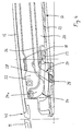
Wie am besten aus den FIGN. 10 bis 13 zu entnehmen ist, sind gemäß der Erfindung Eingriffselemente sowie vorzugsweise Verriegelungselemente vorgesehen, um den Deckel in seiner Schließposition zu stabilisieren. Bei der in FIG. 10 dargestellten Ausführungsform ist an der Oberseite der dachfesten Hubkulisse 36 ein nach oben offener Kulissenschlitz 50 vorgesehen, der in der Deckelschließposition in Eingriff mit einem Eingriffselement 52 steht, das im oberen Bereich des Ausstellhebels 31 vorgesehen ist.As best of the FIGN. 10 to 13 can be seen, according to the invention engaging elements and preferably locking elements are provided to stabilize the lid in its closed position. In the in FIG. 10 illustrated embodiment, an upwardly
Wie am besten der FIG. 11 zu entnehmen ist, umfasst das Eingriffselement 52 einen seitlich vorstehenden Sperrwinkel 54, der an seinem oberen, zur Seite abstehenden Endbereich ein Gleitelement 56 aufweist, das in der geschlossenen Position des Deckels in den Kulissenschlitz 50 eingefahren ist und den Deckel 12 dachfest fixiert. Darüber hinaus weist das in den FIG. 10 gezeigte Fahrzeugdach Verriegelungselemente auf, von denen eines als Verriegelungslasche 48 und das andere als Verriegelungswinkel 49 ausgebildet ist, wie dies auch in FIG. 13 dargestellt ist. Die Verriegelungslasche 48 ist an der Deckelführung 34 als nach unten weisender Steg in deren vorderem Bereich ausgebildet.As best of FIG. 11, the
Der Verriegelungswinkel 49 steht seitwärts vom Ausstellhebel 31 vor und umgreift in der Schließposition des Deckels 12 gemäß FIG. 10 die Verriegelungslasche 48. Durch dieses Umgreifen des Verriegelungswinkels 49 um die Verriegelungslasche 48 kann der hintere Gleiter 33 auch bei einem sehr starken Druck auf die Innenseite des Deckels 12 nicht um seine Längsachse aus der Deckelführung 34 herausgedreht bzw. herausgerissen werden. In der Schließposition des Deckels 12 ist somit eine sichere Verriegelung des Deckels 12 über den Ausstellhebel 31 mit der Führungsschiene 17 und somit mit dem festen Fahrzeugdach 10 gewährleistet.The locking
In FIG. 14 ist eine Übergangsposition dargestellt, in welcher sowohl die Eingriffselemente 50 und 52 als auch die Verriegelungselemente 48 und 49 gerade entriegeln. Es versteht sich, dass die Anordnung auch so getroffen sein kann, dass das Ver- und Entriegeln der Eingriffselemente 50 und 52 nicht gleichzeitig mit dem Ver- bzw. Entriegeln der Verriegelungselemente 48 und 49 erfolgt, sondern versetzt dazu.In FIG. 14, a transitional position is shown in which both the
- 1010
- Fahrzeugdachvehicle roof
- 1111
- Windabweiserlamellewind deflector
- 1212
- Deckelcover
- 1313
- DachscheibeDachscheibe
- 1414
- Seitenholmside rail
- 1515
- Dachöffnungroof opening
- 1616
- Dichtelementsealing element
- 1717
- Führungsschieneguide rail
- 1818
- vorderer Steuerschlittenfront control slide
- 1919
- hinterer Steuerschlittenrear control slide
- 2020
- SchlittenführungsbahnSlide guideway
- 2121
- Antriebskabeldrive cable
- 2222
- Deckelträgercover carrier
- 2323
- Gleitzapfensliding pin
- 2424
- Hubkulisselifting slot
- 24a24a
- Kulissenbahnlink path
- 2525
- Schiebezapfensliding pin
- 2626
- Schiebezapfen-FührungsbahnSliding pin guide path
- 2727
- Kulissescenery
- 2828
- Kulissenbahnlink path
- 3030
- Deckelträgercover carrier
- 3131
- Ausstellhebelout lever
- 3232
- Lagerbolzenbearing bolt
- 3333
- hinterer Gleiter (an 31)rear glider (at 31)
- 3434
- Deckelführungcover guide
- 3535
- vorderer Gleiter (an 31)front glider (at 31)
- 3636
- Hubkulisselifting slot
- 3737
- Kulissenbahnlink path
- 3838
- Führungsbahnguideway
- 3939
- Lagerstiftbearing pin
- 4040
- Stützhebelsupport lever
- 4141
- Führungszapfenspigot
- 4242
- FührungszapfenbahnGuide pin path
- 4343
- Stützzapfensupporting pin
- 4444
- WindschutzscheibeWindshield
- 4545
- Vorderkante (von 12)Leading edge (from 12)
- 4646
- Hinterkante (von 12)Trailing edge (from 12)
- 4747
- äußere Führungsschieneouter guide rail
- 4848
- Verriegelungslaschelocking tab
- 4949
- Verriegelungswinkellocking angle
- 5050
- Kulissenschlitzlink slot
- 5252
- Eingriffselement (an 31)Engagement element (at 31)
- 5454
- Sperrwinkelblocking angle
- 5656
- GleitelementSlide
Claims (15)
- Vehicle roof comprising at least one panel (12) which can be opened at its rear edge (46) and displaced, and having a control mechanism for the panel (12) which has a lifting and displacing mechanism (19, 31) attached to the panel (12) close to the rear edge (46) of the latter and which comprises at least one control slide (19) which is connected to the panel (12) and is guided in lateral guide rails (17) such that it can be displaced and driven, characterized in that a movable part (31) of the lifting and displacing mechanism and a part (36) fixed to the roof have engaging elements (50, 52) which are effective in the closed position of the panel (12) and counteract the panel (12) being forced out upwards.
- Vehicle roof according to Claim 1, characterized in that the movable part of the lifting and displacing mechanism (19, 31) is formed by an opening lever (31).
- Vehicle roof according to Claim 1 or 2, characterized in that the part (36) fixed to the roof comprises a locking slotted guide (50), into which the engaging element (52) provided on the movable part (31) of the lifting and displacing mechanism moves as the panel (12) is closed.
- Vehicle roof according to one of the preceding claims, characterized in that the engaging element (52) on the movable part (31) of the lifting and displacing mechanism is formed as a blocking angle (54) that projects laterally.
- Vehicle roof according to Claim 4, characterized in that at least the laterally projecting part of the blocking angle (54) is provided with a sliding element (56).
- Vehicle roof according to one of the preceding claims, characterized in that, in the closed position of the panel (12), the engaging elements (50, 52) counteract the panel (12) being forced out downwards.
- Vehicle roof according to one of the preceding claims, characterized in that a movable part (31) of the lifting and displacing mechanism (19, 31) and a part (22, 34) connected to the panel (12) have locking elements (48 and 49) which are each effective in the closed position of the panel (12) and counteract the panel (12) being forced out upwards.
- Vehicle roof according to Claim 7, characterized in that the movable part of the lifting and displacing mechanism (19, 31) is formed by an opening lever (31).
- Vehicle roof according to Claim 7, characterized in that the engaging element (52) provided on a movable part of the lifting and displacing mechanism (19, 31), and the locking element (49) provided on a movable part of the lifting and displacing mechanism, are provided on one and the same opening lever (31).
- Vehicle roof according to one of Claims 7 to 9, characterized in that the part connected to the panel (12) is formed by a panel guide (34), which is in engagement with a part (33) of the lifting and displacing mechanism (19, 31) and permits a relative movement of the same with respect to the panel (12) during opening.
- Vehicle roof according to one of Claims 7 to 10, characterized in that the locking element on the part (34) connected to the panel (12) is formed as a locking lug (49) that is bent over downwards.
- Vehicle roof according to one of Claims 7 to 11, characterized in that the locking element on the movable part (31) of the lifting and displacing mechanism is formed as a locking angle (49) that projects laterally and upwards.
- Vehicle roof according to one of the preceding claims, characterized in that the panel (12) can be displaced rearwards above the fixed vehicle roof (10).
- Vehicle roof according to one of the preceding claims, characterized in that the lifting and displacing mechanism comprises an opening lever (31) which is attached to a rear control slide (19) such that it can be pivoted, during a rearward movement of the rear control slide (19) is raised by a slotted lifting guide (36) fixed to the roof in order to raise the rear edge (46) of the panel (12) and, in the process, brings the engaging elements and the locking elements (48, 49) out of active engagement.
- Vehicle roof according to Claim 14, characterized in that, after the engaging elements and the locking elements (48, 49) have been disengaged, the opening lever (31) is disengaged from the panel (12) and, in the process, transfers the support of the rear edge (46) of the panel (12) to a separate supporting lever (40).
Applications Claiming Priority (2)
| Application Number | Priority Date | Filing Date | Title |
|---|---|---|---|
| DE2001140389 DE10140389C2 (en) | 2001-08-23 | 2001-08-23 | vehicle roof |
| DE10140389 | 2001-08-23 |
Publications (2)
| Publication Number | Publication Date |
|---|---|
| EP1285798A1 EP1285798A1 (en) | 2003-02-26 |
| EP1285798B1 true EP1285798B1 (en) | 2006-05-24 |
Family
ID=7695765
Family Applications (1)
| Application Number | Title | Priority Date | Filing Date |
|---|---|---|---|
| EP20020018463 Expired - Fee Related EP1285798B1 (en) | 2001-08-23 | 2002-08-16 | Spoiler vehicle roof |
Country Status (3)
| Country | Link |
|---|---|
| EP (1) | EP1285798B1 (en) |
| JP (1) | JP2003072378A (en) |
| DE (2) | DE10140389C2 (en) |
Families Citing this family (6)
| Publication number | Priority date | Publication date | Assignee | Title |
|---|---|---|---|---|
| DE10329536B4 (en) | 2003-06-30 | 2007-07-19 | Webasto Ag | vehicle roof |
| DE102006060019B4 (en) * | 2006-12-19 | 2009-01-08 | Webasto Ag | vehicle roof |
| DE102008024948B4 (en) * | 2008-05-23 | 2010-04-08 | Webasto Ag | Space-optimized drive mechanism for cover element |
| DE202010012974U1 (en) * | 2010-11-24 | 2012-02-27 | Inalfa Roof Systems Group B.V. | Open roof construction for a vehicle |
| EP2727755B1 (en) * | 2012-10-30 | 2015-10-21 | Inalfa Roof Systems Group B.V. | Open roof construction for a vehicle |
| DE102019104981A1 (en) * | 2019-02-27 | 2020-08-27 | Webasto SE | Openable vehicle roof with a lid |
Family Cites Families (7)
| Publication number | Priority date | Publication date | Assignee | Title |
|---|---|---|---|---|
| DE3238454C2 (en) * | 1982-10-16 | 1984-11-29 | Webasto-Werk W. Baier GmbH & Co, 8035 Gauting | Sunroof for vehicles |
| NL9001686A (en) * | 1990-07-25 | 1992-02-17 | Vermeulen Hollandia Octrooien | ROOF PANEL ASSEMBLY FOR A MOTOR VEHICLE. |
| IT1261560B (en) * | 1993-08-11 | 1996-05-23 | DEVICE FOR OPENING AND CLOSING A CAR ROOF | |
| DE9410631U1 (en) * | 1994-07-01 | 1995-11-02 | Farmont Rolf | sunroof |
| DE19713348C1 (en) * | 1997-03-29 | 1998-07-09 | Webasto Karosseriesysteme | Motor vehicle roof with sliding section |
| US6199944B1 (en) * | 1999-06-04 | 2001-03-13 | Asc Incorporated | Spoiler sunroof |
| DE10023314C1 (en) * | 2000-05-15 | 2001-08-09 | Webasto Vehicle Sys Int Gmbh | Openable vehicle roof with lockable lid |
-
2001
- 2001-08-23 DE DE2001140389 patent/DE10140389C2/en not_active Expired - Fee Related
-
2002
- 2002-08-16 EP EP20020018463 patent/EP1285798B1/en not_active Expired - Fee Related
- 2002-08-16 DE DE50206864T patent/DE50206864D1/en not_active Expired - Lifetime
- 2002-08-20 JP JP2002239826A patent/JP2003072378A/en active Pending
Also Published As
| Publication number | Publication date |
|---|---|
| JP2003072378A (en) | 2003-03-12 |
| DE10140389A1 (en) | 2003-03-13 |
| DE10140389C2 (en) | 2003-11-27 |
| DE50206864D1 (en) | 2006-06-29 |
| EP1285798A1 (en) | 2003-02-26 |
Similar Documents
| Publication | Publication Date | Title |
|---|---|---|
| EP1172243B1 (en) | Vehicle roof provided with at least a panel sliding above the rigid part of the roof | |
| EP1223065B1 (en) | Vehicle roof | |
| DE102006002064B4 (en) | Vehicle roof with a sliding above a fixed roof section lid | |
| EP0381066B1 (en) | Vehicle roof with a roof cutout closable by a cover | |
| DE102005007031B4 (en) | Vehicle roof with a sliding above the roof roof part | |
| EP2451665B2 (en) | Sliding roof device, in particular for a motor vehicle | |
| DE102005007032B4 (en) | Vehicle roof with a sliding above the roof roof part | |
| DE102006062543B4 (en) | Vehicle roof with a sliding above the roof roof part | |
| EP1844967A1 (en) | Slidable sun roof system | |
| DE3425271A1 (en) | VEHICLE ROOF | |
| EP1500539A1 (en) | Open roof for vehicle | |
| DE102016106001B4 (en) | Vehicle roof arrangement, vehicle roof and method | |
| EP1922220B1 (en) | Vehicle roof with at least two cover elements | |
| DE10158174B4 (en) | Sunroof for vehicles | |
| EP1285798B1 (en) | Spoiler vehicle roof | |
| WO2007076784A1 (en) | Vehicle roof with at least one cover which can be moved above a fixed vehicle roof | |
| WO2021130001A1 (en) | Vehicle roof comprising a roof opening system having two kinematics units | |
| DE202007001217U1 (en) | Automotive roof has fixed rear panel and front panel that slides through side guides | |
| EP2468548B1 (en) | Adjustment device for a top bow for a foldable roof | |
| DE102005059288B4 (en) | Vehicle roof with at least one above a fixed vehicle roof sliding cover | |
| DE10226110B4 (en) | vehicle roof | |
| DE102007003354B4 (en) | Vehicle roof with a sliding above the roof roof part | |
| DE102007004694B4 (en) | Vehicle roof with an openable roof part | |
| WO2007065417A1 (en) | Guide mechanism for a sunroof sunroof and motor vehicle with sunroof | |
| WO2021180718A1 (en) | Vehicle roof comprising a roof opening system having two kinematics units |
Legal Events
| Date | Code | Title | Description |
|---|---|---|---|
| PUAI | Public reference made under article 153(3) epc to a published international application that has entered the european phase |
Free format text: ORIGINAL CODE: 0009012 |
|
| AK | Designated contracting states |
Kind code of ref document: A1 Designated state(s): AT BE BG CH CY CZ DE DK EE ES FI FR GB GR IE IT LI LU MC NL PT SE SK TR |
|
| AX | Request for extension of the european patent |
Extension state: AL LT LV MK RO SI |
|
| 17P | Request for examination filed |
Effective date: 20030729 |
|
| AKX | Designation fees paid |
Designated state(s): DE FR GB NL |
|
| GRAP | Despatch of communication of intention to grant a patent |
Free format text: ORIGINAL CODE: EPIDOSNIGR1 |
|
| GRAS | Grant fee paid |
Free format text: ORIGINAL CODE: EPIDOSNIGR3 |
|
| GRAA | (expected) grant |
Free format text: ORIGINAL CODE: 0009210 |
|
| STAA | Information on the status of an ep patent application or granted ep patent |
Free format text: STATUS: THE PATENT HAS BEEN GRANTED |
|
| AK | Designated contracting states |
Kind code of ref document: B1 Designated state(s): DE FR GB NL |
|
| REG | Reference to a national code |
Ref country code: GB Ref legal event code: FG4D Free format text: NOT ENGLISH |
|
| REF | Corresponds to: |
Ref document number: 50206864 Country of ref document: DE Date of ref document: 20060629 Kind code of ref document: P |
|
| GBT | Gb: translation of ep patent filed (gb section 77(6)(a)/1977) |
Effective date: 20060619 |
|
| ET | Fr: translation filed | ||
| PLBE | No opposition filed within time limit |
Free format text: ORIGINAL CODE: 0009261 |
|
| STAA | Information on the status of an ep patent application or granted ep patent |
Free format text: STATUS: NO OPPOSITION FILED WITHIN TIME LIMIT |
|
| 26N | No opposition filed |
Effective date: 20070227 |
|
| REG | Reference to a national code |
Ref country code: FR Ref legal event code: PLFP Year of fee payment: 15 |
|
| REG | Reference to a national code |
Ref country code: FR Ref legal event code: PLFP Year of fee payment: 16 |
|
| REG | Reference to a national code |
Ref country code: FR Ref legal event code: PLFP Year of fee payment: 17 |
|
| PGFP | Annual fee paid to national office [announced via postgrant information from national office to epo] |
Ref country code: NL Payment date: 20190821 Year of fee payment: 18 |
|
| PGFP | Annual fee paid to national office [announced via postgrant information from national office to epo] |
Ref country code: DE Payment date: 20190822 Year of fee payment: 18 Ref country code: FR Payment date: 20190822 Year of fee payment: 18 |
|
| PGFP | Annual fee paid to national office [announced via postgrant information from national office to epo] |
Ref country code: GB Payment date: 20190827 Year of fee payment: 18 |
|
| REG | Reference to a national code |
Ref country code: DE Ref legal event code: R119 Ref document number: 50206864 Country of ref document: DE |
|
| REG | Reference to a national code |
Ref country code: NL Ref legal event code: MM Effective date: 20200901 |
|
| GBPC | Gb: european patent ceased through non-payment of renewal fee |
Effective date: 20200816 |
|
| PG25 | Lapsed in a contracting state [announced via postgrant information from national office to epo] |
Ref country code: FR Free format text: LAPSE BECAUSE OF NON-PAYMENT OF DUE FEES Effective date: 20200831 Ref country code: DE Free format text: LAPSE BECAUSE OF NON-PAYMENT OF DUE FEES Effective date: 20210302 |
|
| PG25 | Lapsed in a contracting state [announced via postgrant information from national office to epo] |
Ref country code: GB Free format text: LAPSE BECAUSE OF NON-PAYMENT OF DUE FEES Effective date: 20200816 |
|
| PG25 | Lapsed in a contracting state [announced via postgrant information from national office to epo] |
Ref country code: NL Free format text: LAPSE BECAUSE OF NON-PAYMENT OF DUE FEES Effective date: 20200901 |