EP1285712A1 - Hydraulisch betätigter Spannzylinder sowie Verfahren zur Montage eines Spannzylinders - Google Patents
Hydraulisch betätigter Spannzylinder sowie Verfahren zur Montage eines Spannzylinders Download PDFInfo
- Publication number
- EP1285712A1 EP1285712A1 EP02007965A EP02007965A EP1285712A1 EP 1285712 A1 EP1285712 A1 EP 1285712A1 EP 02007965 A EP02007965 A EP 02007965A EP 02007965 A EP02007965 A EP 02007965A EP 1285712 A1 EP1285712 A1 EP 1285712A1
- Authority
- EP
- European Patent Office
- Prior art keywords
- distributor
- housing
- hollow shaft
- cylinder according
- clamping cylinder
- Prior art date
- Legal status (The legal status is an assumption and is not a legal conclusion. Google has not performed a legal analysis and makes no representation as to the accuracy of the status listed.)
- Withdrawn
Links
- 238000000034 method Methods 0.000 title claims description 8
- 230000005540 biological transmission Effects 0.000 claims description 4
- 125000006850 spacer group Chemical group 0.000 claims description 4
- 238000006073 displacement reaction Methods 0.000 claims description 3
- 238000009826 distribution Methods 0.000 abstract description 24
- 239000012530 fluid Substances 0.000 abstract 1
- 238000004519 manufacturing process Methods 0.000 description 2
- 238000002955 isolation Methods 0.000 description 1
- 230000000750 progressive effect Effects 0.000 description 1
- 238000003860 storage Methods 0.000 description 1
Images


Classifications
-
- B—PERFORMING OPERATIONS; TRANSPORTING
- B23—MACHINE TOOLS; METAL-WORKING NOT OTHERWISE PROVIDED FOR
- B23Q—DETAILS, COMPONENTS, OR ACCESSORIES FOR MACHINE TOOLS, e.g. ARRANGEMENTS FOR COPYING OR CONTROLLING; MACHINE TOOLS IN GENERAL CHARACTERISED BY THE CONSTRUCTION OF PARTICULAR DETAILS OR COMPONENTS; COMBINATIONS OR ASSOCIATIONS OF METAL-WORKING MACHINES, NOT DIRECTED TO A PARTICULAR RESULT
- B23Q1/00—Members which are comprised in the general build-up of a form of machine, particularly relatively large fixed members
- B23Q1/0009—Energy-transferring means or control lines for movable machine parts; Control panels or boxes; Control parts
- B23Q1/0018—Energy-transferring means or control lines for movable machine parts; Control panels or boxes; Control parts comprising hydraulic means
-
- B—PERFORMING OPERATIONS; TRANSPORTING
- B23—MACHINE TOOLS; METAL-WORKING NOT OTHERWISE PROVIDED FOR
- B23B—TURNING; BORING
- B23B31/00—Chucks; Expansion mandrels; Adaptations thereof for remote control
- B23B31/02—Chucks
- B23B31/24—Chucks characterised by features relating primarily to remote control of the gripping means
- B23B31/30—Chucks characterised by features relating primarily to remote control of the gripping means using fluid-pressure means in the chuck
- B23B31/302—Hydraulic equipment, e.g. pistons, valves, rotary joints
Definitions
- the invention relates to a hydraulically operated Clamping cylinders for clamping devices on machine tools, with a work spindle that can be driven in rotation the machine tool coupled cylinder housing and one axially adjustable cylinder pistons in the cylinder chamber, as well as with a distributor that has a fixed, the Distributor housing with pressure medium connections and one connected to the cylinder housing, the Distributor hollow shaft with pressure medium lines includes.
- the invention further relates to a method for Assembly of a clamping cylinder.
- Tensioning cylinders of the type mentioned are from the Known in practice and for example in DE 198 23 823 C2 described.
- the medium supply via the non-rotating distributor, by means of roller bearings on the hub-like extension of the cylinder housing is mounted.
- the gap between the standing distributor and the rotating cylinder housing hub can be determined.
- Medium transmission after as a result of the meantime achievable high rotational speeds with contact seals are no longer working can.
- the invention has for its object a To design tensioning cylinders of the type mentioned at the beginning that the above-mentioned residual vibrations continue can be reduced.
- the object of the invention is furthermore, to specify a method such as a tension cylinder is to be mounted to the remaining vibrations largely or to eliminate completely.
- the part of the task relating to the device is at a clamping cylinder of the type mentioned solved that the distributor housing via a receiving bell that the distributor is attached to the machine tool one between the junction box and the Distributor hollow shaft arranged distributor bushing, and that the distributor socket between a first Position that the assembly of the distributor and its Centering serves, and a second position adjustable is in the distribution game for the medium transmission is provided.
- the adjustment the distributor socket between the first position and the second position a rotation about the cylinder axis and a shift in the direction of the cylinder axis includes and if to adjust the distribution game between the distributor hollow shaft and the distributor bush in the second position in the circumferential direction via a Part of the adjoining surfaces a throat is trained.
- the rotation remains the most precise Get centering while in a simple way through the axial displacement the distribution game is generated because in the axial direction the surface of each other bordering areas by the depth of the groove, which determines the size of the distribution game.
- This adjustment can be achieved in a simple manner be that the adjusting sleeve to its translational Adjustment with one stored in the reference sleeve Adjusting spindle is coupled.
- the adjusting sleeve over the Reference sleeve exactly around that for the transfer of the Distribution socket from the first position to the second Position required dimension both translationally as well is rotationally adjustable.
- the extent of the adjustment made in the axial direction is determined in a simple manner that the Transport flange one in the first position of the Distribution socket between this and the distribution housing placed spacer is assigned, the thickness of the Determines the amount by which the distributor socket according to its Rotation can be shifted axially.
- the cylinder housing on the Distributor hollow shaft receiving section radial and axial extending first test surfaces are formed.
- a receiving bell on the cylinder housing receiving section radially and axially running second test surfaces trained while at the free end of the distributor hollow shaft radially and axially running third test surfaces are trained.
- On the distributor housing are radial and axially extending fourth test surfaces are formed. The First through fourth test areas are used in each individual stage in the assembly of the clamping cylinder To be able to carry out accuracy checks.
- the adjustment of the distributor bushing and their adjustment, which is necessary for the precise centering of the bearingless distributor is essential to facilitate provided that for adjusting the distribution bushing the first position to the second position after the Removal of the transport flange with the adjusting sleeve Distribution socket and the reference sleeve with the Distributor housing rotatably connected and the adjusting sleeve is adjusted.
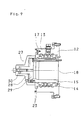
- Fig. 1 shows a hydraulically operated Clamping cylinder 1 for clamping devices Machine tools 2, which has a cylinder housing 3, in its cylinder chamber 4 a cylinder piston 5 axially is adjustable.
- the shown in Fig. 3 isolated Cylinder housing 3 is rotating in FIG. 1 driven work spindle 6 shown attached, wherein after mounting the clamping cylinder 1 by the Fastening the cylinder housing 3 to the work spindle 6 as the first assembly step, concentric and axial run-out tests first test areas 7 are executed, which on Cylinder housing 3 on the Distributor hollow shaft receiving section 8 are formed and run radially and axially. Through this round and Axial runout is the correct attachment of the Checked cylinder housing 3 on the work spindle 6.
- the clamping cylinder 1 also has a Receiving bell 9, which during further assembly on the Machine tool 2 attached and their correct assembly likewise by means of radial and axial run-out tests is checked, which take place on second test surfaces 10, the on the bell 9 on the Distribution housing receiving part 11 radially and axially are progressive.
- the clamping cylinder 1 still has a distributor 12 consisting of a Distributor housing 13 having pressure medium connections 26, a distributor socket 14 and one Pressure medium lines 25 Distributor hollow shaft 15, which for assembly by a particularly evident from FIG. 2 Transport flange 16 in a fixed predetermined relative Alignment are held, namely in a first Position in the between the distributor socket 14 and the Distributor housing 13 a spacer 17 whose relative axial distance determined.
- Transport flange 16 predetermined position is the Distributor hollow shaft 15 on the cylinder housing 3 and that Distribution housing 13 attached to the receiving bell 9.
- the transport flange 16 is then removed and replaced by an end flange 21.
- an adjustment of the Distribution sleeve 14 from the first position to a second Position required.
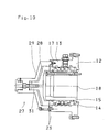
- a Transport flange 16 replacing in exchange Assembly template 27 is provided with one at the Distribution sleeve 14 connectable adjusting sleeve 28 and one on the distributor housing 13 (Fig. 10) or the Distributor hollow shaft 15 (Fig. 9) connectable Reference sleeve 29, the adjusting sleeve 28 compared to the Reference sleeve 29 is adjustable, and that is exactly that for the transfer of the distributor bushing 14 from the first Position in the second position required both measure translational as well as rotary.
- Threaded connection 31 stops for limiting the Has angle of rotation to the required degree and / or the thread of the threaded connection 31 an incline having the required rotation of the Distribution bushing 14 the required feed in parallel to the cylinder axis 18 results.
- the distributor bush 14 In the first position, the distributor bush 14 is also with their inside diameter on the outside diameter of the Distributor hollow shaft 15 centered, which the Distribution housing 13 also with its inner diameter the outer diameter of the distributor bushing 14 centered becomes. This centering remains when the Distributor 12 on the cylinder housing 3 or Receive bell 9 received.
- the adjustment of the distributor bush 14 between the first Position and the second position involves a rotation around the cylinder axis 18 and a shift in the direction the cylinder axis 18, wherein to adjust the Distributor play between the distributor hollow shaft 15 and the Distributor bushing 14 in the circumferential direction via a Subarea in the second position adjoining surfaces formed a groove 19 is, namely in the outer circumference of the distributor hollow shaft 15 (Fig. 5).
- the angle of rotation is that in the drawing 15 ° shown embodiment, but can also in Ranges between 5 ° and 30 °.
- the adjustment of the distributor bushing 14 shows as first step on the rotation after which the Distribution sleeve 14 through an opening the thickness of the Overcome spacer 17 (Fig. 4) and in the second Step can perform the axial displacement that continue to overlap axially Medium guide channels 20 in the distributor bush 14 and the Distributor hollow shaft 15 and the end flange 21st serves.
Landscapes
- Engineering & Computer Science (AREA)
- Mechanical Engineering (AREA)
- Drilling And Boring (AREA)
- Jigs For Machine Tools (AREA)
Abstract
Description
- Fig. 1
- einen Axialschnitt durch einen erfindungsgemäßen Spannzylinder in seiner Arbeitskonfiguration mit dem Abschlußflansch,
- Fig. 2
- den isoliert dargestellen Verteiler, verbunden über den Transportflansch vor der Befestigung an dem Zylinder in einem Axialschnitt,
- Fig. 3
- den Zylinder vor seiner Befestigung an der Arbeitspindel in einem Axialschnitt,
- Fig. 4
- das Detail IV aus Fig. 2,
- Fig. 5
- eine der Fig. 4 entsprechende Darstellung mit dem den Transportflansch ersetzenden Abschlußflansch und der in die zweite Position verstellten Verteilerbuchse,
- Fig. 6
- eine isolierte Darstellung des Abschlußflansches in einem Axialschnitt,
- Fig. 7
- eine Hinteransicht des Spannzylinders,
- Fig. 8
- auf einem Teil des Umfangs der Aufnahmeglocke eine der Stellschrauben, strichliert dargestellt,
- Fig. 9
- eine der Fig. 2 entsprechende Darstellung mit der den Transportflansch ersetzenden Montagelehre, und
- Fig.10
- eine der Fig. 9 entsprechende Darstellung einer weiteren Ausführungsform der Montagelehre.
Claims (24)
- Hydraulisch betätigter Spannzylinder für Spanneinrichtungen an Werkzeugmaschinen (2), mit einem mit der rotierend antreibbaren Arbeitsspindel (6) der Werkzeugmaschine (2) koppelbaren Zylindergehäuse (3) und einem in der Zylinderkammer (4) axial verstellbaren Zylinderkolben (5), sowie mit einem Verteiler (12), der ein feststehendes, die Druckmittelanschlüsse (26) aufweisendes Verteilergehäuse (13) und eine mit dem Zylindergehäuse (3) verbundene, die Druckmittelleitungen (25) aufweisende Verteilerhohlwelle (15) umfaßt, dadurch gekennzeichnet, daß das Verteilergehäuse (13) über eine Aufnahmeglocke (9) an der Werkzeugmaschine (2) befestigt ist, daß der Verteiler (12) eine zwischen dem Verteilergehäuse (13) und der Verteilerhohlwelle (15) angeordnete Verteilerbuchse (14) aufweist, und daß die Verteilerbuchse (14) zwischen einer ersten Position, die der Montage des Verteilers (12) und dessen Zentrierung dient, und einer zweiten Position verstellbar ist, in der das Verteilerspiel für die Mediumübertragung bereitgestellt ist.
- Spannzylinder nach Anspruch 1, dadurch gekennzeichnet, daß die erste Position durch einen an dem Verteilergehäuse (13) und der Verteilerhohlwelle (15) befestigten, dem Tranport und der Montage dienenden Transportflansch (16) vorgegeben ist.
- Spannzylinder nach Anspruch 1 oder 2, dadurch gekennzeichnet, daß in der ersten Position die Verteilerbuchse (14) mit ihrem Innendurchmesser auf dem Außendurchmesser der Verteilerhohlwelle (15) zentriert ist, und daß das Verteilergehäuse (13) mit seinem Innendurchmesser auf dem Außendurchmesser der Verteilerbuchse (14) zentriert ist.
- Spannzylinder nach einem der Ansprüche 1 bis 3, dadurch gekennzeichnet, daß in der zweiten Position durch einen den Transportflansch (16) im Austausch ersetzenden Abschlußflansch (21) gehalten die Verteilerbuchse (14) justiert ist.
- Spannzylinder nach einem der Ansprüche 1 bis 4, dadurch gekennzeichnet, daß die Verstellung der Verteilerbuchse (14) zwischen der ersten Position und der zweiten Position eine Drehung um die Zylinderachse (18) und eine Verschiebung in Richtung der Zylinderachse (18) beinhaltet, und daß zur Einstellung des Verteilerspiels zwischen der Verteilerhohlwelle (15) und der Verteilerbuchse (14) in Umfangsrichtung über einen Teilbereich der in der zweiten Position aneinander grenzenden Flächen eine Kehlung (19) ausgebildet ist.
- Spannzylinder nach Anspruch 5, dadurch gekennzeichnet, daß eine den Transportflansch (16) im Austausch ersetzende Montagelehre (27) vorgesehen ist, mit einer an der Verteilerbuchse (14) anschließbaren Stellhülse (28) sowie einer an dem Verteilergehäuse (13) und/oder der Verteilerhohlwelle (15) anschließbaren Referenzhülse (29), und daß die Stellhülse (28) gegenüber der Referenzhülse (29) verstellbar ist.
- Spannzylinder nach Anspruch 6, dadurch gekennzeichnet, daß die Stellhülse (28) zur ihrer translatorischen Verstellung mit einer in der Referenzhülse (29) gelagerten Verstellspindel (30) gekoppelt ist.
- Spannzylinder nach Anspruch 6, dadurch gekennzeichnet, daß Stellhülse (28) gegenüber der Referenzhülse (29) genau um das für die Überführung der Verteilerbuchse (14) aus der ersten Position in die zweite Position erforderliche Maß sowohl translatorisch als auch rotatorisch verstellbar ist.
- Spannzylinder nach Anspruch 8, dadurch gekennzeichnet, daß zwischen der Stellhülse (28) und der Referenzhülse (29) eine Gewindeverbindung (31) ausgebildet ist.
- Spannzylinder nach Anspruch 9, dadurch gekennzeichnet, daß die Gewindeverbindung (31) Anschläge für die Begrenzung des Drehwinkels auf das erforderliche Maß aufweist.
- Spannzylinder nach Anspruch 9 oder 10, dadurch gekennzeichnet, daß das Gewinde der Gewindeverbindung (31) eine Steigung aufweist, die bei der erforderlichen Drehung der Verteilerbuchse (14) deren erforderlichen Vorschub parallel zur Zylinderachse (18) ergibt.
- Spannzylinder nach einem der Ansprüche 5 bis 11, dadurch gekennzeichnet, daß die Kehlung (19) im Außenumfang der Verteilerhohlwelle (15) ausgebildet ist.
- Spannzylinder nach einem der Ansprüche 5 bis 12, dadurch gekennzeichnet, daß der Drehwinkel 5° bis 30°, vorzugsweise 15° beträgt.
- Spannzylinder nach einem der Ansprüche 1 bis 13, dadurch gekennzeichnet, daß die Verstellung der Verteilerbuchse (14) zwischen der ersten Position und der zweiten Position der axialen Überdeckung von Mediumführungsrinnen (20) in der Verteilerbuchse (14) und der Verteilerhohlwelle (15) dient.
- Spannzylinder nach einem der Ansprüche 2 bis 14, dadurch gekennzeichnet, daß dem Transportflansch (16) eine in der ersten Position der Verteilerbuchse (14) zwischen dieser und dem Verteilergehäuse (13) plazierte Distanzscheibe (17) zugeordnet ist.
- Spannzylinder nach einem der Ansprüche 1 bis 15, dadurch gekennzeichnet, daß in der Aufnahmeglocke (9) gleichmäßig über den Umfang verteilt tangential ausgerichtete Stellschrauben (24) angeordnet sind.
- Spannzylinder nach einem der Ansprüche 1 bis 16, dadurch gekennzeichnet, daß am Zylindergehäuse (3) an der Verteilerhohlwelle-Aufnahmepartie (8) radial und axial verlaufende erste Prüfflächen (7) ausgebildet sind.
- Spannzylinder nach einem der Ansprüche 1 bis 17, dadurch gekennzeichnet, daß an der Aufnahmeglocke (9) an der Zylindergehäuse-Aufnahmepartie (11) radial und axial verlaufende zweite Prüfflächen (10) ausgebildet sind.
- Spannzylinder nach einem der Ansprüche 1 bis 18, dadurch gekennzeichnet, daß am freien Ende der Verteilerhohlwelle (15) radial und axial verlaufende dritte Prüfflächen (22) ausgebildet sind.
- Spannzylinder nach einem der Ansprüche 1 bis 19, dadurch gekennzeichnet, daß am Verteilergehäuse (13) radial und axial verlaufende vierte Prüfflächen (23) ausgebildet sind.
- Verfahren zur Montage eines Spannzylinders nach einem der Ansprüche 1 bis 20, dadurch gekennzeichnet, daß das Zylindergehäuse (3) auf das hintere Ende der Arbeitsspindel (6) befestigt wird, daß an den ersten Prüfflächen (7) des Zylindergehäuses (3) eine Rundund Planlaufprüfung erfolgt, daß die Aufnahmeglocke (9) an der Werkzeugmaschine (2) befestigt wird, daß an den zweiten Prüfflächen (10) der Aufnahmeglocke eine Rund- und Planlaufprüfung erfolgt, daß durch den Transportflansch (16) das Verteilergehäuse (13), die Verteilerbuchse (14) und die Verteilerhohlwelle (15) in die Montagelage gebracht werden, in der sich die Verteilerbuchse (14) in ihrer ersten Position befindet, daß in der durch den Transportflansch (16) vorgegebenen Lage die Verteilerhohlwelle (15) an dem Zylindergehäuse (3) und das Verteilergehäuse (13) an der Aufnahmeglocke (9) befestigt wird, daß der Transportflansch (16) entfernt wird, daß die Verteilerbuchse (14) in ihre zweite Position verstellt und dort durch den Abschlußflansch (21) gehalten wird, daß an den dritten Prüfflächen (22) der Verteilerhohlwelle (15) eine Rund- und Planlaufprüfung erfolgt, und daß an den vierten Prüfflächen (23) des Verteilergehäuses (13) eine Rund- und Planlaufprüfung erfolgt.
- Verfahren nach Anspruch 21, dadurch gekennzeichnet, daß zur Verstellung der Verteilerbuchse (14) aus der ersten Position in die zweite Position nach der Entfernung des Transportflansches (16) die
Stellhülse (28) mit der Verteilerbuchse (14) und die Referenzhülse (29) mit dem Verteilergehäuse (13) drehfest verbunden und die Stellhülse (28) verstellt wird. - Verfahren nach Anspruch 21, dadurch gekennzeichnet, daß zur Verstellung der Verteilerbuchse (14) aus der ersten Position in die zweite Position nach der Entfernung des Transportflansches (16) die
Stellhülse (28) mit der Verteilerbuchse (14) und die Referenzhülse (29) mit der Verteilerhohlwelle (15) drehfest verbunden und die Stellhülse (28) verstellt wird. - Verfahren nach Anspruch 21, dadurch gekennzeichnet, daß eine radiale Feineinstellung des Verteilergehäuses (13) mit den Stellschrauben (24) erfolgt.
Applications Claiming Priority (2)
| Application Number | Priority Date | Filing Date | Title |
|---|---|---|---|
| DE10139718 | 2001-08-13 | ||
| DE2001139718 DE10139718A1 (de) | 2001-08-13 | 2001-08-13 | Hydraulisch betätigter Spannzylinder sowie Verfahren zur Montage eines Spannzylinders |
Publications (1)
| Publication Number | Publication Date |
|---|---|
| EP1285712A1 true EP1285712A1 (de) | 2003-02-26 |
Family
ID=7695299
Family Applications (1)
| Application Number | Title | Priority Date | Filing Date |
|---|---|---|---|
| EP02007965A Withdrawn EP1285712A1 (de) | 2001-08-13 | 2002-04-10 | Hydraulisch betätigter Spannzylinder sowie Verfahren zur Montage eines Spannzylinders |
Country Status (2)
| Country | Link |
|---|---|
| EP (1) | EP1285712A1 (de) |
| DE (1) | DE10139718A1 (de) |
Citations (2)
| Publication number | Priority date | Publication date | Assignee | Title |
|---|---|---|---|---|
| US5106244A (en) * | 1989-10-26 | 1992-04-21 | Fujii Seimitsu Kogyo Co., Ltd. | Air operated chuck |
| DE19823823A1 (de) * | 1998-05-28 | 1999-12-09 | Roehm Gmbh | Spannzylinder mit Kühlungsöffnungen |
-
2001
- 2001-08-13 DE DE2001139718 patent/DE10139718A1/de not_active Withdrawn
-
2002
- 2002-04-10 EP EP02007965A patent/EP1285712A1/de not_active Withdrawn
Patent Citations (2)
| Publication number | Priority date | Publication date | Assignee | Title |
|---|---|---|---|---|
| US5106244A (en) * | 1989-10-26 | 1992-04-21 | Fujii Seimitsu Kogyo Co., Ltd. | Air operated chuck |
| DE19823823A1 (de) * | 1998-05-28 | 1999-12-09 | Roehm Gmbh | Spannzylinder mit Kühlungsöffnungen |
Also Published As
| Publication number | Publication date |
|---|---|
| DE10139718A1 (de) | 2003-03-06 |
Similar Documents
| Publication | Publication Date | Title |
|---|---|---|
| DE19940330A1 (de) | Werkzeugspanneinrichtung | |
| DE3700430C2 (de) | Kugelumlaufspindel-Mutter | |
| DE4409603A1 (de) | Vorrichtung zum Einspannen eines Werkzeugs oder eines Werkstücks | |
| WO2006010607A1 (de) | Wuchtring und verfahren zum auswuchten eines rotierenden bauteils | |
| DE2836395C2 (de) | Satzfräser | |
| EP0164582B1 (de) | Spannelement zum zentrischen Spannen rotierender Teile | |
| EP0719640B1 (de) | Zylinder einer Rotationsdruckmaschine | |
| EP2463538A1 (de) | Schrumpfscheibe zur reibschlüssigen Verbindung von rotierenden Maschinenteilen | |
| DE2134221A1 (de) | Einstellbare Zentriervorrichtung | |
| EP3815822A1 (de) | Hydrodehnspannfutter | |
| EP0870972A2 (de) | Zweiteiliges Gehäuse und Verfahren zu seiner Fertigung | |
| DE69225616T2 (de) | Maschinenspindel oder werkzeughalter mit einem integrierten futter und methode zum herstellen desselben | |
| DE10139718A1 (de) | Hydraulisch betätigter Spannzylinder sowie Verfahren zur Montage eines Spannzylinders | |
| DE3223748C2 (de) | ||
| DE10117990C1 (de) | Vorrichtung zur hochgenauen Bearbeitung von Zylinderlaufflächen | |
| DE10147581C1 (de) | Spannfutter | |
| DE3805527A1 (de) | Werkzeugwechselsystem | |
| EP1334283B1 (de) | Gleitgelagerte, geschweisste baueinheit | |
| DE3433492A1 (de) | Mehrspindelkopf | |
| DE69509364T2 (de) | Radial arretierte vorrichtung für scheibe und spindel | |
| WO2003095132A1 (de) | Dehnspanneinrichtung | |
| DE3931737A1 (de) | Eigenantriebsspindel | |
| DE10219525A1 (de) | Hydraulisch betätigter Spannzylinder sowie Verfahren zur Montage eines Spannzylinders | |
| DE19641865A1 (de) | Axialkolbenmaschine mit Haltevorrichtung für die Zylindertrommel | |
| DE3433696C2 (de) |
Legal Events
| Date | Code | Title | Description |
|---|---|---|---|
| PUAI | Public reference made under article 153(3) epc to a published international application that has entered the european phase |
Free format text: ORIGINAL CODE: 0009012 |
|
| AK | Designated contracting states |
Kind code of ref document: A1 Designated state(s): AT BE CH CY DE DK ES FI FR GB GR IE IT LI LU MC NL PT SE TR Designated state(s): AT BE CH CY DE DK ES FI FR GB GR IE IT LI LU MC NL PT SE TR |
|
| AX | Request for extension of the european patent |
Extension state: AL LT LV MK RO SI |
|
| 17P | Request for examination filed |
Effective date: 20030219 |
|
| GRAH | Despatch of communication of intention to grant a patent |
Free format text: ORIGINAL CODE: EPIDOS IGRA |
|
| AKX | Designation fees paid |
Designated state(s): AT ES FR GB IT TR |
|
| REG | Reference to a national code |
Ref country code: DE Ref legal event code: 8566 |
|
| STAA | Information on the status of an ep patent application or granted ep patent |
Free format text: STATUS: THE APPLICATION IS DEEMED TO BE WITHDRAWN |
|
| 18D | Application deemed to be withdrawn |
Effective date: 20031105 |