EP1284343B1 - Cooling system for a motor vehicle and related motor vehicle - Google Patents
Cooling system for a motor vehicle and related motor vehicle Download PDFInfo
- Publication number
- EP1284343B1 EP1284343B1 EP02018312A EP02018312A EP1284343B1 EP 1284343 B1 EP1284343 B1 EP 1284343B1 EP 02018312 A EP02018312 A EP 02018312A EP 02018312 A EP02018312 A EP 02018312A EP 1284343 B1 EP1284343 B1 EP 1284343B1
- Authority
- EP
- European Patent Office
- Prior art keywords
- cooler
- cooling system
- cooling
- air
- coolant
- Prior art date
- Legal status (The legal status is an assumption and is not a legal conclusion. Google has not performed a legal analysis and makes no representation as to the accuracy of the status listed.)
- Expired - Fee Related
Links
Images


Classifications
-
- F—MECHANICAL ENGINEERING; LIGHTING; HEATING; WEAPONS; BLASTING
- F28—HEAT EXCHANGE IN GENERAL
- F28D—HEAT-EXCHANGE APPARATUS, NOT PROVIDED FOR IN ANOTHER SUBCLASS, IN WHICH THE HEAT-EXCHANGE MEDIA DO NOT COME INTO DIRECT CONTACT
- F28D1/00—Heat-exchange apparatus having stationary conduit assemblies for one heat-exchange medium only, the media being in contact with different sides of the conduit wall, in which the other heat-exchange medium is a large body of fluid, e.g. domestic or motor car radiators
- F28D1/02—Heat-exchange apparatus having stationary conduit assemblies for one heat-exchange medium only, the media being in contact with different sides of the conduit wall, in which the other heat-exchange medium is a large body of fluid, e.g. domestic or motor car radiators with heat-exchange conduits immersed in the body of fluid
- F28D1/04—Heat-exchange apparatus having stationary conduit assemblies for one heat-exchange medium only, the media being in contact with different sides of the conduit wall, in which the other heat-exchange medium is a large body of fluid, e.g. domestic or motor car radiators with heat-exchange conduits immersed in the body of fluid with tubular conduits
- F28D1/0408—Multi-circuit heat exchangers, e.g. integrating different heat exchange sections in the same unit or heat exchangers for more than two fluids
- F28D1/0426—Multi-circuit heat exchangers, e.g. integrating different heat exchange sections in the same unit or heat exchangers for more than two fluids with units having particular arrangement relative to the large body of fluid, e.g. with interleaved units or with adjacent heat exchange units in common air flow or with units extending at an angle to each other or with units arranged around a central element
-
- F—MECHANICAL ENGINEERING; LIGHTING; HEATING; WEAPONS; BLASTING
- F01—MACHINES OR ENGINES IN GENERAL; ENGINE PLANTS IN GENERAL; STEAM ENGINES
- F01P—COOLING OF MACHINES OR ENGINES IN GENERAL; COOLING OF INTERNAL-COMBUSTION ENGINES
- F01P5/00—Pumping cooling-air or liquid coolants
- F01P5/02—Pumping cooling-air; Arrangements of cooling-air pumps, e.g. fans or blowers
-
- F—MECHANICAL ENGINEERING; LIGHTING; HEATING; WEAPONS; BLASTING
- F02—COMBUSTION ENGINES; HOT-GAS OR COMBUSTION-PRODUCT ENGINE PLANTS
- F02B—INTERNAL-COMBUSTION PISTON ENGINES; COMBUSTION ENGINES IN GENERAL
- F02B29/00—Engines characterised by provision for charging or scavenging not provided for in groups F02B25/00, F02B27/00 or F02B33/00 - F02B39/00; Details thereof
- F02B29/04—Cooling of air intake supply
- F02B29/0406—Layout of the intake air cooling or coolant circuit
- F02B29/0425—Air cooled heat exchangers
- F02B29/0431—Details or means to guide the ambient air to the heat exchanger, e.g. having a fan, flaps, a bypass or a special location in the engine compartment
-
- F—MECHANICAL ENGINEERING; LIGHTING; HEATING; WEAPONS; BLASTING
- F04—POSITIVE - DISPLACEMENT MACHINES FOR LIQUIDS; PUMPS FOR LIQUIDS OR ELASTIC FLUIDS
- F04D—NON-POSITIVE-DISPLACEMENT PUMPS
- F04D29/00—Details, component parts, or accessories
- F04D29/40—Casings; Connections of working fluid
- F04D29/42—Casings; Connections of working fluid for radial or helico-centrifugal pumps
- F04D29/4206—Casings; Connections of working fluid for radial or helico-centrifugal pumps especially adapted for elastic fluid pumps
- F04D29/4226—Fan casings
- F04D29/4246—Fan casings comprising more than one outlet
-
- F—MECHANICAL ENGINEERING; LIGHTING; HEATING; WEAPONS; BLASTING
- F01—MACHINES OR ENGINES IN GENERAL; ENGINE PLANTS IN GENERAL; STEAM ENGINES
- F01P—COOLING OF MACHINES OR ENGINES IN GENERAL; COOLING OF INTERNAL-COMBUSTION ENGINES
- F01P3/00—Liquid cooling
- F01P3/18—Arrangements or mounting of liquid-to-air heat-exchangers
- F01P2003/182—Arrangements or mounting of liquid-to-air heat-exchangers with multiple heat-exchangers
-
- F—MECHANICAL ENGINEERING; LIGHTING; HEATING; WEAPONS; BLASTING
- F01—MACHINES OR ENGINES IN GENERAL; ENGINE PLANTS IN GENERAL; STEAM ENGINES
- F01P—COOLING OF MACHINES OR ENGINES IN GENERAL; COOLING OF INTERNAL-COMBUSTION ENGINES
- F01P3/00—Liquid cooling
- F01P3/18—Arrangements or mounting of liquid-to-air heat-exchangers
- F01P2003/185—Arrangements or mounting of liquid-to-air heat-exchangers arranged in parallel
-
- F—MECHANICAL ENGINEERING; LIGHTING; HEATING; WEAPONS; BLASTING
- F01—MACHINES OR ENGINES IN GENERAL; ENGINE PLANTS IN GENERAL; STEAM ENGINES
- F01P—COOLING OF MACHINES OR ENGINES IN GENERAL; COOLING OF INTERNAL-COMBUSTION ENGINES
- F01P3/00—Liquid cooling
- F01P3/18—Arrangements or mounting of liquid-to-air heat-exchangers
- F01P2003/187—Arrangements or mounting of liquid-to-air heat-exchangers arranged in series
-
- F—MECHANICAL ENGINEERING; LIGHTING; HEATING; WEAPONS; BLASTING
- F01—MACHINES OR ENGINES IN GENERAL; ENGINE PLANTS IN GENERAL; STEAM ENGINES
- F01P—COOLING OF MACHINES OR ENGINES IN GENERAL; COOLING OF INTERNAL-COMBUSTION ENGINES
- F01P2060/00—Cooling circuits using auxiliaries
- F01P2060/02—Intercooler
-
- F—MECHANICAL ENGINEERING; LIGHTING; HEATING; WEAPONS; BLASTING
- F01—MACHINES OR ENGINES IN GENERAL; ENGINE PLANTS IN GENERAL; STEAM ENGINES
- F01P—COOLING OF MACHINES OR ENGINES IN GENERAL; COOLING OF INTERNAL-COMBUSTION ENGINES
- F01P2060/00—Cooling circuits using auxiliaries
- F01P2060/04—Lubricant cooler
-
- F—MECHANICAL ENGINEERING; LIGHTING; HEATING; WEAPONS; BLASTING
- F01—MACHINES OR ENGINES IN GENERAL; ENGINE PLANTS IN GENERAL; STEAM ENGINES
- F01P—COOLING OF MACHINES OR ENGINES IN GENERAL; COOLING OF INTERNAL-COMBUSTION ENGINES
- F01P2060/00—Cooling circuits using auxiliaries
- F01P2060/14—Condenser
-
- F—MECHANICAL ENGINEERING; LIGHTING; HEATING; WEAPONS; BLASTING
- F02—COMBUSTION ENGINES; HOT-GAS OR COMBUSTION-PRODUCT ENGINE PLANTS
- F02B—INTERNAL-COMBUSTION PISTON ENGINES; COMBUSTION ENGINES IN GENERAL
- F02B29/00—Engines characterised by provision for charging or scavenging not provided for in groups F02B25/00, F02B27/00 or F02B33/00 - F02B39/00; Details thereof
- F02B29/04—Cooling of air intake supply
- F02B29/045—Constructional details of the heat exchangers, e.g. pipes, plates, ribs, insulation, materials, or manufacturing and assembly
- F02B29/0475—Constructional details of the heat exchangers, e.g. pipes, plates, ribs, insulation, materials, or manufacturing and assembly the intake air cooler being combined with another device, e.g. heater, valve, compressor, filter or EGR cooler, or being assembled on a special engine location
-
- Y—GENERAL TAGGING OF NEW TECHNOLOGICAL DEVELOPMENTS; GENERAL TAGGING OF CROSS-SECTIONAL TECHNOLOGIES SPANNING OVER SEVERAL SECTIONS OF THE IPC; TECHNICAL SUBJECTS COVERED BY FORMER USPC CROSS-REFERENCE ART COLLECTIONS [XRACs] AND DIGESTS
- Y02—TECHNOLOGIES OR APPLICATIONS FOR MITIGATION OR ADAPTATION AGAINST CLIMATE CHANGE
- Y02T—CLIMATE CHANGE MITIGATION TECHNOLOGIES RELATED TO TRANSPORTATION
- Y02T10/00—Road transport of goods or passengers
- Y02T10/10—Internal combustion engine [ICE] based vehicles
- Y02T10/12—Improving ICE efficiencies
Definitions
- the invention relates to a motor vehicle Kohlsystem an internal combustion engine according to the preamble of claim 1. Furthermore, the invention relates to a motor vehicle with a corresponding cooling system.
- Motor vehicle cooling systems of the type mentioned are already known. They often include an axial fan, which is provided to achieve a desired cooling air penetration of a charge air cooler and a coolant radiator.
- the charge air supplied by a turbocharger is cooled in the intercooler and then passed into an internal combustion engine, such as a turbo diesel engine.
- an internal combustion engine such as a turbo diesel engine.
- coolant radiator coolant supplied by the internal combustion engine is cooled and then returned to the internal combustion engine, preferably to form a closed coolant circuit.
- the axial fan is seen interposed in the cooling air flow direction behind the series-arranged units and in front of the engine.
- the cooling air is sucked in such a way that it usually passes through the intercooler, then passed through the coolant radiator and finally on the pressure side of the axial fan at least partially in the direction of the motor housing (engine block of the engine) flows.
- the cooling units (intercooler, coolant radiator) are thus in Seen cooling air flow direction arranged one behind the other and usually designed as a cross-flow cooler.
- these refrigeration units are arranged in front of the motor housing front side of the corresponding motor vehicle -with the interposition of the axial fan and thus, as a rule, also on the vehicle front.
- a fan for a motor vehicle cooling system which is designed as a radial fan and associated with a coolant radiator of an internal combustion engine.
- the radial fan also has a designed as a spiral housing air duct housing.
- a motor vehicle cooling system with the features of claim 1 is proposed, which is characterized in that at least one additional radiator designed as a countercurrent intercooler, and that the radial fan frontal of the internal combustion engine of the motor vehicle and the coolant radiator and the intercooler are arranged on a respective lateral side of the internal combustion engine, wherein the radial fan by means of a respective outlet channel with the coolant radiator and the intercooler is connected.
- Radial fans are characterized by a relatively good static efficiency of 70% to 75%, while the efficiency of good axial fans is only 45% to 50%. While axial fans are usually operated at a relatively low operating pressure and high volume flow, radial fans operate at relatively high operating pressures and lower volume flows.
- the radial fan allows due to the (streamlined) radial deflection of selbiges passing cooling air structurally adapted to the particular design of the engine or the motor vehicle spatial arrangement of the respective units of the cooling system.
- an arrangement of all refrigeration units for example, coolant radiator, intercooler
- the radial fan with spiral housing is characterized by a particularly favorable efficiency while allowing the achievement of the advantages mentioned above.
- Designed as a counterflow cooler intercooler is characterized by a better use of cooling air in comparison to a cross-flow cooler.
- the cooling air requirement is relatively low due to the good use of cooling air in the countercurrent principle.
- the frontally mounted in front of the internal combustion engine of a motor vehicle radial fan allows a relatively flexible and structurally simple design spatial arrangement of the other units of the cooling system in an engine compartment.
- the outlet channels are preferably designed as streamlined cooling air lines.
- a flexible adaptation of the cooling unit assembly in the motor vehicle to the respective available installation space is possible, while ensuring relatively low fan drive performance.
- a relatively small frontal installation volume in the engine compartment of the motor vehicle is occupied by the cooling system by means of such an arrangement of the cooling units, so that more space for a particular more powerful combustion engine in the engine compartment is available while ensuring an effective cooling system.
- the radially exiting radially from the centrifugal fan cooling air streams can be performed in each strömungs protester way to the cooling units.
- At least one cooler may additionally be an oil cooler, a condenser of an air conditioning system and / or another cooling unit (for example an exhaust gas recirculation cooler).
- the intercooler can be designed, for example, as a charge air / air cooler or as a charge air / coolant radiator.
- the coolant radiator may be a high-temperature or a low-temperature radiator.
- the radial fan may have a single cooling air outlet to which a suitable for differentiatedde Kunststoffbeetzung trained and connected to the units cooling air duct system is connected, or it may also have multiple cooling air outlets on the radial fan be provided, which are associated with a respective associated unit. Any necessary cooling air distribution can be achieved in a conventional manner by using suitable functional elements, such as valves, valves, sliders, or the like.
- At least two coolers are connected to each other in series with the interposition of the radial fan.
- at least two coolers can be connected in parallel with each other.
- the use of a radial fan allows an advantageous variety of possible arrangements of optionally different types of coolers.
- at least one cooler in particular a coolant radiator, can be arranged on the outlet side of the radial fan.
- the coolant radiator and the intercooler are connected in parallel to one another on the outlet side of the radial fan. Since the cooling units can be arranged on the outlet side of the radial fan and not in front of the fan as in the conventional cooling system, a relatively cold cooling air flow is sucked in by means of the radial fan.
- a radial fan is particularly suitable for streamlined distribution of selbiges passing cooling air flow into two partial cooling air streams for the separate admission of parallel to each other on the outlet side of the centrifugal fan arranged cooling units (coolant radiator, intercooler). Due to the parallel arrangement of the two cooling units both are acted upon independently of each other with relatively cold or not preheated cooling air.
- the coolant cooler can be designed as a countercurrent condenser, as a crossflow condenser or as a cross countercurrent condenser. Due to the flexibly configurable cooling air flow guide, a flow-friendly and thus also low-efficiency connection of the radial fan can be realized with variously designed cooling units. Also, the charge air cooler may be formed as a cross-countercurrent cooler.
- the radial fan is advantageously in drive connection with the internal combustion engine.
- a conventional cooling system with axial fan up to 10% of the engine power for example, a turbo diesel engine of a truck to operate the cooling system is consumed.
- a low-efficiency cooling system with radial fan significantly less engine power of the engine which is in line with the tendency of a use of more powerful internal combustion engines in motor vehicles. It is thus in radial fans compared to axial fans to provide a lower fan drive performance due to the better fan efficiency, to achieve a certain cooling capacity in the cooling system according to the invention also a smaller amount of air through the fan enforce, resulting in a higher available engine power of the engine and lower fuel consumption of the motor vehicle leads.
- the radial fan can be driven for example by means of a crankshaft of the internal combustion engine, optionally with the interposition of a gear transmission or a belt drive (high-lift). Alternatively, in this regard, a separate electric motor or a Hydrostatantrieb be provided.
- the charge air cooler is connected at its charge air inlet side in particular by means of a charge air line with a charge air turbocharger and is at its charge air outlet side in particular by means of a charge air line to the engine in connection.
- a charge air turbocharger is connected at its charge air inlet side in particular by means of a charge air line with a charge air turbocharger and is at its charge air outlet side in particular by means of a charge air line to the engine in connection.
- the charge air ducts do not lead, as in conventional cooling systems, to a charge air cooler arranged frontally with respect to the internal combustion engine, but because of the use of a radial fan, the charge air cooler can now be arranged at a structurally more favorable (overall efficiency-favorable) position in the engine compartment with an advantageous design of relatively short charge air ducts (lower pressure loss) and with a corresponding reduction in the charge air supply power to be applied. Furthermore, this allows an improved engine response dynamics can be achieved.
- the cooling medium of the charge air cooler and the coolant radiator cooling air which is supplied through a respective cooling air line to the coolant radiator and the intercooler.
- the cooling air ducts are designed in particular streamlined, so that the power losses to the cooling air supply from the radial fan in the cooling units as low as possible.
- Cooling air ducts for cooling air discharge are advantageously provided on the cooling air outlet side on the coolant radiator and / or on the intercooler.
- the cooling air exiting the cooling system is not guided against the engine block of the internal combustion engine, as is the case with the use of axial fans in conventional motor vehicle cooling systems, but can be directed to reduced flow in the engine compartment reduction of cooling power in principle undesirable power dissipation in the engine compartment ,
- the internal combustion engine may be a supercharged gasoline engine or a diesel engine, in particular a turbo diesel engine, a truck or a passenger car.
- FIG. 1 1 shows a block diagram of a motor vehicle cooling system 10.
- the cooling system or cooling arrangement 10 includes a fan 12, which is designed as a radial fan and is in drive connection with an internal combustion engine 24 by means of a shaft 40, that is, the radial fan 12 is driven by the internal combustion engine 24.
- the radial fan 12 sucks along an intake direction according to arrow 11 cooling air axially and divides them into two radially exiting cooling air streams, a first partial cooling air flow through a cooling air line (arrow 20) a first radiator 13, in the present embodiment, a coolant radiator 14, and the second cooling air partial flow through a further cooling air line (arrow 22) in a second cooler 13, according to the present example in a charge air cooler 16 is passed.
- the coolant radiator 14 is part of a closed coolant circuit, according to which coolant from the engine 24 through a coolant line (arrow 34) is guided into the coolant radiator 14 which is simultaneously acted upon by means of the radial fan 12 according to arrow 20 with cooling air, which passes through the coolant radiator 14 and from selbigem optionally by means of a cooling air line (arrow 38) is discharged.
- the coolant cooled in this way is conducted from the coolant cooler 14 back through a coolant line according to arrow 36 back into the internal combustion engine 24.
- the intercooler 16 is charged by means of a charge air turbocharger 28 and by a charge air line (arrow 26) with charge air.
- the charge air is cooled by supplied from the centrifugal fan 12 through the cooling air line according to arrow 22 cooling air in the intercooler 16 and then passed through a charge air line (arrow 30) in the engine 24.
- the intercooler 16 passing through the cooling air is preferably discharged through a cooling air line according to arrow 32.
- the intercooler 16 is designed as a countercurrent condenser, optionally in the form of a cross-countercurrent condenser.
- the coolant cooler 14 can be designed as a countercurrent cooler, as a crossflow cooler or as a cross counterflow cooler be.
- the coolant cooler 14 and the intercooler 16 are arranged parallel to each other on the outlet side of the radial fan 12.
- the radial fan 12 are arranged frontally in front of the internal combustion engine 24 (engine block) and the coolant cooler 14 and the charge air cooler 16 on a respective lateral side of the internal combustion engine 24.
- a further radiator 13 with respect to the fan 12 in the axial direction can be arranged frontally before selbigem (dashed lines illustrated fan 15).
- the internal combustion engine 24 is preferably a diesel engine, in particular a turbo diesel engine, a truck or a passenger car.
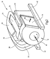
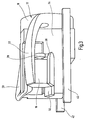
- FIGS. 2 to 4 show schematic views of a motor vehicle cooling system 10 according to the invention according to the block diagram of FIG. 1 ,
- the radial fan 12 is provided with an air guide housing 18 which is formed in this embodiment as a spiral housing.
- the coolant radiator 14 connected to the radial fan 12 is designed as a cross-flow radiator, from which, according to arrow 38, cooling air-without the use of a same-discharging cooling air duct-exits freely into the lateral engine compartment (free space) of the motor vehicle.
- the charge air line 30 connects to supply the cooled charge air in the internal combustion engine 24, the charge air cooler 16 with an air distributor 31 of the engine 24.
- the cooling air lines 20, 22 and the charge air lines 26, 30 are particularly streamlined (relatively low flow resistance) is formed.
- the internal combustion engine 24 engine block
- the further structural design and the operation of the motor vehicle cooling system 10 of FIGS. 2 to 4 correspond to those of FIG. 1 , wherein the cooling air line 32 (cooling air discharge from the intercooler 16) in the FIGS. 3 to 4 is hinted at.
- FIG. 5 shows a schematic representation of a designed as a countercurrent charge air cooler 16.
- the cooling air is supplied, for example, at about 25 ° C as shown in arrow 44 to the intercooler 16 (cooling air passage plane 52), in which the same interspersed charge air (arrows 48, 50, charge air passage plane 54) cooled in such a way that will be the cooling air according to arrow 46 leaves the intercooler 16 at a temperature, for example, of about 200 ° C.
- charge air usually has an operating temperature of up to 260 ° C and is cooled by cooling by the cooling air (arrows 44, 46) to an operating temperature of about 40 ° C, with which the charge air the Air distributor 31 and thus the internal combustion engine 24 is supplied.
- Trained as a countercurrent charge air cooler 16 is particularly advantageous because-in contrast to pure cross-flow coolers- the cooling air can be heated to near the inlet temperature of the charge air, whereby a fundamentally desirable good utilization of the heat absorption capacity of the cooling air is guaranteed.
- the intercooler 16 of the FIG. 5 optionally also be designed as a cross-countercurrent condenser.
- FIG. 6 is a the charge air cooler 16 accordingly FIG.
- FIGS. 6, 7 ribs 58, 56 are shown in the respective enforcement planes 54, 52.
Description
Die Erfindung betrifft ein Krafifahrzeug-Kohlsystem eines Verbrennungsmotors gemäß Oberbegriff des Anspruchs 1. Ferner betrifft die Erfindung ein Kraftfahrzeug mit einem entsprechenden Kühlsystem.The invention relates to a motor vehicle Kohlsystem an internal combustion engine according to the preamble of claim 1. Furthermore, the invention relates to a motor vehicle with a corresponding cooling system.
Kraftfahrzeug-Kühlsysteme der eingangs genannten Art sind bereits bekannt. Sie enthalten häufig einen Axiallüfter, der zur Erzielung einer gewünschten Kühlluftdurchsetzung eines Ladeluftkühlers und eines Kühlmittelkühlers vorgesehen ist. Dabei wird von einem Turbolader zugeführte Ladeluft im Ladeluftkühler gekühlt und anschließend in einen Verbrennungsmotor, beispielsweise einen Turbodieselmotor, geleitet. Im Kühlmittelkühler wird vom Verbrennungsmotor zugeführtes Kühlmittel gekühlt und anschließend in den Verbrennungsmotor rückgeführt, vorzugsweise unter Ausbildung eines geschlossenen Kühlmittelkreislaufs. Sowohl die Ladeluft- als auch die Kühlmittelkühlung erfolgt mittels Kühlluftdurchsetzung der entsprechenden Kühlaggregate (Ladeluftkühler, Kühlmittelkühler), wobei der Axiallüfter in Kühlluftströmungsrichtung gesehen hinter den in Reihe angeordneten Aggregaten und vor dem Verbrennungsmotor zwischengeschaltet ist. Dabei wird mittels des Axiallüfters die Kühlluft derart angesaugt, dass sie in der Regel zunächst den Ladeluftkühler durchsetzt, anschließend durch den Kühlmittelkühler geleitet wird und schließlich auf der Druckseite des Axiallüfters wenigstens teilweise in Richtung Motorgehäuse (Motorblock des Verbrennungsmotors) abströmt. Die Kühlaggregate (Ladeluftkühler, Kühlmittelkühler) sind somit in Kühlluftströmungsrichtung gesehen hintereinander angeordnet und in der Regel als Kreuzstromkühler ausgebildet. Darüber hinaus sind diese Kühlaggregate vor der Motorgehäusefrontseite des entsprechenden Kraftfahrzeugs -unter Zwischenschaltung des Axiallüfters- und somit in der Regel auch an der Fahrzeugfrontseite angeordnet.Motor vehicle cooling systems of the type mentioned are already known. They often include an axial fan, which is provided to achieve a desired cooling air penetration of a charge air cooler and a coolant radiator. In this case, the charge air supplied by a turbocharger is cooled in the intercooler and then passed into an internal combustion engine, such as a turbo diesel engine. In the coolant radiator, coolant supplied by the internal combustion engine is cooled and then returned to the internal combustion engine, preferably to form a closed coolant circuit. Both the charge air and the coolant cooling by means of Kühlluftdurchsetzung the corresponding cooling units (intercooler, coolant radiator), the axial fan is seen interposed in the cooling air flow direction behind the series-arranged units and in front of the engine. In this case, by means of the axial fan, the cooling air is sucked in such a way that it usually passes through the intercooler, then passed through the coolant radiator and finally on the pressure side of the axial fan at least partially in the direction of the motor housing (engine block of the engine) flows. The cooling units (intercooler, coolant radiator) are thus in Seen cooling air flow direction arranged one behind the other and usually designed as a cross-flow cooler. In addition, these refrigeration units are arranged in front of the motor housing front side of the corresponding motor vehicle -with the interposition of the axial fan and thus, as a rule, also on the vehicle front.
Da die Leistungsanforderungen an Verbrennungsmotoren sowohl von Personenkraftwagen als auch von Lastkraftwagen ständig steigen, ist auch ein entsprechend leistungsfähigeres Kühlsystem im Kraftfahrzeug vorzusehen. Dabei ist gleichzeitig zu berücksichtigen, dass der Bauraumbedarf eines leistungszusteigemden Kühlsystems nicht beliebig erweitert werden kann, sondern eher in Abhängigkeit der jeweiligen Verbrennungsmotorausbildung konstruktiven Raumbeschränkungen unterliegt. Die bekannten Kraftfahrzeug-Kühlsysteme sind nachteilig, da sie einen nicht zufriedenstellenden Wirkungsgrad aufweisen und/oder nicht im zur Verfügung stehenden beziehungsweise vorgesehenen Kraftfahrzeug-Bauraum einbaubar sind unter gleichzeitiger Erfüllung der erforderlichen Kühlleistungen.Since the performance requirements of internal combustion engines of both passenger cars and lorries are constantly increasing, a correspondingly more efficient cooling system in the motor vehicle is also to be provided. It should also be considered that the space requirements of a Leistungszusteigemden cooling system can not be arbitrarily extended, but rather subject to constructive space limitations depending on the particular engine training. The known motor vehicle cooling systems are disadvantageous because they have an unsatisfactory efficiency and / or can not be installed in the available or intended motor vehicle installation space while simultaneously fulfilling the required cooling capacities.
Aus der
Es ist Aufgabe der Erfindung, ein Kraftfahrzeug-Kühlsystem der eingangs genannten Art zu schaffen, das sich durch einen im Vergleich zu konventionellen Kühlsystemen verbesserten Wirkungsgrad auszeichnet und gleichzeitig flexibel an konstruktive und kraftfahrzeugspezifische Einbauvorgaben anpassbar ist.It is an object of the invention to provide a motor vehicle cooling system of the type mentioned above, which is characterized by an improved efficiency compared to conventional cooling systems and at the same time flexibly adaptable to constructive and motor vehicle-specific installation specifications.
Zur Lösung der Aufgabe wird ein Kraftfahrzeug-Kühlsystem mit den Merkmalen des Anspruchs 1 vorgeschlagen, das sich dadurch auszeichnet, dass mindestens ein zusätzlicher Kühler ein als Gegenstromkühler ausgebildeter Ladeluftkühler ist, und dass der Radiallüfter frontal vor dem Verbrennungsmotor des Kraftfahrzeugs und der Kühlmittelkühler und der Ladeluftkühler an einer jeweiligen lateralen Seite des Verbrennungsmotors angeordnet sind, wobei der Radiallüfter mittels eines jeweiligen Austrittskanals mit dem Kühlmittelkühler und dem Ladeluftkühler verbunden ist. Radiallüfter zeichnen sich durch einen verhältnismäßig guten statischen Wirkungsgrad von 70 % bis 75 % aus, während der Wirkungsgrad von guten Axiallüftern lediglich 45 % bis 50 % beträgt. Während Axiallüfter üblicherweise bei einem verhältnismäßig niedrigen Betriebsdruck und hohem Volumenstrom betrieben werden, arbeiten Radiallüfter bei relativ hohen Betriebsdrücken und niedrigeren Volumenströmen. Ferner erlaubt der Radiallüfter aufgrund der (strömungsgünstigen) radialen Umlenkung der selbigen durchsetzenden Kühlluft eine konstruktiv an die jeweilige Ausbildung des Verbrennungsmotors beziehungsweise des Kraftfahrzeugs angepasste räumliche Anordnung der jeweiligen Aggregate des Kühlsystems. Im Gegensatz hierzu ist bei einem Axiallüfter eine Anordnung aller Kühlaggregate (beispielsweise Kühlmittelkühler, Ladeluftkühler) im Wesentlichen entlang einer Achse (Ansaugrichtung des Axiallüfters) vorgesehen. Der Radiallüfter mit Spiralgehäuse zeichnet sich durch einen besonders günstigen Wirkungsgrad aus und erlaubt gleichzeitig die Erzielung der oben erwähnten Vorteile. Der als Gegenstromkühler ausgebildeter Ladeluftkühler zeichnet sich durch eine bessere Kühlluftnutzung aus im Vergleich zu einem Kreuzstromkühler. Dabei ist der Kühlluftmengenbedarf aufgrund der guten Kühlluftausnutzung beim Gegenstromprinzip relativ gering. Der frontal vor dem Verbrennungsmotor eines Kraftfahrzeugs angeordnete Radiallüfter ermöglicht eine verhältnismäßig flexible und konstruktiv retativ einfache räumliche Anordnung der weiteren Aggregate des Kühlsystems in einem Motorraum. Die Austrittskanäle sind vorzugsweise als strömungsgünstige Kühlluftleitungen ausgebildet. Hierdurch wird eine flexible Anpassung der Kühlaggregatanordnung im Kraftfahrzeug an den jeweils zur Verfügung stehenden Einbauraum möglich, bei gleichzeitiger Gewährleistung relativ geringer Lüfterantriebsleistungen. Ferner wird mittels einer derartigen Anordnung der Kühlaggregate ein relativ geringes frontales Einbauvolumen im Motorraum des Kraftfahrzeugs durch das Kühlsystem belegt, so dass mehr Raum für einen insbesondere leistungsstärkeren Verbrennungsmotor im Motorraum zur Verfügung steht unter gleichzeitiger Gewährleistung eines effektiven Kühlsystems. Dabei können die radial aus dem Radiallüfter austretenden Kühlluftteilströme in jeweils strömungsgünstiger Weise zu den Kühlaggregaten geführt werden.To solve the problem, a motor vehicle cooling system with the features of claim 1 is proposed, which is characterized in that at least one additional radiator designed as a countercurrent intercooler, and that the radial fan frontal of the internal combustion engine of the motor vehicle and the coolant radiator and the intercooler are arranged on a respective lateral side of the internal combustion engine, wherein the radial fan by means of a respective outlet channel with the coolant radiator and the intercooler is connected. Radial fans are characterized by a relatively good static efficiency of 70% to 75%, while the efficiency of good axial fans is only 45% to 50%. While axial fans are usually operated at a relatively low operating pressure and high volume flow, radial fans operate at relatively high operating pressures and lower volume flows. Furthermore, the radial fan allows due to the (streamlined) radial deflection of selbiges passing cooling air structurally adapted to the particular design of the engine or the motor vehicle spatial arrangement of the respective units of the cooling system. In contrast, in an axial fan, an arrangement of all refrigeration units (for example, coolant radiator, intercooler) is provided substantially along an axis (intake direction of the axial fan). The radial fan with spiral housing is characterized by a particularly favorable efficiency while allowing the achievement of the advantages mentioned above. Designed as a counterflow cooler intercooler is characterized by a better use of cooling air in comparison to a cross-flow cooler. The cooling air requirement is relatively low due to the good use of cooling air in the countercurrent principle. The frontally mounted in front of the internal combustion engine of a motor vehicle radial fan allows a relatively flexible and structurally simple design spatial arrangement of the other units of the cooling system in an engine compartment. The outlet channels are preferably designed as streamlined cooling air lines. As a result, a flexible adaptation of the cooling unit assembly in the motor vehicle to the respective available installation space is possible, while ensuring relatively low fan drive performance. Furthermore, a relatively small frontal installation volume in the engine compartment of the motor vehicle is occupied by the cooling system by means of such an arrangement of the cooling units, so that more space for a particular more powerful combustion engine in the engine compartment is available while ensuring an effective cooling system. In this case, the radially exiting radially from the centrifugal fan cooling air streams can be performed in each strömungsgünstiger way to the cooling units.
Gemäß einer bevorzugten Ausführungsform kann aber auch mindestens ein Kühler zusätzlich ein Ölkühler, ein Kondensator einer Klimaanlage und/oder ein anderes Kühlaggregat (beispielsweise ein Abgasrückführungskühler) sein. Der Ladeluftkühler kann dabei zum Beispiel als ein Ladeluft/Luft-Kühler oder als ein Ladeluft/Kühlmittel-Kühler ausgebildet sein. Ferner kann der Kühlmittelkühler ein Hochtemperatur- oder ein Niedertemperatur-Kühler sein. Im Falle mehrerer, an der Austrittsseite des Radialverdichters angeordneter und zu kühlender Aggregate (Kühler) kann der Radiallüfter einen einzigen Kühlluftaustritt aufweisen, an welchen ein zur differenzierten Kühlluftbeaufschlagung geeignet ausgebildetes und mit den Aggregaten verbundenes Kühlluftführungssystem angeschlossen ist, oder es können auch mehrere Kühlluftaustritte am Radiallüfter vorgesehen sein, welche mit einem jeweiligen, zugehörigen Aggregat in Verbindung stehen. Eine eventuell erforderliche Kühlluftaufteilung kann in an sich bekannter Weise mittels Einsatz von geeigneten Funktionselementen, wie beispielsweise von Klappen, Ventilen, Schiebern, Blenden oder ähnlichem, erzielt werden.According to a preferred embodiment, however, at least one cooler may additionally be an oil cooler, a condenser of an air conditioning system and / or another cooling unit (for example an exhaust gas recirculation cooler). The intercooler can be designed, for example, as a charge air / air cooler or as a charge air / coolant radiator. Furthermore, the coolant radiator may be a high-temperature or a low-temperature radiator. In the case of several, arranged on the outlet side of the centrifugal compressor and units to be cooled (radiator), the radial fan may have a single cooling air outlet to which a suitable for differentiated Kühlluftbeaufschlagung trained and connected to the units cooling air duct system is connected, or it may also have multiple cooling air outlets on the radial fan be provided, which are associated with a respective associated unit. Any necessary cooling air distribution can be achieved in a conventional manner by using suitable functional elements, such as valves, valves, sliders, or the like.
Mit Vorteil sind mindestens zwei Kühler zueinander in Reihe geschaltet unter Zwischenschaltung des Radiallüfters. Alternativ oder zusätzlich können auch mindestens zwei Kühler zueinander parallel geschaltet sein. Der Einsatz eines Radiallüfters erlaubt eine vorteilhafte Vielfalt an Anordnungsmöglichkeiten von gegebenenfalls verschiedenartigen Kühlern. Dabei kann mindestens ein Kühler, insbesondere ein Kühlmittelkühler, an der Austrittsseite des Radiallüfters angeordnet sein. Ferner ist es zusätzlich möglich, mindestens einen Kühler oberhalb oder unterhalb des Verbrennungsmotors eines Kraftfahrzeugs anzuordnen. Im Falle mehrerer Kühler können selbige nur an einer einzigen Seite oder gegebenenfalls auch an mehreren unterschiedlichen Seiten (laterale, obere und/oder untere Seite) des Verbrennungsmotors angeordnet werden.Advantageously, at least two coolers are connected to each other in series with the interposition of the radial fan. Alternatively or additionally, at least two coolers can be connected in parallel with each other. The use of a radial fan allows an advantageous variety of possible arrangements of optionally different types of coolers. In this case, at least one cooler, in particular a coolant radiator, can be arranged on the outlet side of the radial fan. Furthermore, it is additionally possible to arrange at least one cooler above or below the internal combustion engine of a motor vehicle. In the case of several coolers, the same can be arranged only on a single side or possibly also on several different sides (lateral, upper and / or lower side) of the internal combustion engine.
Mit Vorteil sind der Kühlmittelkühler und der Ladeluftkühler zueinander parallel geschaltet an der Austrittsseite des Radiallüfters angeordnet. Da die Kühlaggregate an der Austrittsseite des Radiallüfters und nicht wie beim konventionellen Kühlsystem vor dem Lüfter angeordnet werden können, wird ein verhältnismäßig kalter Kühlluftstrom mittels des Radiallüfters angesaugt.Advantageously, the coolant radiator and the intercooler are connected in parallel to one another on the outlet side of the radial fan. Since the cooling units can be arranged on the outlet side of the radial fan and not in front of the fan as in the conventional cooling system, a relatively cold cooling air flow is sucked in by means of the radial fan.
Dies führt dazu, dass bei einem angenommenen konstanten Volumenstrom der den Radiallüfter durchsetzenden Kühlluft ein relativ hoher Massenstrom derselben an die Kühlaggregate weitergeleitet werden kann, so dass aufgrund der erhöhten Förderleistungen an Kühlluft eine entsprechend betriebsgünstigere (in Bezug auf Lüfterdrehzahl beziehungsweise Lüfterraddurchmesser) Kühlleistung des Kühlsystems im Kraftfahrzeug realisierbar ist. Außerdem nimmt der Förderdruck des Radiallüfters mit höherer Luftdichte (kalte Luft) zu. Dadurch steigt sogar der Volumenstrom. Bei einer Anordnung der Kühlaggregate an der Eintrittsseite eines Axiallüfters (konventionelles Kühlsystem) wird dagegen bereits durch die Kühlaggregate erwärmte Kühlluft mittels des Axiallüfters angesaugt, so dass bei einem angenommenen konstanten Volumenstrom relativ niedrige Massenströme an Kühlluft den Axiallüfter durchsetzen und somit auch entsprechend niedrige Kühlleistungen mittels der Kühlaggregate erzielbar sind. Darüber hinaus eignet sich ein Radiallüfter besonders zur strömungsgünstigen Aufteilung des selbigen durchsetzenden Kühlluftstroms in zwei Kühlluftteilströme zur getrennten Beaufschlagung der zueinander parallel an der Austrittsseite des Radiallüfters angeordneten Kühlaggregate (Kühlmittelkühler, Ladeluftkühler). Aufgrund der parallelen Anordnung der zwei Kühlaggregate werden beide jeweils mit verhältnismäßig kalter beziehungsweise nicht vorgewärmter Kühlluft unabhängig voneinander beaufschlagt.This leads to the assumption that the cooling air passing through the radial fan passes on a relatively high mass flow to the cooling units, so that due to the increased flow rates of cooling air, a correspondingly more economical (in terms of fan speed or fan diameter) cooling capacity of the cooling system Motor vehicle is feasible. In addition, the delivery pressure of the radial fan with higher air density (cold air) increases. This even increases the volume flow. In an arrangement of the cooling units on the inlet side of an axial fan (conventional cooling system), however, is already sucked by the cooling units heated cooling air by means of the axial fan, so that prevail at an assumed constant volume flow relatively low mass flows of cooling air through the axial fan and thus correspondingly low cooling capacity by means of Cooling units can be achieved. In addition, a radial fan is particularly suitable for streamlined distribution of selbiges passing cooling air flow into two partial cooling air streams for the separate admission of parallel to each other on the outlet side of the centrifugal fan arranged cooling units (coolant radiator, intercooler). Due to the parallel arrangement of the two cooling units both are acted upon independently of each other with relatively cold or not preheated cooling air.
Der Kühlmittelkühler kann als Gegenstromkühler, als Kreuzstromkühler oder als Kreuzgegenstromkühler ausgebildet sein. Aufgrund der flexibel gestaltbaren Kühlluftstromführung kann eine strömungsgünstige und somit auch wirkungsgradgünstige Verbindung des Radiallüfters mit verschiedenartig ausgebildeten Kühlaggregaten realisiert werden. Auch kann der Ladeluftkühler als Kreuzgegenstromkühler ausgebildet sein.The coolant cooler can be designed as a countercurrent condenser, as a crossflow condenser or as a cross countercurrent condenser. Due to the flexibly configurable cooling air flow guide, a flow-friendly and thus also low-efficiency connection of the radial fan can be realized with variously designed cooling units. Also, the charge air cooler may be formed as a cross-countercurrent cooler.
Der Radiallüfter steht vorteilhafterweise mit dem Verbrennungsmotor in Antriebsverbindung. Bei Einsatz eines konventionellen Kühlsystems mit Axiallüfter werden bis zu 10 % der Motorleistung beispielsweise eines Turbodieselmotors eines Lastkraftwagens zum Betreiben des Kühlsystems verbraucht. Dagegen wird zum Betreiben eines wirkungsgradgünstigeren Kühlsystems mit Radiallüfter wesentlich weniger Motorleistung des Verbrennungsmotors abgezweigt, was im Einklang zur Tendenz eines Einsatzes von leistungsstärkeren Verbrennungsmotoren in Kraftfahrzeugen steht. Es ist somit bei Radiallüftern im Vergleich zu Axiallüftern eine geringere Lüfterantriebsleistung aufgrund des besseren Lüfterwirkungsgrads bereitzustellen, wobei zur Erzielung einer bestimmten Kühlleistung beim erfindungsgemäßen Kühlsystem außerdem eine geringere Luftmenge durch den Lüfter durchzusetzen ist, was zu einer höheren verfügbaren Motorleistung des Verbrennungsmotors und zu einem geringeren Kraftstoffverbrauch des Kraftfahrzeugs führt. Der Radiallüfter kann beispielsweise mittels einer Kurbelwelle des Verbrennungsmotors, gegebenenfalls unter Zwischenschaltung eines Zahnradgetriebes oder eines Riementriebs (Hochtrieb), angetrieben werden. Alternativ kann diesbezüglich auch ein separater Elektromotor oder ein Hydrostatantrieb vorgesehen sein.The radial fan is advantageously in drive connection with the internal combustion engine. When using a conventional cooling system with axial fan up to 10% of the engine power, for example, a turbo diesel engine of a truck to operate the cooling system is consumed. In contrast, to operate a low-efficiency cooling system with radial fan significantly less engine power of the engine which is in line with the tendency of a use of more powerful internal combustion engines in motor vehicles. It is thus in radial fans compared to axial fans to provide a lower fan drive performance due to the better fan efficiency, to achieve a certain cooling capacity in the cooling system according to the invention also a smaller amount of air through the fan enforce, resulting in a higher available engine power of the engine and lower fuel consumption of the motor vehicle leads. The radial fan can be driven for example by means of a crankshaft of the internal combustion engine, optionally with the interposition of a gear transmission or a belt drive (high-lift). Alternatively, in this regard, a separate electric motor or a Hydrostatantrieb be provided.
Mit Vorteil ist der Ladeluftkühler an seiner Ladelufteintrittsseite insbesondere mittels einer Ladeluftleitung mit einem Ladeluft-Turbolader verbunden und steht an seiner Ladeluftaustrittsseite insbesondere mittels einer Ladeluftleitung mit dem Verbrennungsmotor in Verbindung. Ein derartiges, an sich bekanntes Ladeluftzuführsystem kann nun vorzugsweise mit relativ kurzen Ladeluftleitungen versehen werden. Dies ist darauf zurückzuführen, dass die Ladeluftleitungen nicht wie bei konventionellen Kühlsystemen zu einem in Bezug auf den Verbrennungsmotor frontal angeordneten Ladeluftkühler führen, sondern der Ladeluftkühler aufgrund des Einsatzes eines Radiallüfters nun an einer konstruktiv günstigeren (gesamtwirkungsgradgünstigeren) Stelle im Motorraum angeordnet werden kann unter vorteilhafter Ausbildung von verhältnismäßig kurzen Ladeluftleitungen (geringerer Druckverlust) sowie unter entsprechender Reduzierung der aufzubringenden Ladeluftzuführleistung. Ferner ist hierdurch eine verbesserte Motoransprechdynamik erzielbar.Advantageously, the charge air cooler is connected at its charge air inlet side in particular by means of a charge air line with a charge air turbocharger and is at its charge air outlet side in particular by means of a charge air line to the engine in connection. Such, known per se Ladeluftzuführsystem can now be preferably provided with relatively short charge air lines. This is due to the fact that the charge air ducts do not lead, as in conventional cooling systems, to a charge air cooler arranged frontally with respect to the internal combustion engine, but because of the use of a radial fan, the charge air cooler can now be arranged at a structurally more favorable (overall efficiency-favorable) position in the engine compartment with an advantageous design of relatively short charge air ducts (lower pressure loss) and with a corresponding reduction in the charge air supply power to be applied. Furthermore, this allows an improved engine response dynamics can be achieved.
Vorzugsweise ist das Kühlmedium des Ladeluftkühlers und des Kühlmittelkühlers Kühlluft, welche durch eine jeweilige Kühlluftleitung zum Kühlmittelkühler und zum Ladeluftkühler zuführbar ist. Dabei sind die Kühlluftleitungen insbesondere strömungsgünstig ausgebildet, so dass die Verlustleistungen zur Kühlluftzuführung vom Radiallüfter in die Kühlaggregate möglichst gering ausfallen.Preferably, the cooling medium of the charge air cooler and the coolant radiator cooling air, which is supplied through a respective cooling air line to the coolant radiator and the intercooler. In this case, the cooling air ducts are designed in particular streamlined, so that the power losses to the cooling air supply from the radial fan in the cooling units as low as possible.
Vorteilhafterweise sind kühlluftaustrittsseitig am Kühlmittelkühler und/oder am Ladeluftkühler Kühlluftleitungen zur Kühlluftabfuhr vorgesehen. Somit wird die aus dem Kühlsystem austretende Kühlluft nicht gegen den Motorblock des Verbrennungsmotors geführt, wie es bei Einsatz von Axiallüftern in konventionellen Kraftfahrzeug-Kühlsystemen der Fall ist, sondern kann unter Reduzierung von bei der Kühlluftförderung grundsätzlich nicht erwünschten Verlustleistungen in strömungswiderstandreduzierte Bereiche im Motorraum geleitet werden.Cooling air ducts for cooling air discharge are advantageously provided on the cooling air outlet side on the coolant radiator and / or on the intercooler. Thus, the cooling air exiting the cooling system is not guided against the engine block of the internal combustion engine, as is the case with the use of axial fans in conventional motor vehicle cooling systems, but can be directed to reduced flow in the engine compartment reduction of cooling power in principle undesirable power dissipation in the engine compartment ,
Der Verbrennungsmotor kann ein aufgeladener Ottomotor oder ein Dieselmotor, insbesondere ein Turbodieselmotor, eines Lastkraftwagens oder eines Personenkraftwagens sein.The internal combustion engine may be a supercharged gasoline engine or a diesel engine, in particular a turbo diesel engine, a truck or a passenger car.
Zur Lösung der Aufgabe wird ferner ein Kraftfahrzeug mit den Merkmalen des Anspruchs 16 vorgeschlagen.To solve the problem, a motor vehicle with the features of
Weitere vorteilhafte Ausgestaltungen der Erfindung ergeben sich aus der Beschreibung.Further advantageous embodiments of the invention will become apparent from the description.
Die Erfindung wird nachfolgend in mehreren Ausführungsbeispielen anhand einer zugehörigen Zeichnung näher erläutert. Es zeigen:
- Figur 1
- ein Kraftfahrzeug-Kühlsystem anhand eines Blockschaltbildes;
- Figur 2
- eine schematische Perspektivdarstellung eines Kraftfahrzeug-Kühlsystems gemäß
Figur 1 ; - Figur 3
- eine schematische, perspektivische Seitenansicht des Kraftfahrzeug-Kühlsystems der
Figur 2 ; - Figur 4
- eine schematische Draufsicht des Kraftfahrzeug-Kühlsystems der
Figur 2 ; - Figur 5
- eine schematische Seitenansicht eines als Gegenstromkühler ausgebildeten Ladeluftkühlers eines erfindungsgemäßen Kraftfahrzeug-Kühlsystems;
- Figur 6
- einen Querschnitt durch den Ladeluftkühler der
Figur 5 in einer Ladeluftdurchsetzungsebene und - Figur 7
- einen Querschnitt durch den Ladeluftkühler der
Figur 5 in einer Kühlluftdurchsetzungsebene.
- FIG. 1
- a motor vehicle cooling system based on a block diagram;
- FIG. 2
- a schematic perspective view of a motor vehicle cooling system according to
FIG. 1 ; - FIG. 3
- a schematic, perspective side view of the motor vehicle cooling system of
FIG. 2 ; - FIG. 4
- a schematic plan view of the motor vehicle cooling system of
FIG. 2 ; - FIG. 5
- a schematic side view of a designed as a countercurrent charge air cooler of a motor vehicle cooling system according to the invention;
- FIG. 6
- a cross section through the intercooler of
FIG. 5 in a charge air penetration level and - FIG. 7
- a cross section through the intercooler of
FIG. 5 in a cooling air passage plane.
Die
Claims (16)
- Motor vehicle cooling system of an internal combustion engine, having a fan, with which at least one cooler is associated, wherein the fan is designed as a radial fan with air guide housing and the air guide housing is a spiral housing, and wherein at least the cooler is a coolant cooler for an internal combustion engine coolant, characterized in that at least one additional cooler (13) is a charging air cooler (16) in the form of a countercurrent cooler, and that the radial fan (12) is disposed at the front of the internal combustion engine (24) of the motor vehicle and the coolant cooler (14) and the charging air cooler (16) are disposed at a respective lateral side of the internal combustion engine (24), wherein the radial fan (12) is connected to the coolant cooler (14) and to the charging air cooler (16) by means of a respective outlet channel (20, 22).
- Cooling system according to claim 1, characterized in that at least one cooler (13) is an oil cooler.
- Cooling system according to one of the preceding claims, characterized in that at least one cooler (13) is a condenser of an air-conditioning system.
- Cooling system according to one of the preceding claims, characterized in that at least two coolers (13) are connected in series to one another with the radial fan (12) inserted therebetween.
- Cooling system according to one of the preceding claims, characterized in that at least two coolers (13) are connected in parallel to one another.
- Cooling system according to one of the preceding claims, characterized in that at least one cooler (13), in particular the coolant cooler (14), is disposed at the outlet side (20, 22) of the radial fan (12).
- Cooling system according to one of the preceding claims, characterized in that at least one cooler (13) is deployable laterally of or above or below the internal combustion engine (24) of a motor vehicle.
- Cooling system according to one of the preceding claims, characterized in that the coolant cooler (14) and the charging air cooler (16) are connected in parallel to one another and disposed at the outlet side (20, 22) of the radial fan (12).
- Cooling system according to one of the preceding claims, characterized in that the coolant cooler (14) is designed as a countercurrent cooler, a crossflow cooler or a cross-counterflow cooler.
- Cooling system according to one of the preceding claims, characterized in that the charging air cooler (16) is designed as a cross-counterflow cooler.
- Cooling system according to one of the preceding claims, characterized in that the radial fan (12) may be brought into drive connection with the internal combustion engine (24).
- Cooling system according to one of the preceding claims, characterized in that the charging air cooler (16) at its charging air inlet side is connected in particular by means of a charging air line (26) to a charging air turbo-charger (28) and at its charging air outlet side communicates in particular by means of a charging air line (30) with the internal combustion engine (24).
- Cooling system according to one of the preceding claims, characterized in that the coolant of the charging air cooler (16) and of the coolant cooler (14) is cooling air, which is feedable to the coolant cooler (14) and to the charging air cooler (16) through a respective cooling air line (20, 22).
- Cooling system according to one of the preceding claims, characterized in that cooling air lines (38, 32) for the removal of cooling air are provided at the cooling-air outlet side of the coolant cooler (14) and/or of the charging air cooler (16).
- Cooling system according to one of the preceding claims, characterized in that the internal combustion engine (24) is a diesel engine, in particular a turbo-charged diesel engine, of a lorry or a passenger car.
- Motor vehicle having a cooling system according to one of the preceding claims.
Applications Claiming Priority (4)
| Application Number | Priority Date | Filing Date | Title |
|---|---|---|---|
| DE10141156 | 2001-08-17 | ||
| DE10141156 | 2001-08-17 | ||
| DE10223386 | 2002-05-25 | ||
| DE10223386A DE10223386A1 (en) | 2001-08-17 | 2002-05-25 | Motor vehicle cooling system and corresponding motor vehicle |
Publications (3)
| Publication Number | Publication Date |
|---|---|
| EP1284343A2 EP1284343A2 (en) | 2003-02-19 |
| EP1284343A3 EP1284343A3 (en) | 2003-12-17 |
| EP1284343B1 true EP1284343B1 (en) | 2008-07-30 |
Family
ID=26009982
Family Applications (1)
| Application Number | Title | Priority Date | Filing Date |
|---|---|---|---|
| EP02018312A Expired - Fee Related EP1284343B1 (en) | 2001-08-17 | 2002-08-14 | Cooling system for a motor vehicle and related motor vehicle |
Country Status (2)
| Country | Link |
|---|---|
| US (1) | US6837194B2 (en) |
| EP (1) | EP1284343B1 (en) |
Families Citing this family (7)
| Publication number | Priority date | Publication date | Assignee | Title |
|---|---|---|---|---|
| DE202004000733U1 (en) * | 2004-01-19 | 2005-06-09 | Riese, Wolfgang | Cooling device, in particular for cooling compressed air |
| DE102004045950A1 (en) * | 2004-09-22 | 2006-03-30 | Osram Opto Semiconductors Gmbh | Housing for an optoelectronic component, optoelectronic component and method for producing an optoelectronic component |
| US7537072B2 (en) | 2006-10-31 | 2009-05-26 | Enviro-Cool, Inc. | Air management system for heavy duty truck under-hood heat control |
| US8215283B2 (en) | 2009-04-06 | 2012-07-10 | Honda Motor Co., Ltd. | Cooling system for variable cylinder engines |
| CN103233947A (en) * | 2012-01-08 | 2013-08-07 | 钱荣华 | Method for cooling hydraulic oil of underground coal mine loader digger and other equipment |
| CN107585169B (en) * | 2017-10-17 | 2023-08-18 | 中车资阳机车有限公司 | Internal combustion-electric power double-power-source main locomotive cooling system and control method |
| CN114551046A (en) * | 2022-03-30 | 2022-05-27 | 湖南联诚轨道装备有限公司 | Cooling device for suspension locomotive transformer |
Family Cites Families (20)
| Publication number | Priority date | Publication date | Assignee | Title |
|---|---|---|---|---|
| US2253438A (en) * | 1937-05-27 | 1941-08-19 | Lutz Hans | Tractor with gas producer arranged thereon |
| US2383640A (en) * | 1943-05-24 | 1945-08-28 | Eaton Mfg Co | Heating and ventilating apparatus for motor vehicles |
| DE887917C (en) * | 1943-06-23 | 1953-08-27 | Siemens Ag | Cooling of combustion-electric vehicle drives, in particular tracked vehicles |
| GB1207301A (en) * | 1966-07-11 | 1970-09-30 | Delaney Gallay Ltd | Improvements in and relating to vehicle engine cooling systems |
| US3728856A (en) * | 1970-02-21 | 1973-04-24 | Daimler Benz Ag | Air-cooled internal combustion engine with super-charging, especially multi-fuel internal combustion engine |
| DE2235729A1 (en) | 1972-07-21 | 1974-01-31 | Porsche Ag | ENGINE COOLING SYSTEM FOR COMBAT TANK |
| DE2657840B2 (en) * | 1976-12-21 | 1979-07-26 | Sueddeutsche Kuehlerfabrik Julius Fr. Behr Gmbh & Co Kg, 7000 Stuttgart | Cooling system for internal combustion engines |
| AT379660B (en) * | 1978-10-17 | 1986-02-10 | Steyr Daimler Puch Ag | RADIATOR FAN UNIT OF A LIQUID-COOLED INTERNAL COMBUSTION ENGINE ARRANGED ON A COMMERCIAL VEHICLE ON THE ROOF OF THE CAB |
| IT8223010V0 (en) | 1982-09-23 | 1982-09-23 | Stabilimenti Meccanici V M S P | INTERNAL COMBUSTION ENGINE WITH REDUCED OVERALL HEAT DISSIPATOR. |
| JPS6095127A (en) * | 1983-10-24 | 1985-05-28 | Kawasaki Heavy Ind Ltd | Cooling device for water-cooled engine |
| US4846258A (en) * | 1988-06-03 | 1989-07-11 | Bendix Electronics Limited | Non-ram cooling system |
| DE4307503C2 (en) | 1993-03-10 | 1995-01-19 | Mtu Friedrichshafen Gmbh | Heat exchanger, in particular charge air cooler of an internal combustion engine |
| JP3380056B2 (en) | 1994-08-24 | 2003-02-24 | ヤンマー株式会社 | Engine mounted work machine |
| US5660149A (en) * | 1995-12-21 | 1997-08-26 | Siemens Electric Limited | Total cooling assembly for I.C. engine-powered vehicles |
| US6216458B1 (en) * | 1997-03-31 | 2001-04-17 | Caterpillar Inc. | Exhaust gas recirculation system |
| DE19713712C1 (en) * | 1997-04-03 | 1998-04-16 | Laengerer & Reich Gmbh & Co | Radial ventilator for cooling system of motor vehicles |
| DE19818030C2 (en) * | 1998-04-22 | 2003-12-18 | Schatz Thermo System Gmbh | Method and device for operating a coolant circuit of an internal combustion engine |
| DE19927607A1 (en) | 1999-06-17 | 2000-12-21 | Behr Gmbh & Co | Charging air cooler for vehicle engine has air entry end exit pipes coupled via stack of flat rectangular pipe sections enclosed by housing mantle through which cooling medium is passed |
| DE19950753A1 (en) | 1999-10-21 | 2001-04-26 | Modine Mfg Co | Cooling system I |
| US6401801B1 (en) * | 1999-12-10 | 2002-06-11 | Caterpillar Inc. | Twin fan cooling system |
-
2002
- 2002-08-14 EP EP02018312A patent/EP1284343B1/en not_active Expired - Fee Related
- 2002-08-19 US US10/222,965 patent/US6837194B2/en not_active Expired - Fee Related
Also Published As
| Publication number | Publication date |
|---|---|
| US20030047151A1 (en) | 2003-03-13 |
| EP1284343A2 (en) | 2003-02-19 |
| EP1284343A3 (en) | 2003-12-17 |
| US6837194B2 (en) | 2005-01-04 |
Similar Documents
| Publication | Publication Date | Title |
|---|---|---|
| EP1926895B1 (en) | Cooling system for a motor vehicle | |
| EP1911946B1 (en) | Device for charge air cooling for a combustion motor, system with a device for charge air cooling | |
| DE102008004446B4 (en) | Heat exchanger system for a vehicle | |
| DE102011052454B4 (en) | METHOD OF CONTROLLING AN INTERCOOLER AND A COOLING SYSTEM OF A VEHICLE | |
| EP2175221B1 (en) | Cooling device | |
| EP1995425B1 (en) | Integrated charging module | |
| DE102006048667A1 (en) | Heat exchanger arrangement and method for heat transfer | |
| DE102013021259A1 (en) | Charging device for an internal combustion engine of a motor vehicle and method for operating such a charging device | |
| DE102009002998A1 (en) | Motor vehicle cooling device and cooling system | |
| EP1770255B1 (en) | Cooling device for a vehicle | |
| DE102007061495A1 (en) | Explosion internal combustion engine for motor vehicle, has cooler arrangement including low temperature cooling circuit with air heat exchanger that cools compressed combustion air and condenser heat exchanger | |
| DE102007036303A1 (en) | A storage tank for storing a refrigeration potential, an engine-charging circuit, an air-conditioning system and a circulation and air conditioning system, and a method of cooling a substantially gaseous fluid intended for engine charging | |
| EP1284343B1 (en) | Cooling system for a motor vehicle and related motor vehicle | |
| DE102010015331A1 (en) | Cooler arrangement for vehicle i.e. motor vehicle, has two cooling circuits, where cooling agents integrated with one of cooling circuits flow through heat-transfer parts that are provided to exhaust heat over cooling agents | |
| DE102018122702A1 (en) | Cooling system and method for configuring a cooling system | |
| DE19849619B4 (en) | Cooling system for an internal combustion engine of a motor vehicle | |
| EP0522288B1 (en) | Cooler arrangement | |
| EP1727976B1 (en) | Internal combustion engine having a humidifying device and a heat exchanger | |
| DE102008039293A1 (en) | Motor vehicle has cooling unit for cooling liquid or gaseous medium, wheel-house covering, and heat exchanger element, where area of wall of heat exchanger element is formed as external wall of wheel-house covering | |
| DE102018209238A1 (en) | Exhaust-engine-loaded internal combustion engine with exhaust gas recirculation and method for operating such an internal combustion engine | |
| DE102007019089A1 (en) | Exhaust gas heat exchanger, exhaust gas heat exchanger system, internal combustion engine and method for treating exhaust gases of an internal combustion engine | |
| DE10332989A1 (en) | Turbocharger, for an IC motor, has an air-air cooler integrated into the air distributor in a compact injection molded plastics unit | |
| DE10223386A1 (en) | Motor vehicle cooling system and corresponding motor vehicle | |
| DE102019206450A1 (en) | Engine system | |
| DE102019206216B4 (en) | Supercharged internal combustion engine with exhaust gas recirculation and method for operating such an internal combustion engine |
Legal Events
| Date | Code | Title | Description |
|---|---|---|---|
| PUAI | Public reference made under article 153(3) epc to a published international application that has entered the european phase |
Free format text: ORIGINAL CODE: 0009012 |
|
| AK | Designated contracting states |
Designated state(s): AT BE BG CH CY CZ DE DK EE ES FI FR GB GR IE IT LI LU MC NL PT SE SK TR |
|
| AX | Request for extension of the european patent |
Extension state: AL LT LV MK RO SI |
|
| PUAL | Search report despatched |
Free format text: ORIGINAL CODE: 0009013 |
|
| RIC1 | Information provided on ipc code assigned before grant |
Ipc: 7F 01P 5/02 A Ipc: 7F 04D 29/42 B Ipc: 7F 28D 1/04 B |
|
| AK | Designated contracting states |
Kind code of ref document: A3 Designated state(s): AT BE BG CH CY CZ DE DK EE ES FI FR GB GR IE IT LI LU MC NL PT SE SK TR |
|
| AX | Request for extension of the european patent |
Extension state: AL LT LV MK RO SI |
|
| 17P | Request for examination filed |
Effective date: 20040617 |
|
| AKX | Designation fees paid |
Designated state(s): DE FR IT NL SE |
|
| RAP1 | Party data changed (applicant data changed or rights of an application transferred) |
Owner name: BEHR GMBH & CO. KG |
|
| 17Q | First examination report despatched |
Effective date: 20061227 |
|
| 17Q | First examination report despatched |
Effective date: 20061227 |
|
| GRAP | Despatch of communication of intention to grant a patent |
Free format text: ORIGINAL CODE: EPIDOSNIGR1 |
|
| GRAS | Grant fee paid |
Free format text: ORIGINAL CODE: EPIDOSNIGR3 |
|
| GRAA | (expected) grant |
Free format text: ORIGINAL CODE: 0009210 |
|
| AK | Designated contracting states |
Kind code of ref document: B1 Designated state(s): DE FR IT NL SE |
|
| REF | Corresponds to: |
Ref document number: 50212559 Country of ref document: DE Date of ref document: 20080911 Kind code of ref document: P |
|
| PGFP | Annual fee paid to national office [announced via postgrant information from national office to epo] |
Ref country code: NL Payment date: 20080827 Year of fee payment: 7 |
|
| PGFP | Annual fee paid to national office [announced via postgrant information from national office to epo] |
Ref country code: FR Payment date: 20080822 Year of fee payment: 7 |
|
| PG25 | Lapsed in a contracting state [announced via postgrant information from national office to epo] |
Ref country code: NL Free format text: LAPSE BECAUSE OF FAILURE TO SUBMIT A TRANSLATION OF THE DESCRIPTION OR TO PAY THE FEE WITHIN THE PRESCRIBED TIME-LIMIT Effective date: 20080730 |
|
| PLBE | No opposition filed within time limit |
Free format text: ORIGINAL CODE: 0009261 |
|
| STAA | Information on the status of an ep patent application or granted ep patent |
Free format text: STATUS: NO OPPOSITION FILED WITHIN TIME LIMIT |
|
| 26N | No opposition filed |
Effective date: 20090506 |
|
| PG25 | Lapsed in a contracting state [announced via postgrant information from national office to epo] |
Ref country code: IT Free format text: LAPSE BECAUSE OF FAILURE TO SUBMIT A TRANSLATION OF THE DESCRIPTION OR TO PAY THE FEE WITHIN THE PRESCRIBED TIME-LIMIT Effective date: 20080730 |
|
| PG25 | Lapsed in a contracting state [announced via postgrant information from national office to epo] |
Ref country code: SE Free format text: LAPSE BECAUSE OF FAILURE TO SUBMIT A TRANSLATION OF THE DESCRIPTION OR TO PAY THE FEE WITHIN THE PRESCRIBED TIME-LIMIT Effective date: 20081030 |
|
| REG | Reference to a national code |
Ref country code: FR Ref legal event code: ST Effective date: 20100430 |
|
| PG25 | Lapsed in a contracting state [announced via postgrant information from national office to epo] |
Ref country code: FR Free format text: LAPSE BECAUSE OF NON-PAYMENT OF DUE FEES Effective date: 20090831 |
|
| REG | Reference to a national code |
Ref country code: DE Ref legal event code: R082 Ref document number: 50212559 Country of ref document: DE Representative=s name: GRAUEL, ANDREAS, DIPL.-PHYS. DR. RER. NAT., DE |
|
| REG | Reference to a national code |
Ref country code: DE Ref legal event code: R081 Ref document number: 50212559 Country of ref document: DE Owner name: MAHLE INTERNATIONAL GMBH, DE Free format text: FORMER OWNER: BEHR GMBH & CO. KG, 70469 STUTTGART, DE Effective date: 20150324 Ref country code: DE Ref legal event code: R082 Ref document number: 50212559 Country of ref document: DE Representative=s name: GRAUEL, ANDREAS, DIPL.-PHYS. DR. RER. NAT., DE Effective date: 20150324 |
|
| PGFP | Annual fee paid to national office [announced via postgrant information from national office to epo] |
Ref country code: DE Payment date: 20180831 Year of fee payment: 17 |
|
| REG | Reference to a national code |
Ref country code: DE Ref legal event code: R119 Ref document number: 50212559 Country of ref document: DE |
|
| PG25 | Lapsed in a contracting state [announced via postgrant information from national office to epo] |
Ref country code: DE Free format text: LAPSE BECAUSE OF NON-PAYMENT OF DUE FEES Effective date: 20200303 |