EP1283550B1 - Cooling device for heat-generating elements - Google Patents
Cooling device for heat-generating elements Download PDFInfo
- Publication number
- EP1283550B1 EP1283550B1 EP02016996A EP02016996A EP1283550B1 EP 1283550 B1 EP1283550 B1 EP 1283550B1 EP 02016996 A EP02016996 A EP 02016996A EP 02016996 A EP02016996 A EP 02016996A EP 1283550 B1 EP1283550 B1 EP 1283550B1
- Authority
- EP
- European Patent Office
- Prior art keywords
- coolant
- heat
- generating elements
- chamber
- contact
- Prior art date
- Legal status (The legal status is an assumption and is not a legal conclusion. Google has not performed a legal analysis and makes no representation as to the accuracy of the status listed.)
- Expired - Lifetime
Links
Images






Classifications
-
- H—ELECTRICITY
- H10—SEMICONDUCTOR DEVICES; ELECTRIC SOLID-STATE DEVICES NOT OTHERWISE PROVIDED FOR
- H10W—GENERIC PACKAGES, INTERCONNECTIONS, CONNECTORS OR OTHER CONSTRUCTIONAL DETAILS OF DEVICES COVERED BY CLASS H10
- H10W40/00—Arrangements for thermal protection or thermal control
- H10W40/40—Arrangements for thermal protection or thermal control involving heat exchange by flowing fluids
- H10W40/47—Arrangements for thermal protection or thermal control involving heat exchange by flowing fluids by flowing liquids, e.g. forced water cooling
- H10W40/475—Arrangements for thermal protection or thermal control involving heat exchange by flowing fluids by flowing liquids, e.g. forced water cooling using jet impingement
-
- F—MECHANICAL ENGINEERING; LIGHTING; HEATING; WEAPONS; BLASTING
- F28—HEAT EXCHANGE IN GENERAL
- F28F—DETAILS OF HEAT-EXCHANGE AND HEAT-TRANSFER APPARATUS, OF GENERAL APPLICATION
- F28F3/00—Plate-like or laminated elements; Assemblies of plate-like or laminated elements
- F28F3/12—Elements constructed in the shape of a hollow panel, e.g. with channels
Definitions
- the present invention relates to a cooling device for heat-generating elements that performs cooling of heat-generating elements by heat exchange action with a coolant.
- IGBTs Semiconductor elements such as IGBTs are employed in equipment of various types including in particular power converters such as inverters. These semiconductor elements generate heat during operation of the equipment and so constitute heat-generating elements whose temperature rises to a considerable degree. A prescribed value (rating) is laid down in respect of the heat endurance temperature of these semiconductor elements, so rise of temperature above a fixed value must be prevented by cooling the semiconductor elements during operation of the equipment. Whether or not efficient cooling of the semiconductor elements can be achieved is therefore extremely important in regard to the performance of the equipment.
- FIG 1A and Figure 1B are diagrams illustrating the layout of a conventional cooling device for a heat-generating element, Figure 1A being a plan view and Figure 1B being a cross-sectional view.
- heat-generating elements 101 are arranged in checkerboard (sometimes called "go" in Japanese) fashion on the surface of a heat sink 102.
- Heat sink 102 is formed of material of good thermal conductivity such as copper or aluminum and is formed with coolant passages 103 that have bending points at a plurality of locations in its interior.
- coolant 106 for example a liquid such as water
- this coolant 106 advances in meandering fashion through the interior of coolant passage 103 so that cooling of the heat-generating elements 101 is performed in uniform fashion by the heat exchanging action of coolant 106 during this advance.
- the coolant 106 is then discharged from coolant outlet 105 to outside heat sink 102.
- FIG. 2A and Figure 2B are diagrams illustrating the differences between the checkerboard arrangement and the zigzag arrangement.
- the positions of heat-generating elements 101 are in an aligned arrangement in each column and each row; in the zigzag arrangement shown in Figure 2B , the positions of heat-generating elements 101 in a given row and the positions of heat-generating elements 101 in the adjacent row are offset.
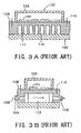
- FIGS. 3A and Figure 3B are diagrams illustrating the arrangement of a conventional device different from that of Figure 1A and Figure 1B , Figure 3A being a cross-sectional view in the front elevation direction and Figure 3B being a cross-sectional view in the side direction.
- heat-generating elements 101 are incorporated as structural elements of module elements 107, and are arranged on a plate member 108.
- the periphery of a heat-generating element 101 is covered by a cover member 109 and the peripheral region of plate member 108 is mounted on heat sink 102 by means of mounting screws 110.
- the heat sink 102 performs cooling of heat-generating elements 101 by means of coolant 106, being formed with heat radiating fins 111 and a channel 112 constituting a passage for coolant 106.
- cooling of the heat-generating elements 101 is performed uniformly by the heat exchange action of cooling medium 106 flowing through the interior of heat sink 102, not withstanding this uniformity a certain degree of temperature difference is produced between portions where passage for coolant 106 is provided and portions other than these, so complete uniformity is not achieved.
- the coolant 106 advances through coolant passages 103 or channels 112, so a certain time is unavoidably required for it to reach coolant outlet 105 from coolant inlet 104. Transiently, therefore, a large temperature difference can be produced between portions that have been reached by coolant 106 and portions that have not yet been reached thereby.
- the distance of the two points P1 and P2 shown in Figure 1A is short since these are positions on mutually adjacent heat-generating elements 101.
- coolant passage 103 is of a meandering shape, even though the portion of point P1 is cooled by coolant 106, the portion of point P2 is still not yet cooled, so a condition in which there is a large temperature difference between the two points is produced. A large tensile heat stress is thereby generated between these, with the result that this heat stress is applied to the heat-generating element 101 also.
- FR-A-2 715 773 is concerned with a cooling device for an electronic component and EP-A-0 341 950 is concerned with a cooling structure of an integrated circuit.
- one object of the present invention is to provide a novel cooling device for heat-generating elements wherein cooling by the coolant is performed uniformly even under transient conditions and it is thereby possible to prevent application of large thermal stress to the heat-generating elements.
- the present invention is constructed as follows. Specifically, a cooling device according to claim 1 is provided.
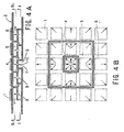
- Figure 4A and Figure 4B are views given in explanation of the construction of a first embodiment of the present invention, Figure 4A being a vertical cross-sectional view and Figure 4B being a view in the direction of the arrows B1-B1 of Figure 4A .
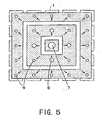
- Figure 5 is a view in the direction of the arrows II-II of Figure 4A .
- a plurality of heat-generating elements 1 are arranged in checkerboard fashion on the surface on one side of a heat sink 2.
- a coolant introduction chamber 3 is formed below a central heat-generating element 1 (hereinbelow, for convenience in description, directions are indicated by “upwards” or “downwards”, but the actual heat sink 2 could be mounted in many different orientations, so these terms refer only to its shape in the drawings rather than its actual physical orientation).
- a first coolant contact chamber 4 is formed so as to surround this coolant introduction chamber 3; a second coolant contact chamber 5 is formed so as to surround this first coolant contact chamber 4 and a third coolant contact chamber 6 is formed so as to surround this second coolant contact chamber 5.
- a single central nozzle 7 is formed between the coolant introduction chamber 3 and coolant contact chamber 4 so as to be positioned in a central position of these chambers. Also, a plurality of peripheral nozzles 8 of diameter smaller than central nozzle 7 are formed between first coolant contact chamber 4 and second coolant contact chamber 5. In addition, a plurality of peripheral nozzles 9 of diameter even smaller than the diameter of peripheral nozzles 8 are formed between the second coolant contact chamber 5 and third coolant contact chamber 6.
- Figure 5 is a view given in explanation of the magnitudes of the respective diameters of the above nozzles 7 to 9 and their mutual positional relationships.
- the central nozzle 7 that is formed between coolant introduction chamber 3 and first coolant contact chamber 4 is of the largest diameter; the peripheral nozzles 8 that are formed between first coolant contact chamber 4 and second coolant contact chamber 5 have the next largest diameter, while the peripheral nozzles 9 that are formed between second coolant contact chamber 5 and third coolant contact chamber 6 have the smallest diameter.
- the plurality of peripheral nozzles 8, 9 are formed so as to be positioned in radial fashion about central nozzle 7 as center.
- peripheral nozzles 8 of second largest diameter and peripheral nozzles 9 of smallest diameter are present between first coolant contact chamber 4 and second coolant contact chamber 5, the positions of peripheral nozzles 9 are further from central nozzle 7 than the positions of peripheral nozzles 8. A relationship is thereby established such that the diameter of the peripheral nozzles becomes progressively smaller as distance from the central nozzle 7 is increased.
- coolant 10 is fed from a coolant inlet, not shown, this coolant 10 is introduced into coolant introduction chamber 3 so that the interior of coolant introduction chamber 3 becomes filled with coolant 10. Coolant 10 is injected from central nozzle 7 towards the back face side of the heat sink 2 where the heat-generating elements 1 are arranged.
- Coolant 10 injected from central nozzle 7 straight away fills the interior of first coolant contact chamber 4 and is injected towards the back face side of second coolant contact chamber 5 from peripheral nozzles 8 (and peripheral nozzles 9). Furthermore, the coolant 10 injected from peripheral nozzles 8 straight away fills second coolant contact chamber 5 and is injected towards the back face side within third coolant contact chamber 6 from peripheral nozzles 9. After this, coolant 10 that has filled the third coolant contact chamber 6 is delivered to a coolant outlet, not shown, whence it is discharged to outside heat sink 2.
- FIG. 4A, Figure 4B and Figure 5 indicate the direction of flow of coolant 10. That is, cooling of heat-generating elements 1 is effected by performing heat exchange wherein coolant 10 is introduced 5 into coolant introduction chamber 3 from the coolant inlet and then is sequentially fed to first coolant contact chamber 4, second coolant contact chamber 5 and third coolant contact chamber 6, being thereby brought into contact with the back face side of heat sink 2 where the heat-generating elements 1 are arranged.
- the cooling range spreads in radial fashion from the central nozzle 7 as center, the cooling region is practically uniformly distributed in the circumferential direction, so, even in the transitional period, there is no possibility of large tensile heat stress being generated on the heat-generating elements 1 relative to the peripheral heat-generating elements and there is no possibility of heat-generating elements 1 being damaged by heat stress.
- the aperture (hole diameter) of central nozzle 7 and peripheral nozzles 8 and 9 is made progressively larger approaching the middle and progressively smaller approaching the periphery.
- the hole diameter is made progressively larger for nozzles nearer to the center so their flow rates are higher, making it possible to equalize the average outflow speed of the jets from the nozzles. If we now assume that the mean outflow speed of the jet is u and the heat transfer factor at the impact point with which this jet collides is ⁇ , the relationship between ⁇ and u can be expressed by the following expression (1) (see: Mechanical Association of Japan, Heat Transfer Engineering Data, 4th edition p66 (66)).
- ⁇ is the fluid thermal conductivity
- D is the hole diameter
- Pr is the Prandtl number
- Red is the Reynold's number
- the Reynold's number Red can be expressed by expression (2), where the coefficient of fluid dynamic viscosity is v.
- the mean outflow velocity u in expression (2) can be expressed by expression (3).
- one end of a passage 11 is connected to a coolant inlet, not shown, while the other end of this passage 11 is connected to a coolant introduction chamber 3.
- First coolant contact chambers 4a, 4b are formed so as to surround this coolant introduction chamber 3;
- second coolant contact chambers 5a, 5b are formed so as to surround these first coolant contact chambers 4a, 4b and
- third coolant contact chambers 6a, 6b are formed so as to surround these second coolant contact chambers 5a, 5b.
- Central nozzles 7a, 7b are formed between the coolant introduction chamber 3 and first coolant contact chambers 4a, 4b so as to be positioned in central positions of these chambers. Also, peripheral nozzles 8a, 8b of diameter smaller than central nozzles 7a, 7b are formed between first coolant contact chambers 4a, 4b and second coolant contact chambers 5a, 5b. In addition, peripheral nozzles 9a, 9b of diameter even smaller than the diameter of peripheral nozzles 8a, 8b are formed between the second coolant contact chambers 5a, 5b and third coolant contact chambers 6a, 6b.
- the action of the second embodiment is the same as that of the first embodiment, so description thereof will not be repeated.
- uniform cooling of the heat-generating elements 1 can be performed and large tensile heat stress can be prevented from being generated at heat-generating elements 1.
- passage 11 is only in contact with one side of coolant introduction chamber 3, a flow of speed distribution of practically parabolic shape is produced that is stable towards the central nozzles 7A, 7B in this passage 11.
- FIG. 7A and Figure 7B are views given in explanation of the construction of a third embodiment of the present invention, Figure 7A being a vertical cross-sectional view and Figure 7B being a view in the direction of the arrows B3-B3 of Figure 7A .
- this third embodiment just as in the case of the second embodiment, a construction is illustrated in which heat-generating elements 1 are arranged on two outer surfaces on both sides of heat sink 2; however, unlike the second embodiment, two passages 11a, 11b are connected to both sides of coolant introduction chamber 3. The flow rate of coolant 10 from the coolant inlet to coolant introduction chamber 3 can thereby be made larger than in the case of the second embodiment.
- Figure 8 is a transverse cross-sectional view corresponding to Figure 7B given in explanation of the construction of major parts of a fourth embodiment of the present invention.
- Figure 7B since the introduction ports of the two passages 11a, 11b are positioned facing each other, coolant 10 flowing through these passages collides in the coolant introduction chamber 3, reducing the flow speed within coolant introduction chamber 3.
- the introduction ports of the two passages 11a, 11b are in mutually offset positions, so coolant 10 flowing through each passage has a vortical speed component in the coolant introduction chamber 3, so no large reduction in the flow speed takes place.
- the heat transfer factor at the location where the jet collides with the back face side of the heat-generating elements 1 can therefore be increased.
- Figure 9 is a vertical cross-sectional view corresponding to Figure 7A illustrating the construction of major parts of a fifth embodiment of the present invention.
- a partition 12 for partitioning coolant 10 flowing from passage 11a and coolant 10 flowing from passage 11b into coolant introduction chamber 3 is formed in an inclined fashion with respect to the respective inflow directions.
- the coolant 10 from the respective passages is therefore injected from central nozzles 7A, 7B in a condition wherein little loss of pressure is created, since mutual collision within coolant introduction chamber 3 cannot occur.
- FIG 10A and Figure 10B are views given in explanation of the construction of an illustrative embodiment, Figure 10A being a plan view and Figure 10B a vertical crosa-sectional view.
- a module type element 13 is incorporated in heat sink 14 and heat-generating elements 1 are incorporated as constituent elements of module type element 13.
- a plurality of heat-generating elements 1 are arranged on the surface of a plate member 15 so as to constitute overall a practically rectangular shape, the periphery of these heat-generating elements 1 being covered by a cover member 16.
- Plate member 15 is mounted on heat sink 14 by mounting screws 17 in the vicinity of the peripheral region thereof.
- a coolant introduction chamber 18 and coolant contact chamber 19 are formed in the interior of heat sink 14, a plurality of nozzles 20 being formed between these chambers.
- Coolant contact chamber 19 has a practically rectangular-shaped face including the back face side of all of the heat-generating elements 1; this coolant contact chamber 19 and coolant introduction chamber 18 have faces of practically the same shape.
- the plurality of nozzles 20 have mutually identical diameters.
- the overall shape of heat-generating elements 1 is practically rectangular and they have a comparatively small area, so a single coolant contact chamber 19 is sufficient, cooling of all of the heat-generating elements 1 being performed by coolant 10 within this coolant contact chamber 19.
- coolant 10 flowing in from coolant inlet 21 immediately fully fills coolant introduction chamber 18 and jets are injected from nozzles 20. Injection from nozzles 20 is then performed practically simultaneously, so there is no possibility of tensile heat stress being generated between heat-generating elements 1.
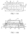
- Figure 11A and Figure 11B are views given in explanation of the construction of an illustrative embodiment, Figure 11A being a plan view and Figure 11B a vertical cross-sectional view.
- Figure 11A and Figure 11B differ from Figure 10A and Figure 10B is that an annular groove 23 is formed in the opposite face of heat sink 14 facing plate member 15, and an O-ring 24 is embedded in this annular groove 23.
- This O-ring 24 is pressed into contact with heat sink 14 by plate member 15 by the tightening force when plate member 15 is tightened on to heat sink 14 by mounting screws 17.
- annular groove 23 is formed in the vicinity of the wall of heat sink 14 that forms the coolant contact chamber 19 and an O-ring 24 is arranged within this annular groove 23, high cooling performance can be maintained without leakage of coolant 10 from coolant contact chamber 19.
- FIG 12A and Figure 12B are views given in explanation of the construction of an illustrative embodiment, Figure 12A being a plan view and Figure 12B a vertical cross-sectional view.
- Module type element 25 in this embodiment is provided with a cover member 26 comprising a cylindrical body 27 and cover 28.
- a hole 29 is formed in the middle of plate member 15 and a mounting boss 30 formed in the middle of heat sink 14 passes through this hole 29.
- cover 28 is tightened onto mounting boss 30 by tightening screw 31
- the end face of cylindrical body 27 is subjected to pressing force onto plate member 15 by this tightening force.
- O-ring 24 therefore assumes a condition in which it is compressed against the back face side of plate member 15.
- Figure 13A and Figure 13B are views given in explanation of the construction of an illustrative embodiment, Figure 13A being a plan view and Figure 13B a vertical cross-sectional view.
- the construction of Figure 13A and Figure 13B is the same as the construction of Figure 10A and Figure 10B , but the direction of mounting of coolant inlet 21 and coolant outlet 22 are different.
- the planar shape of the region of arrangement of the entirety of heat-generating elements 1 is practically rectangular and the planar shape of coolant contact chamber 19 and coolant introduction chamber 18 corresponding thereto is also practically rectangular. If the direction perpendicular to the long side of this rectangle is taken as the Y1 direction and the direction parallel thereto as the Y2 direction, the direction of mounting coolant inlet 21 and coolant outlet 22 in this embodiment is the Y1 direction whereas the direction of mounting of coolant inlet 21 and coolant outlet 22 in the sixth embodiment shown in Figure 13A is the Y2 direction.
- the thermal resistance from the coolant to the heat-generating elements 1 is reduced, making it possible to increase the heat transfer factor.
- the reason for this is that the ratio of interference of the coolant after injection from the upstream nozzles with the jets injected from the downstream nozzles is much smaller in the case of the Y1 direction than in the case of the Y2 direction.
- Figure 14 is a thermal resistance/flow rate characteristic for the case where the direction of mounting coolant inlet 21 and coolant outlet 22 is a direction perpendicular to the long side and for the case where this direction is a direction parallel thereto. As can be seen from this Figure, the thermal resistance is appreciably less in the case where the mounting direction is the perpendicular direction.
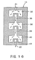
- Figure 15A and Figure 15B are views given in explanation of the construction of an illustrative embodiment, Figure 15A being a lateral cross-sectional view and Figure 15B being a view in the direction of the arrows B4-B4 of Figure 15A . Also, Figure 16 is a view in the direction of the arrows XIII-XIII of Figure 15A . As shown in Figure 15A , in this embodiment, the region of arrangement of heat-generating elements 1 is divided into first to third arrangement regions R1 to R3.
- This embodiment is therefore suitable when a large number of heat-generating elements 1 are to be cooled.
- coolant from coolant inlet 21 is introduced into coolant introduction chamber 32 and coolant within coolant introduction chamber 32 is fed into first coolant contact chamber 34 by being injected from nozzles 33; cooling of heat-generating elements 1 is effected by collision of the coolant with the back face side of plate member 15.
- coolant introduction chamber 32 constitutes a wide space having an approximately inverted channel-shaped cross section.
- first intermediate introduction chamber 36 The coolant within first coolant contact chamber 34 is fed into first intermediate introduction chamber 36 through a narrow passage 35. As shown in Figure 16 , this first intermediate introduction chamber 36 also has a space having the same shape as coolant introduction chamber 32. The coolant within this intermediate introduction chamber 36 is fed into second coolant contact chamber 38 by being injected from nozzles 37 and cooling of heat-generating elements 1 is effected by collision of the coolant with the back face side of plate member 15.
- the coolant within second coolant contact chamber 38 is fed into a second intermediate introduction chamber 40 through passage 39 and the coolant within second intermediate chamber 40 is fed into a third coolant contact chamber 42 by being injected from nozzles 41; cooling of heat-generating elements 1 is effected by collision of the coolant with the back face side of plate member 15.
- third coolant contact chamber 42 then passes through a narrow passage 43 and flows to outside heat sink 14 through coolant outlet 22.
- first to third coolant contact chambers 34, 38, 42 are provided respectively corresponding to first to third arrangement regions R1 to R3 and, in addition, a first intermediate introduction chamber 36 is provided between first coolant contact chamber 34 and second coolant contact chamber 38 while a second coolant introduction chamber 40 is provided between second coolant contact chamber 38 and third coolant contact chamber 42. Consequently, mutual interference of jets of coolant injected from nozzles 33, 37 and 41 is prevented, making it possible to achieve a smooth flow of coolant and thereby making it possible to improve the efficiency of cooling.
- a construction is adopted wherein two types of chambers are provided in the heat sink, namely, coolant introduction chambers and coolant contact chambers and nozzles that inject coolant towards the back face side of the heat-generating elements are provided between these chambers, so, even transiently, uniform cooling by the coolant can be achieved, making it possible to prevent application of large thermal stress to the heat-generating elements.
Landscapes
- Engineering & Computer Science (AREA)
- Physics & Mathematics (AREA)
- Thermal Sciences (AREA)
- Mechanical Engineering (AREA)
- General Engineering & Computer Science (AREA)
- Cooling Or The Like Of Semiconductors Or Solid State Devices (AREA)
- Cooling Or The Like Of Electrical Apparatus (AREA)
- Details Of Measuring And Other Instruments (AREA)
Description
- This application claims benefit of priority to
Japanese Application number JP 2001-237789 filed August 6, 2001 - The present invention relates to a cooling device for heat-generating elements that performs cooling of heat-generating elements by heat exchange action with a coolant.
- Semiconductor elements such as IGBTs are employed in equipment of various types including in particular power converters such as inverters. These semiconductor elements generate heat during operation of the equipment and so constitute heat-generating elements whose temperature rises to a considerable degree. A prescribed value (rating) is laid down in respect of the heat endurance temperature of these semiconductor elements, so rise of temperature above a fixed value must be prevented by cooling the semiconductor elements during operation of the equipment. Whether or not efficient cooling of the semiconductor elements can be achieved is therefore extremely important in regard to the performance of the equipment.
-
Figure 1A and Figure 1B are diagrams illustrating the layout of a conventional cooling device for a heat-generating element,Figure 1A being a plan view andFigure 1B being a cross-sectional view. In these Figures, heat-generatingelements 101 are arranged in checkerboard (sometimes called "go" in Japanese) fashion on the surface of aheat sink 102.Heat sink 102 is formed of material of good thermal conductivity such as copper or aluminum and is formed withcoolant passages 103 that have bending points at a plurality of locations in its interior. - Thus, when coolant 106 (for example a liquid such as water) is delivered from a
coolant inlet 104, thiscoolant 106 advances in meandering fashion through the interior ofcoolant passage 103 so that cooling of the heat-generatingelements 101 is performed in uniform fashion by the heat exchanging action ofcoolant 106 during this advance. After this heat exchanging has been completed, thecoolant 106 is then discharged fromcoolant outlet 105 tooutside heat sink 102. - It should be noted that, although in this prior art, the case was illustrated in which heat-generating
element 101 were arranged in checkerboard fashion, heat-generatingelements 101 could be arranged in a zigzag fashion.Figure 2A and Figure 2B are diagrams illustrating the differences between the checkerboard arrangement and the zigzag arrangement. In the checkerboard arrangement, as shown inFigure 2A , the positions of heat-generatingelements 101 are in an aligned arrangement in each column and each row; in the zigzag arrangement shown inFigure 2B , the positions of heat-generatingelements 101 in a given row and the positions of heat-generatingelements 101 in the adjacent row are offset. -
Figure 3A and Figure 3B are diagrams illustrating the arrangement of a conventional device different from that ofFigure 1A and Figure 1B ,Figure 3A being a cross-sectional view in the front elevation direction andFigure 3B being a cross-sectional view in the side direction. In these Figures, heat-generatingelements 101 are incorporated as structural elements ofmodule elements 107, and are arranged on aplate member 108. The periphery of a heat-generatingelement 101 is covered by acover member 109 and the peripheral region ofplate member 108 is mounted onheat sink 102 by means of mountingscrews 110. In the same way as in the case of the prior art ofFigure 1A and Figure 1B , theheat sink 102 performs cooling of heat-generatingelements 101 by means ofcoolant 106, being formed withheat radiating fins 111 and achannel 112 constituting a passage forcoolant 106. - Thus, in the cooling device shown in
Figure 3A and Figure 3B , when thecoolant 106 is fed in fromcoolant inlet 104, thiscoolant 106 advances throughchannel 112 betweenheat radiating fins 111 and cooling of the heat-generatingelements 101 is uniformly effected by the heat exchange action ofcoolant 106 during this advance. - Although, as mentioned above, cooling of the heat-generating
elements 101 is performed uniformly by the heat exchange action ofcooling medium 106 flowing through the interior ofheat sink 102, not withstanding this uniformity a certain degree of temperature difference is produced between portions where passage forcoolant 106 is provided and portions other than these, so complete uniformity is not achieved. - Furthermore, with a conventional cooling device, the
coolant 106 advances throughcoolant passages 103 orchannels 112, so a certain time is unavoidably required for it to reachcoolant outlet 105 fromcoolant inlet 104. Transiently, therefore, a large temperature difference can be produced between portions that have been reached bycoolant 106 and portions that have not yet been reached thereby. For example, the distance of the two points P1 and P2 shown inFigure 1A is short since these are positions on mutually adjacent heat-generatingelements 101. However, sincecoolant passage 103 is of a meandering shape, even though the portion of point P1 is cooled bycoolant 106, the portion of point P2 is still not yet cooled, so a condition in which there is a large temperature difference between the two points is produced. A large tensile heat stress is thereby generated between these, with the result that this heat stress is applied to the heat-generatingelement 101 also. -
FR-A-2 715 773 EP-A-0 341 950 is concerned with a cooling structure of an integrated circuit. - Accordingly, one object of the present invention is to provide a novel cooling device for heat-generating elements wherein cooling by the coolant is performed uniformly even under transient conditions and it is thereby possible to prevent application of large thermal stress to the heat-generating elements.
- In order to achieve the above object, the present invention is constructed as follows. Specifically, a cooling device according to
claim 1 is provided. - A more complete appreciation of the present invention and many of the attendant advantages thereof will be readily obtained as the same becomes better understood by reference to the following detailed description when considered in connection with the accompanying drawings,
wherein: -
Figure 1A and Figure 1B are diagrams illustrating the construction of a conventional cooling device for heat-generating elements, especiallyFigure 1A being a plan view andFigure 1B a cross-sectional view; -
Figure 2A and Figure 2B are views given in explanation of the differences between a checkerboard arrangement and a zigzag arrangement; -
Figure 3A and Figure 3B are diagrams illustrating the construction of a further prior art device,Figure 3A being a cross-sectional view in the front elevation direction andFigure 3B being a cross-sectional view in the lateral direction; -
Figure 4A and Figure 4B are views given in explanation of the construction of a first embodiment of the present invention,Figure 4A being an axial (longitudinal or vertical) cross-sectional view andFigure 4B being a view in the direction of the arrows B1-B1 ofFigure 4A ; -
Figure 5 is a view in the direction of the arrows II-II ofFigure 4A ; -
Figure 6A and Figure 6B are views given in explanation of the construction of a second embodiment of the present invention,Figure 6A being a vertical cross-sectional view andFigure 6B being a view in the direction of arrows B2-B2 ofFigure 6A ; -
Figure 7A and Figure 7B are views given in explanation of the construction of a third embodiment of the present invention,Figure 7A being a vertical cross-sectional view andFigure 7B being a view in the direction of the arrows B3-B3 ofFigure 7A ; -
Figure 8 is a transverse cross-sectional view given in explanation of the construction of major parts of a fourth embodiment of present invention; -
Figure 9 is a vertical cross-sectional view illustrating the construction of major parts of a fifth embodiment of the present invention; -
Figure 10A and Figure 10B are views given in explanation of the construction of an illustrative embodiment,Figure 10A being a plan view andFigure 10B a vertical cross-sectional view; -
Figure 11A and Figure 11B are views given in explanation of the construction of an illustrative embodiment,Figure 11A being a plan view andFigure 11B a vertical cross-sectional view; -
Figure 12A and Figure 12B are views given in explanation of the construction of an illustrative embodiment,Figure 12A being a plan view andFigure 12B a vertical cross-sectional view; -
Figure 13A and Figure 13B are views given in explanation of the construction of a further illustrative embodiment,Figure 13A being a plan view andFigure 13B a vertical cross-sectional view; -
Figure 14 is a thermal resistance-flow rate characteristic for the case where the direction of mountingcoolant inlet 21 andcoolant outlet 22 is a direction perpendicular to the long side of a practically (substantially) rectangular region of arrangement and for the case where this direction is a direction parallel thereto; -
Figure 15A and Figure 15B are views given in explanation of the construction of a further illustrative embodiment,Figure 15A being a lateral cross-sectional view andFigure 15B being a view in the direction of the arrows B4-B4 ofFigure 15A ; and -
Figure 16 is a view in the direction of the arrows XIII-XIII ofFigure 15A . - Referring now to the drawings, wherein like reference numerals designate identical or corresponding parts throughout the several views, and more particularly to
Figure 4-16 thereof, one embodiment of the present invention will be described. -
Figure 4A and Figure 4B are views given in explanation of the construction of a first embodiment of the present invention,Figure 4A being a vertical cross-sectional view andFigure 4B being a view in the direction of the arrows B1-B1 ofFigure 4A .Figure 5 is a view in the direction of the arrows II-II ofFigure 4A . - In these Figures, a plurality of heat-generating
elements 1 are arranged in checkerboard fashion on the surface on one side of aheat sink 2. As shown inFigure 4A , acoolant introduction chamber 3 is formed below a central heat-generating element 1 (hereinbelow, for convenience in description, directions are indicated by "upwards" or "downwards", but theactual heat sink 2 could be mounted in many different orientations, so these terms refer only to its shape in the drawings rather than its actual physical orientation). A firstcoolant contact chamber 4 is formed so as to surround thiscoolant introduction chamber 3; a second coolant contact chamber 5 is formed so as to surround this firstcoolant contact chamber 4 and a thirdcoolant contact chamber 6 is formed so as to surround this second coolant contact chamber 5. - A single central nozzle 7 is formed between the
coolant introduction chamber 3 andcoolant contact chamber 4 so as to be positioned in a central position of these chambers. Also, a plurality ofperipheral nozzles 8 of diameter smaller than central nozzle 7 are formed between firstcoolant contact chamber 4 and second coolant contact chamber 5. In addition, a plurality ofperipheral nozzles 9 of diameter even smaller than the diameter ofperipheral nozzles 8 are formed between the second coolant contact chamber 5 and thirdcoolant contact chamber 6. -
Figure 5 is a view given in explanation of the magnitudes of the respective diameters of the above nozzles 7 to 9 and their mutual positional relationships. As shown in this Figure, the central nozzle 7 that is formed betweencoolant introduction chamber 3 and firstcoolant contact chamber 4 is of the largest diameter; theperipheral nozzles 8 that are formed between firstcoolant contact chamber 4 and second coolant contact chamber 5 have the next largest diameter, while theperipheral nozzles 9 that are formed between second coolant contact chamber 5 and thirdcoolant contact chamber 6 have the smallest diameter. The plurality ofperipheral nozzles peripheral nozzles 8 of second largest diameter andperipheral nozzles 9 of smallest diameter are present between firstcoolant contact chamber 4 and second coolant contact chamber 5, the positions ofperipheral nozzles 9 are further from central nozzle 7 than the positions ofperipheral nozzles 8. A relationship is thereby established such that the diameter of the peripheral nozzles becomes progressively smaller as distance from the central nozzle 7 is increased. - Next, the action of the first embodiment constructed as above will be described. When
coolant 10 is fed from a coolant inlet, not shown, thiscoolant 10 is introduced intocoolant introduction chamber 3 so that the interior ofcoolant introduction chamber 3 becomes filled withcoolant 10.Coolant 10 is injected from central nozzle 7 towards the back face side of theheat sink 2 where the heat-generatingelements 1 are arranged. -
Coolant 10 injected from central nozzle 7 straight away fills the interior of firstcoolant contact chamber 4 and is injected towards the back face side of second coolant contact chamber 5 from peripheral nozzles 8 (and peripheral nozzles 9). Furthermore, thecoolant 10 injected fromperipheral nozzles 8 straight away fills second coolant contact chamber 5 and is injected towards the back face side within thirdcoolant contact chamber 6 fromperipheral nozzles 9. After this,coolant 10 that has filled the thirdcoolant contact chamber 6 is delivered to a coolant outlet, not shown, whence it is discharged tooutside heat sink 2. - The arrows in
Figure 4A, Figure 4B andFigure 5 indicate the direction of flow ofcoolant 10. That is, cooling of heat-generatingelements 1 is effected by performing heat exchange whereincoolant 10 is introduced 5 intocoolant introduction chamber 3 from the coolant inlet and then is sequentially fed to firstcoolant contact chamber 4, second coolant contact chamber 5 and thirdcoolant contact chamber 6, being thereby brought into contact with the back face side ofheat sink 2 where the heat-generatingelements 1 are arranged. - In this case, in
Figure 4A , tensile stress due to thermal stress does act on the heat-generatingelement 1 positioned directly abovecoolant introduction chamber 3 and central nozzle 7 but, sinceperipheral nozzles elements 1 is likewise performed in a manner spreading in radial fashion. Consequently, since the peripheral heat-generatingelements 1 are not deformed since they are not yet cooled, the tensile stress is uniformly distributed in the circumferential direction. Also, since the cooling range spreads in radial fashion from the central nozzle 7 as center, the cooling region is practically uniformly distributed in the circumferential direction, so, even in the transitional period, there is no possibility of large tensile heat stress being generated on the heat-generatingelements 1 relative to the peripheral heat-generating elements and there is no possibility of heat-generatingelements 1 being damaged by heat stress. - The reason why the aperture (hole diameter) of central nozzle 7 and
peripheral nozzles 


- As a result, from the above expression (1) to the expression (3), it can be seen that the heat transfer factor α is proportional to D/Q raised to the power 0.5. Consequently, the heat transfer factor at the back face side, with which the jet collides, of each heat-generating
element 1 can be made practically the same by making the whole diameter of the central nozzle 7 where the flow rate is concentrated large and by making the hole diameter of the peripheral nozzles where the flow rate is distributed small. For such reasons, the hole diameter of the nozzles is made progressively larger towards the middle and progressively smaller towards the periphery. - It should be noted that although, in the first embodiment, the case where the number of coolant contact chambers is three was described, this number of coolant contact chambers could be any number of two or more.
- The construction of a second embodiment of the present invention is described with reference to
Figure 6A and Figure 6B, Figure 6A being a vertical cross-sectional view andFigure 6B being a view along the arrows B2-B2 ofFigure 6A . This embodiment shows the case where heat-generatingelements 1 are arranged on two faces on both sides ofheat sink 2. - Specifically, in
Figure 6A , one end of apassage 11 is connected to a coolant inlet, not shown, while the other end of thispassage 11 is connected to acoolant introduction chamber 3. Firstcoolant contact chambers coolant introduction chamber 3; secondcoolant contact chambers coolant contact chambers coolant contact chambers coolant contact chambers -
Central nozzles coolant introduction chamber 3 and firstcoolant contact chambers peripheral nozzles central nozzles coolant contact chambers coolant contact chambers peripheral nozzles peripheral nozzles coolant contact chambers coolant contact chambers - The action of the second embodiment is the same as that of the first embodiment, so description thereof will not be repeated. In the second embodiment, just as in the case of the first embodiment, uniform cooling of the heat-generating
elements 1 can be performed and large tensile heat stress can be prevented from being generated at heat-generatingelements 1. Also, in this second embodiment, sincepassage 11 is only in contact with one side ofcoolant introduction chamber 3, a flow of speed distribution of practically parabolic shape is produced that is stable towards the central nozzles 7A, 7B in thispassage 11. -
Figure 7A and Figure 7B are views given in explanation of the construction of a third embodiment of the present invention,Figure 7A being a vertical cross-sectional view andFigure 7B being a view in the direction of the arrows B3-B3 ofFigure 7A . In this third embodiment, just as in the case of the second embodiment, a construction is illustrated in which heat-generatingelements 1 are arranged on two outer surfaces on both sides ofheat sink 2; however, unlike the second embodiment, twopassages coolant introduction chamber 3. The flow rate ofcoolant 10 from the coolant inlet tocoolant introduction chamber 3 can thereby be made larger than in the case of the second embodiment. -
Figure 8 is a transverse cross-sectional view corresponding toFigure 7B given in explanation of the construction of major parts of a fourth embodiment of the present invention. In the case ofFigure 7B , since the introduction ports of the twopassages coolant 10 flowing through these passages collides in thecoolant introduction chamber 3, reducing the flow speed withincoolant introduction chamber 3. However, in the case ofFigure 8 , the introduction ports of the twopassages coolant 10 flowing through each passage has a vortical speed component in thecoolant introduction chamber 3, so no large reduction in the flow speed takes place. The heat transfer factor at the location where the jet collides with the back face side of the heat-generatingelements 1 can therefore be increased. -
Figure 9 is a vertical cross-sectional view corresponding toFigure 7A illustrating the construction of major parts of a fifth embodiment of the present invention. Specifically, in this embodiment, apartition 12 for partitioningcoolant 10 flowing frompassage 11a andcoolant 10 flowing frompassage 11b intocoolant introduction chamber 3 is formed in an inclined fashion with respect to the respective inflow directions. Thecoolant 10 from the respective passages is therefore injected from central nozzles 7A, 7B in a condition wherein little loss of pressure is created, since mutual collision withincoolant introduction chamber 3 cannot occur. -
Figure 10A and Figure 10B are views given in explanation of the construction of an illustrative embodiment,Figure 10A being a plan view andFigure 10B a vertical crosa-sectional view. In this embodiment, amodule type element 13 is incorporated inheat sink 14 and heat-generatingelements 1 are incorporated as constituent elements ofmodule type element 13. A plurality of heat-generatingelements 1 are arranged on the surface of aplate member 15 so as to constitute overall a practically rectangular shape, the periphery of these heat-generatingelements 1 being covered by acover member 16.Plate member 15 is mounted onheat sink 14 by mountingscrews 17 in the vicinity of the peripheral region thereof. - A
coolant introduction chamber 18 andcoolant contact chamber 19 are formed in the interior ofheat sink 14, a plurality ofnozzles 20 being formed between these chambers.Coolant contact chamber 19 has a practically rectangular-shaped face including the back face side of all of the heat-generatingelements 1; thiscoolant contact chamber 19 andcoolant introduction chamber 18 have faces of practically the same shape. Also, the plurality ofnozzles 20 have mutually identical diameters. - In this sixth embodiment, the overall shape of heat-generating
elements 1 is practically rectangular and they have a comparatively small area, so a singlecoolant contact chamber 19 is sufficient, cooling of all of the heat-generatingelements 1 being performed bycoolant 10 within thiscoolant contact chamber 19. In this case,coolant 10 flowing in fromcoolant inlet 21 immediately fully fillscoolant introduction chamber 18 and jets are injected fromnozzles 20. Injection fromnozzles 20 is then performed practically simultaneously, so there is no possibility of tensile heat stress being generated between heat-generatingelements 1. -
Figure 11A and Figure 11B are views given in explanation of the construction of an illustrative embodiment,Figure 11A being a plan view andFigure 11B a vertical cross-sectional view. The respect in whichFigure 11A and Figure 11B differ fromFigure 10A and Figure 10B is that anannular groove 23 is formed in the opposite face ofheat sink 14 facingplate member 15, and an O-ring 24 is embedded in thisannular groove 23. This O-ring 24 is pressed into contact withheat sink 14 byplate member 15 by the tightening force whenplate member 15 is tightened on toheat sink 14 by mountingscrews 17. - In this way, with this embodiment, since an
annular groove 23 is formed in the vicinity of the wall ofheat sink 14 that forms thecoolant contact chamber 19 and an O-ring 24 is arranged within thisannular groove 23, high cooling performance can be maintained without leakage ofcoolant 10 fromcoolant contact chamber 19. -
Figure 12A and Figure 12B are views given in explanation of the construction of an illustrative embodiment,Figure 12A being a plan view andFigure 12B a vertical cross-sectional view.Module type element 25 in this embodiment is provided with acover member 26 comprising acylindrical body 27 andcover 28. Ahole 29 is formed in the middle ofplate member 15 and a mountingboss 30 formed in the middle ofheat sink 14 passes through thishole 29. Thus, whencover 28 is tightened onto mountingboss 30 by tighteningscrew 31, the end face ofcylindrical body 27 is subjected to pressing force ontoplate member 15 by this tightening force. O-ring 24 therefore assumes a condition in which it is compressed against the back face side ofplate member 15. - With this eighth embodiment, since sufficient pressing force can be supplied to O-
ring 24 by asingle tightening screw 31, the task of assembly can be conducted in a straightforward fashion, improving efficiency of the assembly task. -
Figure 13A and Figure 13B are views given in explanation of the construction of an illustrative embodiment,Figure 13A being a plan view andFigure 13B a vertical cross-sectional view. The construction ofFigure 13A and Figure 13B is the same as the construction ofFigure 10A and Figure 10B , but the direction of mounting ofcoolant inlet 21 andcoolant outlet 22 are different. - Specifically, as shown in
Figure 13A , the planar shape of the region of arrangement of the entirety of heat-generatingelements 1 is practically rectangular and the planar shape ofcoolant contact chamber 19 andcoolant introduction chamber 18 corresponding thereto is also practically rectangular. If the direction perpendicular to the long side of this rectangle is taken as the Y1 direction and the direction parallel thereto as the Y2 direction, the direction of mountingcoolant inlet 21 andcoolant outlet 22 in this embodiment is the Y1 direction whereas the direction of mounting ofcoolant inlet 21 andcoolant outlet 22 in the sixth embodiment shown inFigure 13A is the Y2 direction. - Thus, by making the mounting direction of
coolant inlet 21 andcoolant outlet 22 the Y1 direction which is perpendicular to the long side, the thermal resistance from the coolant to the heat-generatingelements 1 is reduced, making it possible to increase the heat transfer factor. The reason for this is that the ratio of interference of the coolant after injection from the upstream nozzles with the jets injected from the downstream nozzles is much smaller in the case of the Y1 direction than in the case of the Y2 direction. -
Figure 14 is a thermal resistance/flow rate characteristic for the case where the direction of mountingcoolant inlet 21 andcoolant outlet 22 is a direction perpendicular to the long side and for the case where this direction is a direction parallel thereto. As can be seen from this Figure, the thermal resistance is appreciably less in the case where the mounting direction is the perpendicular direction. -
Figure 15A and Figure 15B are views given in explanation of the construction of an illustrative embodiment,Figure 15A being a lateral cross-sectional view andFigure 15B being a view in the direction of the arrows B4-B4 ofFigure 15A . Also,Figure 16 is a view in the direction of the arrows XIII-XIII ofFigure 15A . As shown inFigure 15A , in this embodiment, the region of arrangement of heat-generatingelements 1 is divided into first to third arrangement regions R1 to R3. - This embodiment is therefore suitable when a large number of heat-generating
elements 1 are to be cooled. - coolant from
coolant inlet 21 is introduced intocoolant introduction chamber 32 and coolant withincoolant introduction chamber 32 is fed into firstcoolant contact chamber 34 by being injected fromnozzles 33; cooling of heat-generatingelements 1 is effected by collision of the coolant with the back face side ofplate member 15. As shown inFigure 16 ,coolant introduction chamber 32 constitutes a wide space having an approximately inverted channel-shaped cross section. - The coolant within first
coolant contact chamber 34 is fed into firstintermediate introduction chamber 36 through anarrow passage 35. As shown inFigure 16 , this firstintermediate introduction chamber 36 also has a space having the same shape ascoolant introduction chamber 32. The coolant within thisintermediate introduction chamber 36 is fed into secondcoolant contact chamber 38 by being injected fromnozzles 37 and cooling of heat-generatingelements 1 is effected by collision of the coolant with the back face side ofplate member 15. - The coolant within second
coolant contact chamber 38 is fed into a secondintermediate introduction chamber 40 throughpassage 39 and the coolant within secondintermediate chamber 40 is fed into a thirdcoolant contact chamber 42 by being injected fromnozzles 41; cooling of heat-generatingelements 1 is effected by collision of the coolant with the back face side ofplate member 15. - The coolant within third
coolant contact chamber 42 then passes through anarrow passage 43 and flows tooutside heat sink 14 throughcoolant outlet 22. - Thus, in this embodiment, first to third
coolant contact chambers intermediate introduction chamber 36 is provided between firstcoolant contact chamber 34 and secondcoolant contact chamber 38 while a secondcoolant introduction chamber 40 is provided between secondcoolant contact chamber 38 and thirdcoolant contact chamber 42. Consequently, mutual interference of jets of coolant injected fromnozzles - It should be noted that, although, in this embodiment, the case where there are three regions of arrangement of heat-generating
elements 1 i.e. where there are three coolant contact chambers and two intermediate introduction chambers was described, in general it could be applied where, if the number of arrangement regions is N (where N is an integer of 2 or more) i.e. if the number of coolant contact chambers is N, the number of intermediate introduction chambers is N-1. - As described above, with the present invention, a construction is adopted wherein two types of chambers are provided in the heat sink, namely, coolant introduction chambers and coolant contact chambers and nozzles that inject coolant towards the back face side of the heat-generating elements are provided between these chambers, so, even transiently, uniform cooling by the coolant can be achieved, making it possible to prevent application of large thermal stress to the heat-generating elements.
- Obviously, numerous additional modifications and variations of the present invention are possible in light of the above teachings. It is therefore to be understood that within the scope of the appended claims, the present invention may be practiced otherwise than as specially described herein.
Claims (7)
- A cooling device for heat-generating elements (1) comprising:(1) a surface section wherein a plurality of heat-generating elements (1) are arranged ; and(2) a heat sink (2) that performs cooling of said heat-generating elements (1) by flow of coolant in a coolant passage formed in an interior of said surface section;wherein said heat sink (2) comprises:(a) a coolant introduction chamber (3) that performs introduction of coolant (10) from a coolant inlet formed in said coolant passage;(b) a coolant contact chamber (4, 5, 6) formed in said coolant passage and that brings coolant (10) from said coolant introduction chamber (3) into contact with a back face side of a location where said heat-generating elements (1) are arranged; and(c) a nozzle (7) for injecting said coolant towards said back face side, between said coolant introduction chamber (3) and said coolant contact chamber (4, 5, 6) adjacent thereto, the nozzle (7) is formed between said coolant introduction chamber (3) and said first coolant contact chamber (4) adjacent thereto being a single central nozzle (7) formed in a central position of said chambers (4, 5, 6);wherein said plurality of heat-generating elements (1) are arranged in checkerboard fashion or zigzag fashion on said surface section of said heat sink (2);
said coolant introduction chamber (3) is formed at said back face of said heat-generating elements (1) arranged in a middle or in the vicinity of said middle; characterised in that
said coolant contact chamber (4, 5, 6) comprises a first coolant contact chamber (4) formed so as to surround said coolant introduction chamber (3) in a direction of said face where said heat-generating elements (1) are arranged and N, where N is an integer of 2 or more, Mth, where M is an arbitrary value of 2 to N, coolant contact chambers (6) formed so as to surround (M-1) th coolant contact chambers (5) subsequent to said first coolant contact chamber (4) in a direction of said face where said heat-generating elements (1) are arranged; and in that
a plurality of nozzles (8, 9) are provided for injecting said coolant towards said back face side being formed between said (M-1) th coolant contact chamber (5) and Mth coolant contact chamber (6), said plurality of nozzles (8, 9) being peripheral nozzles formed, are positioned in radial fashion about said central nozzle (7) as center; and
in that said central nozzle (7) has a maximum diameter and said peripheral nozzles are of progressively smaller diameter in accordance with increasing distance from said central nozzle (7). - The cooling device for heat-generating elements according to claim 1,
wherein a surface section of said heat sink (2) where said plurality of heat-generating elements (1) are arranged comprises two surfaces on both sides; and
said first to Nth contact chambers (4, 5, 6) and said nozzles (7, 8, 9) are formed respectively corresponding to said two surfaces. - The cooling device for heat-generating elements according to claim 2,
wherein a passage from said coolant inlet to said coolant introduction chamber (3) is a single one. - The cooling device for heat-generating elements according to claim 2,
wherein said passages from said coolant inlet to said coolant introduction chamber (3) are two mutually facing passages. - The cooling device for heat-generating elements according to claim 4,
wherein said two mutually facing passages going to said coolant introduction chamber (3) have introduction ports formed in mutually offset positions, so that said coolant introduced into said coolant introduction chamber (3) from said introduction ports performs vortical movement. - The cooling device for heat-generating elements according to claim 4,
wherein there is provided a partition that partitions said coolant introduced from said two mutually facing passages. - The cooling device for heat-generating elements according to claim 1,
wherein there are provided first to Nth, where N is an integer of 2 or more, arrangement regions where said plurality of heat-generating elements (1) are arranged and there are provided first to Nth coolant contact chambers (34, 36) respectively corresponding to said first to Nth arrangement regions;(M-1) th intermediate introduction chambers (36) are formed that introduce coolant from (M-1) th coolant contact chambers between an (M-1) th coolant contact chamber and Mth, where M is an arbitrary value of 2 to N, coolant contact chamber, andnozzles (20) are formed for injecting coolant towards said back face side within said Mth coolant contact chamber (42), between said (M-1) th intermediate introduction chamber (38) and Mth coolant contact chamber (42).
Applications Claiming Priority (2)
| Application Number | Priority Date | Filing Date | Title |
|---|---|---|---|
| JP2001237789 | 2001-08-06 | ||
| JP2001237789A JP2003051689A (en) | 2001-08-06 | 2001-08-06 | Cooling device for heating element |
Publications (3)
| Publication Number | Publication Date |
|---|---|
| EP1283550A2 EP1283550A2 (en) | 2003-02-12 |
| EP1283550A3 EP1283550A3 (en) | 2004-12-22 |
| EP1283550B1 true EP1283550B1 (en) | 2012-05-30 |
Family
ID=19068810
Family Applications (1)
| Application Number | Title | Priority Date | Filing Date |
|---|---|---|---|
| EP02016996A Expired - Lifetime EP1283550B1 (en) | 2001-08-06 | 2002-08-05 | Cooling device for heat-generating elements |
Country Status (3)
| Country | Link |
|---|---|
| US (2) | US7114550B2 (en) |
| EP (1) | EP1283550B1 (en) |
| JP (1) | JP2003051689A (en) |
Families Citing this family (45)
| Publication number | Priority date | Publication date | Assignee | Title |
|---|---|---|---|---|
| US7032651B2 (en) * | 2003-06-23 | 2006-04-25 | Raytheon Company | Heat exchanger |
| JP4382445B2 (en) * | 2003-11-18 | 2009-12-16 | トヨタ自動車株式会社 | Cooling structure for electrical equipment |
| JP2005217211A (en) * | 2004-01-30 | 2005-08-11 | Tecnisco Ltd | Semiconductor cooler and semiconductor cooler laminate |
| JP2005282715A (en) * | 2004-03-30 | 2005-10-13 | Denso Corp | Control device |
| GB0411714D0 (en) * | 2004-05-25 | 2004-06-30 | Rolls Royce Plc | A cooling arrangement |
| US7353859B2 (en) * | 2004-11-24 | 2008-04-08 | General Electric Company | Heat sink with microchannel cooling for power devices |
| US7492595B2 (en) * | 2005-03-31 | 2009-02-17 | Tecnisco Limited | Semiconductor cooling device and stack of semiconductor cooling devices |
| US7901191B1 (en) * | 2005-04-07 | 2011-03-08 | Parker Hannifan Corporation | Enclosure with fluid inducement chamber |
| JP4668103B2 (en) * | 2006-03-22 | 2011-04-13 | トヨタ自動車株式会社 | Cooler |
| FR2911247B1 (en) * | 2007-01-08 | 2009-02-27 | Sames Technologies Soc Par Act | ELECTRONIC CARD AND COLD PLATE FOR THIS CARD. |
| JP5078630B2 (en) * | 2008-01-15 | 2012-11-21 | 株式会社豊田自動織機 | Liquid cooling system |
| US9671179B2 (en) * | 2008-01-15 | 2017-06-06 | Showa Denko K.K. | Liquid-cooled-type cooling device |
| US7866173B2 (en) * | 2008-02-28 | 2011-01-11 | International Business Machines Corporation | Variable performance server system and method of operation |
| US7808780B2 (en) * | 2008-02-28 | 2010-10-05 | International Business Machines Corporation | Variable flow computer cooling system for a data center and method of operation |
| CN101848624B (en) * | 2009-03-25 | 2013-07-03 | 富准精密工业(深圳)有限公司 | Liquid cooling heat radiator |
| US7782616B1 (en) * | 2009-04-23 | 2010-08-24 | Delphi Technologies, Inc. | Heat-dissipating component having stair-stepped coolant channels |
| US8991478B2 (en) * | 2010-03-29 | 2015-03-31 | Hamilton Sundstrand Space Systems International, Inc. | Compact two sided cold plate with transfer tubes |
| US9795057B2 (en) | 2010-07-28 | 2017-10-17 | Wolverine Tube, Inc. | Method of producing a liquid cooled coldplate |
| US10531594B2 (en) | 2010-07-28 | 2020-01-07 | Wieland Microcool, Llc | Method of producing a liquid cooled coldplate |
| US20120026692A1 (en) | 2010-07-28 | 2012-02-02 | Wolverine Tube, Inc. | Electronics substrate with enhanced direct bonded metal |
| US8427832B2 (en) * | 2011-01-05 | 2013-04-23 | Toyota Motor Engineering & Manufacturing North America, Inc. | Cold plate assemblies and power electronics modules |
| WO2013033601A2 (en) | 2011-09-02 | 2013-03-07 | Wolverine Tube, Inc. | Enhanced clad metal base plate |
| JP2013247354A (en) * | 2012-05-23 | 2013-12-09 | Samsung Electro-Mechanics Co Ltd | Heat dissipation system for power module |
| KR101540146B1 (en) * | 2012-06-22 | 2015-07-28 | 삼성전기주식회사 | Heat dissipation system for power module |
| US8643173B1 (en) | 2013-01-04 | 2014-02-04 | Toyota Motor Engineering & Manufacturing North America, Inc. | Cooling apparatuses and power electronics modules with single-phase and two-phase surface enhancement features |
| DE102013209719B4 (en) * | 2013-05-24 | 2016-07-07 | Infineon Technologies Ag | Power semiconductor module with liquid cooling |
| US9131631B2 (en) | 2013-08-08 | 2015-09-08 | Toyota Motor Engineering & Manufacturing North America, Inc. | Jet impingement cooling apparatuses having enhanced heat transfer assemblies |
| KR20150063827A (en) * | 2013-12-02 | 2015-06-10 | 삼성전기주식회사 | Cooling system for power semiconductor module |
| US9653378B2 (en) * | 2014-08-04 | 2017-05-16 | National Center For Advanced Packaging Co., Ltd. | Heat dissipation solution for advanced chip packages |
| JP5853072B1 (en) * | 2014-08-25 | 2016-02-09 | 株式会社ExaScaler | Electronic equipment cooling system |
| US20170332514A1 (en) * | 2014-11-14 | 2017-11-16 | Exascaler Inc. | Cooling system and cooling method for electronic equipment |
| US9721870B2 (en) | 2014-12-05 | 2017-08-01 | International Business Machines Corporation | Cooling structure for electronic boards |
| US10634397B2 (en) * | 2015-09-17 | 2020-04-28 | Purdue Research Foundation | Devices, systems, and methods for the rapid transient cooling of pulsed heat sources |
| JP2017174991A (en) * | 2016-03-24 | 2017-09-28 | アイシン精機株式会社 | Cooling device |
| GB2576030B (en) * | 2018-08-02 | 2021-12-29 | Provost Fellows Found Scholars & Other Members Board College Holy & Und | Liquid-based heat exchanger |
| RU2706325C1 (en) * | 2018-12-25 | 2019-11-15 | Федеральное государственное бюджетное учреждение науки Институт теплофизики им. С.С. Кутателадзе Сибирского отделения Российской академии наук (ИТ СО РАН) | Method of cooling electronic equipment with film and droplet flows of liquid using finning |
| JP7106013B2 (en) * | 2019-09-04 | 2022-07-25 | 三菱電機株式会社 | Heat sinks and semiconductor modules |
| US11310937B2 (en) * | 2020-05-29 | 2022-04-19 | Google Llc | Impinging jet manifold for chip cooling near edge jets |
| JP7647139B2 (en) * | 2020-07-22 | 2025-03-18 | ニデック株式会社 | Cooling unit |
| CN114158232A (en) * | 2020-09-08 | 2022-03-08 | 英业达科技有限公司 | Heat sink and heat dissipation system |
| CN114449830B (en) * | 2020-10-31 | 2025-01-28 | 华为技术有限公司 | Cooling device and electronic equipment |
| CN116529543A (en) * | 2020-12-02 | 2023-08-01 | 丹佛斯公司 | Motor cooling using impingement jets produced by perforated cooling jackets |
| JP7848564B2 (en) * | 2022-04-04 | 2026-04-21 | 富士通株式会社 | Liquid cooling module |
| CN121039807A (en) * | 2023-04-24 | 2025-11-28 | 三菱电机株式会社 | cooler |
| CN119631587B (en) | 2023-07-18 | 2026-01-09 | 捷控技术有限公司 | Internal recirculation cooling module |
Family Cites Families (29)
| Publication number | Priority date | Publication date | Assignee | Title |
|---|---|---|---|---|
| US4138692A (en) * | 1977-09-12 | 1979-02-06 | International Business Machines Corporation | Gas encapsulated cooling module |
| CA1227886A (en) * | 1984-01-26 | 1987-10-06 | Haruhiko Yamamoto | Liquid-cooling module system for electronic circuit components |
| US5023695A (en) * | 1988-05-09 | 1991-06-11 | Nec Corporation | Flat cooling structure of integrated circuit |
| JP2708495B2 (en) * | 1988-09-19 | 1998-02-04 | 株式会社日立製作所 | Semiconductor cooling device |
| JPH02310608A (en) | 1989-05-25 | 1990-12-26 | Fanuc Ltd | System for changing order of tools |
| US5265670A (en) * | 1990-04-27 | 1993-11-30 | International Business Machines Corporation | Convection transfer system |
| JPH06342990A (en) * | 1991-02-04 | 1994-12-13 | Internatl Business Mach Corp <Ibm> | Integrated cooling system |
| US5294830A (en) * | 1991-05-21 | 1994-03-15 | International Business Machines Corporation | Apparatus for indirect impingement cooling of integrated circuit chips |
| US5263536A (en) * | 1991-07-19 | 1993-11-23 | Thermo Electron Technologies Corp. | Miniature heat exchanger |
| JPH05259332A (en) * | 1992-03-11 | 1993-10-08 | Nec Corp | Cooling structure of integrated circuit |
| JP2745948B2 (en) * | 1992-04-06 | 1998-04-28 | 日本電気株式会社 | Integrated circuit cooling structure |
| US5269372A (en) * | 1992-12-21 | 1993-12-14 | International Business Machines Corporation | Intersecting flow network for a cold plate cooling system |
| JPH06349989A (en) * | 1992-12-21 | 1994-12-22 | Internatl Business Mach Corp <Ibm> | Heat transfer cooling device |
| US5441102A (en) * | 1994-01-26 | 1995-08-15 | Sun Microsystems, Inc. | Heat exchanger for electronic equipment |
| FR2715773B1 (en) * | 1994-02-02 | 1996-04-26 | Merlin Gerin | Liquid cooling device for a power electronic component. |
| DE19514545A1 (en) * | 1995-04-20 | 1996-10-24 | Daimler Benz Ag | Micro-cooling device for multiple microelectronic components |
| US5604665A (en) * | 1995-06-30 | 1997-02-18 | International Business Machines Corporation | Multiple parallel impingement flow cooling with tuning |
| US5563768A (en) * | 1995-08-31 | 1996-10-08 | At&T Global Information Solutions Company | Heat source cooling apparatus and method utilizing mechanism for dividing a flow of cooling fluid |
| JP3203475B2 (en) * | 1996-06-28 | 2001-08-27 | 株式会社日立製作所 | Semiconductor device |
| US5768103A (en) * | 1996-08-30 | 1998-06-16 | Motorola, Inc. | Circuit board apparatus and apparatus and method for spray-cooling an electronic component |
| US5835345A (en) * | 1996-10-02 | 1998-11-10 | Sdl, Inc. | Cooler for removing heat from a heated region |
| US6060966A (en) * | 1997-10-31 | 2000-05-09 | Motorola, Inc. | Radio frequency filter and apparatus and method for cooling a heat source using a radio frequency filter |
| JPH11340394A (en) * | 1998-05-28 | 1999-12-10 | Hitachi Ltd | Semiconductor device |
| JP3315649B2 (en) * | 1998-08-11 | 2002-08-19 | 富士通株式会社 | Electronics |
| US6104610A (en) * | 1999-07-29 | 2000-08-15 | Tilton; Charles L. | EMI shielding fluid control apparatus |
| US6205799B1 (en) * | 1999-09-13 | 2001-03-27 | Hewlett-Packard Company | Spray cooling system |
| US6366462B1 (en) * | 2000-07-18 | 2002-04-02 | International Business Machines Corporation | Electronic module with integral refrigerant evaporator assembly and control system therefore |
| US6431260B1 (en) * | 2000-12-21 | 2002-08-13 | International Business Machines Corporation | Cavity plate and jet nozzle assemblies for use in cooling an electronic module, and methods of fabrication thereof |
| US6842340B2 (en) * | 2003-03-05 | 2005-01-11 | Ting-Fei Wang | CPU and electronic chipset cooler |
-
2001
- 2001-08-06 JP JP2001237789A patent/JP2003051689A/en active Pending
-
2002
- 2002-08-05 EP EP02016996A patent/EP1283550B1/en not_active Expired - Lifetime
- 2002-08-06 US US10/212,680 patent/US7114550B2/en not_active Expired - Fee Related
-
2006
- 2006-09-05 US US11/514,833 patent/US7464747B2/en not_active Expired - Fee Related
Also Published As
| Publication number | Publication date |
|---|---|
| EP1283550A3 (en) | 2004-12-22 |
| EP1283550A2 (en) | 2003-02-12 |
| US7114550B2 (en) | 2006-10-03 |
| US7464747B2 (en) | 2008-12-16 |
| US20070000656A1 (en) | 2007-01-04 |
| US20030024689A1 (en) | 2003-02-06 |
| JP2003051689A (en) | 2003-02-21 |
Similar Documents
| Publication | Publication Date | Title |
|---|---|---|
| US7464747B2 (en) | Cooling device for heat-generating elements | |
| US5016090A (en) | Cross-hatch flow distribution and applications thereof | |
| KR100605446B1 (en) | Heat Sink in Liquid Cooled Power Semiconductor Devices | |
| US6619044B2 (en) | Heat exchanger for an electronic heat pump | |
| US6446442B1 (en) | Heat exchanger for an electronic heat pump | |
| CA1227886A (en) | Liquid-cooling module system for electronic circuit components | |
| EP1804014B1 (en) | Flow distributing unit and cooling unit | |
| CN108712852B (en) | A kind of microchannel heat sink of gas-liquid two-phase mixing jetting | |
| US7568519B2 (en) | Cooling device for heat source | |
| US20040068991A1 (en) | Heat exchanger for an electronic heat pump | |
| JP6109265B2 (en) | Electric equipment with refrigerant flow path | |
| KR20060051116A (en) | Fin structure, heat exchanger incorporating the fin structure, and heat exchanger incorporating transfer pipe | |
| US20060108100A1 (en) | Contact cooling device | |
| JP2003008273A (en) | Cooler and light source apparatus | |
| US20230065557A1 (en) | Two-phase cold plate | |
| JP3433279B2 (en) | Semiconductor device | |
| CN112408310A (en) | Circular concave cavity and water droplet type rib column combined micro-channel radiator | |
| KR20250016296A (en) | Heat sink with pin-shaped and non-linear constant volume flow channels | |
| WO2023168324A2 (en) | Jet impingement cooling systems and related methods of cooling high heat flux devices | |
| KR101163995B1 (en) | Oilcooler | |
| CN113365469A (en) | Liquid cooling plate | |
| WO2024231485A1 (en) | Cooling device for cooling electronic components | |
| US20240381569A1 (en) | Cooler for cooling power electronics | |
| CN112071813B (en) | Integrated circuit chip heat dissipation structure | |
| CN223885519U (en) | High-performance double-sided spiral multi-parallel channel liquid cooling radiator |
Legal Events
| Date | Code | Title | Description |
|---|---|---|---|
| PUAI | Public reference made under article 153(3) epc to a published international application that has entered the european phase |
Free format text: ORIGINAL CODE: 0009012 |
|
| 17P | Request for examination filed |
Effective date: 20020805 |
|
| AK | Designated contracting states |
Designated state(s): AT BE BG CH CY CZ DE DK EE ES FI FR GB GR IE IT LI LU MC NL PT SE SK TR |
|
| AX | Request for extension of the european patent |
Extension state: AL LT LV MK RO SI |
|
| PUAL | Search report despatched |
Free format text: ORIGINAL CODE: 0009013 |
|
| AK | Designated contracting states |
Kind code of ref document: A3 Designated state(s): AT BE BG CH CY CZ DE DK EE ES FI FR GB GR IE IT LI LU MC NL PT SE SK TR |
|
| AX | Request for extension of the european patent |
Extension state: AL LT LV MK RO SI |
|
| AKX | Designation fees paid |
Designated state(s): DE FR |
|
| 17Q | First examination report despatched |
Effective date: 20090122 |
|
| GRAP | Despatch of communication of intention to grant a patent |
Free format text: ORIGINAL CODE: EPIDOSNIGR1 |
|
| GRAS | Grant fee paid |
Free format text: ORIGINAL CODE: EPIDOSNIGR3 |
|
| GRAA | (expected) grant |
Free format text: ORIGINAL CODE: 0009210 |
|
| AK | Designated contracting states |
Kind code of ref document: B1 Designated state(s): DE FR |
|
| REG | Reference to a national code |
Ref country code: DE Ref legal event code: R096 Ref document number: 60243015 Country of ref document: DE Effective date: 20120719 |
|
| PLBE | No opposition filed within time limit |
Free format text: ORIGINAL CODE: 0009261 |
|
| STAA | Information on the status of an ep patent application or granted ep patent |
Free format text: STATUS: NO OPPOSITION FILED WITHIN TIME LIMIT |
|
| 26N | No opposition filed |
Effective date: 20130301 |
|
| REG | Reference to a national code |
Ref country code: DE Ref legal event code: R097 Ref document number: 60243015 Country of ref document: DE Effective date: 20130301 |
|
| PGFP | Annual fee paid to national office [announced via postgrant information from national office to epo] |
Ref country code: DE Payment date: 20140730 Year of fee payment: 13 |
|
| PGFP | Annual fee paid to national office [announced via postgrant information from national office to epo] |
Ref country code: FR Payment date: 20140808 Year of fee payment: 13 |
|
| REG | Reference to a national code |
Ref country code: DE Ref legal event code: R119 Ref document number: 60243015 Country of ref document: DE |
|
| REG | Reference to a national code |
Ref country code: FR Ref legal event code: ST Effective date: 20160429 |
|
| PG25 | Lapsed in a contracting state [announced via postgrant information from national office to epo] |
Ref country code: DE Free format text: LAPSE BECAUSE OF NON-PAYMENT OF DUE FEES Effective date: 20160301 |
|
| PG25 | Lapsed in a contracting state [announced via postgrant information from national office to epo] |
Ref country code: FR Free format text: LAPSE BECAUSE OF NON-PAYMENT OF DUE FEES Effective date: 20150831 |