EP1283367A2 - Flügelzellenverdichter - Google Patents
Flügelzellenverdichter Download PDFInfo
- Publication number
- EP1283367A2 EP1283367A2 EP02255530A EP02255530A EP1283367A2 EP 1283367 A2 EP1283367 A2 EP 1283367A2 EP 02255530 A EP02255530 A EP 02255530A EP 02255530 A EP02255530 A EP 02255530A EP 1283367 A2 EP1283367 A2 EP 1283367A2
- Authority
- EP
- European Patent Office
- Prior art keywords
- cylinder
- gas compressor
- seal means
- hollow portion
- seal
- Prior art date
- Legal status (The legal status is an assumption and is not a legal conclusion. Google has not performed a legal analysis and makes no representation as to the accuracy of the status listed.)
- Withdrawn
Links
Images


Classifications
-
- F—MECHANICAL ENGINEERING; LIGHTING; HEATING; WEAPONS; BLASTING
- F01—MACHINES OR ENGINES IN GENERAL; ENGINE PLANTS IN GENERAL; STEAM ENGINES
- F01C—ROTARY-PISTON OR OSCILLATING-PISTON MACHINES OR ENGINES
- F01C21/00—Component parts, details or accessories not provided for in groups F01C1/00 - F01C20/00
- F01C21/10—Outer members for co-operation with rotary pistons; Casings
- F01C21/104—Stators; Members defining the outer boundaries of the working chamber
-
- F—MECHANICAL ENGINEERING; LIGHTING; HEATING; WEAPONS; BLASTING
- F04—POSITIVE - DISPLACEMENT MACHINES FOR LIQUIDS; PUMPS FOR LIQUIDS OR ELASTIC FLUIDS
- F04C—ROTARY-PISTON, OR OSCILLATING-PISTON, POSITIVE-DISPLACEMENT MACHINES FOR LIQUIDS; ROTARY-PISTON, OR OSCILLATING-PISTON, POSITIVE-DISPLACEMENT PUMPS
- F04C19/00—Rotary-piston pumps with fluid ring or the like, specially adapted for elastic fluids
-
- F—MECHANICAL ENGINEERING; LIGHTING; HEATING; WEAPONS; BLASTING
- F04—POSITIVE - DISPLACEMENT MACHINES FOR LIQUIDS; PUMPS FOR LIQUIDS OR ELASTIC FLUIDS
- F04C—ROTARY-PISTON, OR OSCILLATING-PISTON, POSITIVE-DISPLACEMENT MACHINES FOR LIQUIDS; ROTARY-PISTON, OR OSCILLATING-PISTON, POSITIVE-DISPLACEMENT PUMPS
- F04C18/00—Rotary-piston pumps specially adapted for elastic fluids
- F04C18/30—Rotary-piston pumps specially adapted for elastic fluids having the characteristics covered by two or more of groups F04C18/02, F04C18/08, F04C18/22, F04C18/24, F04C18/48, or having the characteristics covered by one of these groups together with some other type of movement between co-operating members
- F04C18/34—Rotary-piston pumps specially adapted for elastic fluids having the characteristics covered by two or more of groups F04C18/02, F04C18/08, F04C18/22, F04C18/24, F04C18/48, or having the characteristics covered by one of these groups together with some other type of movement between co-operating members having the movement defined in group F04C18/08 or F04C18/22 and relative reciprocation between the co-operating members
- F04C18/344—Rotary-piston pumps specially adapted for elastic fluids having the characteristics covered by two or more of groups F04C18/02, F04C18/08, F04C18/22, F04C18/24, F04C18/48, or having the characteristics covered by one of these groups together with some other type of movement between co-operating members having the movement defined in group F04C18/08 or F04C18/22 and relative reciprocation between the co-operating members with vanes reciprocating with respect to the inner member
- F04C18/3446—Rotary-piston pumps specially adapted for elastic fluids having the characteristics covered by two or more of groups F04C18/02, F04C18/08, F04C18/22, F04C18/24, F04C18/48, or having the characteristics covered by one of these groups together with some other type of movement between co-operating members having the movement defined in group F04C18/08 or F04C18/22 and relative reciprocation between the co-operating members with vanes reciprocating with respect to the inner member the inner and outer member being in contact along more than one line or surface
Definitions
- the present invention relates to a gas compressor, and more particularly to a gas compressor in which a gas leakage from compression chambers of a cylinder is suppressed to thereby make it possible to enhance compressor characteristics such as a volumetric efficiency.
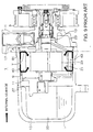
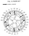
- FIG. 9 A longitudinal sectional view of a conventional vane rotary type gas compressor 1 used in an automotive air-conditioner or the like is shown in Fig. 9. Also, a cross-sectional view taken along the line A-A of Fig. 9 is shown in Fig. 10.
- a front head 5, a front side block 7, a cylinder 9, and a rear side block 11 are arranged in this order from a rotary transmission portion 3 side in the gas compressor 1. Also, a rotary shaft 13 is pivotally supported so as to penetrate the interior of the cylinder 9 and a rear cover 15 is provided.
- Compression chambers 21 are formed in the interior of the cylinder 9 for compressing refrigerant gas, and an intake chamber 23 for feeding the refrigerant gas into the compression chambers 21 is formed in the interior of an intake port 17 of the front head 5.
- a discharge chamber 25 for receiving the refrigerant gas compressed in the compression chambers 21 is formed in the interior of the rear cover 15, and a discharge port 27 is opened to the rear cover 15.
- An inner circumferential surface of the cylinder 9 is formed substantially into an elliptical shape in cross section.
- One end of the cylinder 9 is fastened and fixed in intimate contact with the front side block 7 and the other end is fastened and fixed in intimate contact with the rear side block 11 so that both ends of the cylinder 9 are closed to form the compression chambers 21 in its interior.
- a plurality of partitioning plate-like vanes 31... extending to both side blocks 7 and 11 are arranged substantially radially in the interior of the cylinder 9.
- Each vane 31... is fitted retractably and projectably in the radial direction to a groove 33a... of a rotor 33 formed on the rotary shaft 13.
- a hydraulic pressure is introduced into each groove 33a... of this rotor 33, and each vane 31... is biased in contact with the inner circumferential surface of the cylinder 9 by a centrifugal force generated upon the rotation and the hydraulic pressure.
- the interior of the cylinder 9 is partitioned into the plurality of compression chambers 21 by these vanes 31...
- a discharge port 35 for discharging the compressed refrigerant gas is caused to pass through a circumferential wall of the cylinder 9, and a cylinder cutaway portion 39 provided with a discharge valve 37 is formed on its outer side.
- an intake portion 41 for feeding the refrigerant gas into the interior of the cylinder 9, a hydraulic path 43 for lubricant oil, bolt holes 45 for fastening, and the like are formed in the axial direction of the cylinder.
- each vane 31... of the compression chambers 21 slides along the inner circumferential surface of the cylinder 9 so that the volume of the compression chamber 21 is changed in accordance with the change in its radius.
- the intake and the compression of the gas is performed by the change in volume.
- the sucked refrigerant gas is introduced from the intake chamber 23 in the interior of the front head 5 to the interior of the cylinder 9. Also, the compressed refrigerant gas is fed to the discharge chamber 25 in the interior of the rear cover 15 through the cylinder cutaway portion 39 in the outer circumferential portion of the cylinder 9 from the discharge port 35 of the cylinder 9.
- a clearance 40 is generated between the rear cover 15 and the cylinder 9 and this clearance 40 is in communication with the cylinder cutaway portion 39. Accordingly, in some cases, the refrigerant gas compressed in the cylinder 9 and kept at a high temperature and a high pressure is introduced into the compression chambers 21 or the intake portion 41, which are spaces at a lower pressure than that of the cylinder cutaway portion 39, through the cylinder cutaway portion 39 and the clearance 40 and further through a close contact portion between the cylinder 9 and both side blocks 7 and 11.
- the state of the internal leakage during this gas flow is shown by thick solid arrows in Figs. 9 and 10.
- the volumetric efficiency is degraded due to the resuction of the compressed gas and the compressive efficiency is degraded due to the elevation of the refrigerant gas temperature.
- the heat generation upon compression takes place in accordance with the elevation of the temperature of the refrigerant gas, which also leads to the oil film shortage in the sliding portion due to the degradation in viscosity of the lubricant oil.
- an object of the present invention is to provide a gas compressor in which the gas leakage from compression chambers of a cylinder is suppressed to thereby make it possible to enhance compressor characteristics such as a volumetric efficiency.
- a compressor is characterized by comprising a cylinder having a hollow portion opened at both ends and in which at least one compression chamber is formed in the hollow portion; two side blocks in intimate contact with both end faces of the cylinder for sealing both ends of the cylinder, respectively; a rear cover for storing the side block and the cylinder; and a first sealing means interposed in a close contact portion in which at least one of the two side blocks and the cylinder are brought into intimate contact with each other, in which the first seal means is arranged so as to surround an opening of the hollow portion.
- the first seal means is arranged so as to surround the opening of the hollow portion at the end surface of the cylinder, it is possible to prevent the flow back of the refrigerant gas from outside of the compression chamber or the cylinder to the lower pressure region between the inside and outside of the cylinder with the sealing means as a border.
- a compressor is characterized by including: a cylinder having a hollow portion opened at both ends and in which at least one compression chamber is formed in the hollow portion; an intake portion having an opening formed at an end surface of the cylinder for introducing refrigerant gas to the compression chamber; two side blocks in intimate contact with both end surfaces of the cylinder for sealing both ends of the cylinder, respectively; and a first seal means interposed in a close contact portion in which at least one of the two side blocks and the cylinder are brought into intimate contact with each other, in which the first seal means is arranged at a position so as to surround the opening of the hollow portion and to separate the opening of the intake portion and the opening of the hollow portion.
- the first seal means is interposed for separating the opening of the intake portion and the opening of the hollow portion in the close contact portion between the cylinder and the side block, the hollow portion is sealed separately from the intake portion. Accordingly, the refrigerant gas in the compression chamber may be sealed without being entrained in the intake portion.
- the compressor is characterized by including a second seal means for surrounding and sealing the opening of the intake portion.
- the intake portion may be sealed independently. Accordingly, even if the refrigerant gas leaks from the compression chamber, it is possible to prevent the gas from flowing into the intake portion,
- the compressor is characterized in that a cylinder cutaway portion for receiving the refrigerant gas discharged from the compression chamber is formed in an outer circumference of the cylinder and a fitting projecting portion for fitting the cylinder cutaway portion is formed in at least one of the two side blocks.
- the fitting projecting portion fitting the cylinder cutaway portion is formed in the side block, the refrigerant gas within the cylinder cutaway portion is sealed and prevented from leaking by the fitting projecting portion to thereby make it possible to secure the sealing performance.
- the compressor is characterized by including an inner contact projecting portion for intimately contacting the inner circumferential surface of the cylinder with at least one of the two side blocks, in which the first seal means is interposed in the close contact portion formed between the inner contact projecting portion and the inner circumferential surface of the cylinder.
- the first seal means is arranged for the cylinder inner circumferential surface through the inner contact projecting portion so that, even if it is impossible to obtain a sufficient space as the close contact portion in the cylinder end surface, it is possible to realize the seal function without fail.
- the compressor is characterized in that the first seal means or the second seal means is made of an elastic sealing member and the elastic seal member is fitted in a groove formed on one side of the two members facing each other at the close contact portion.
- seal member Since the seal member is provided so as to be fitted in the groove formed in the close contact portion, pressure seal may be performed by means of the elastic member having high sealing performance.
- the compressor is characterized in that the first seal means or the second seal means is formed of a thin plate-like gasket.
- the pressure seal of the close contact portion is possible by the gasket with a simple structure.
- a compressor is characterized by including a cylinder having a hollow portion opened at both ends and in which at least one compression chamber is formed in the hollow portion; and two side blocks in intimate contact with both end surfaces of the cylinder for sealing both ends of the cylinder, respectively, in which a cylinder cutaway portion for receiving the refrigerant gas discharged from the compression chamber is formed in a circumferential wall outer side portion of the cylinder, a fitting projecting portion for fitting the cylinder cutaway portion is formed in at least one of the two side block, a groove extending to the outer circumference of the fitting projecting portion or its proximal end is formed circumferentially in an outer circumferential edge of a close contact portion where the side block having the fitting projecting portion and the cylinder are brought into intimate contact with each other, and an elastic seal member is fitted in the groove.
- the outer circumferential seal may be applied by the fitting projecting portion fitting the cylinder cutaway portion. It is possible to easily seal the introduction of the refrigerant gas from the high pressure portion of the cylinder outer portion to the close contact portion by the outer circumferential seal.
- Fig. 1 is a perspective view of a cylinder of a gas compressor in accordance with a first embodiment of the present invention.
- Fig. 2 is a front view of a cylinder end face of Fig. 1.
- Fig. 3A to 3C are partial cross-sectional views showing a seal condition of the cylinder end face of Fig. 1.
- Fig. 4A to 4D are partial cross-sectional views showing the seal condition in an outer circumference of the cylinder end face of Fig. 1.
- Fig. 5A and 5B are cross-sectional views of structural examples at both ends of a cylinder of a gas compressor according to a second embodiment of the present invention.
- Fig. 6A and 6B are longitudinal sectional views in accordance with another structural example of Fig. 5.
- Fig. 7 is a perspective view of a cylinder of a gas compressor according to a third embodiment of the present invention.
- Fig. 8 is a perspective view of a front side block of a gas compressor according to a fourth embodiment of the present invention.
- Fig. 9 is a longitudinal sectional view (view showing the state of a gas leakage) of refrigerant a conventional vane rotary type gas compressor.
- Fig. 10 is a view (showing the state of the refrigerant gas leakage) taken along the line A-A of Fig. 9.
- FIG. 1 A perspective view of a cylinder 9 of a gas compressor according to a first embodiment of the present invention is shown in Fig. 1 and a front view illustrating an end surface 9a of the cylinder 9 shown in Fig. 1 is shown in Fig. 2. Note that, the same reference numerals are used to indicate the same components as those shown in Figs. 9 and 10 and the explanation thereof will be omitted.
- the end surface 9a of the cylinder 9 is formed into a circular shape, and a hollow portion 22 thereof is opened substantially in an elliptical shape. Cylinder cutaway portions 39 and 39 are partially formed in an outer circumferential portion of the cylinder 9.
- a seal member 51 is arranged in an elliptical shape so as to surround the opening of a hollow portion 22 in the end surface 9a of the cylinder 9, and is arranged at a position for separating the opening by intake portions 41 and the hollow portion 22 in the end surface 9a.
- the end face 9a of the cylinder 9 is brought into intimate contact with the end face of a front side block 7 or a rear side block 11. Then, the confronting surfaces of these two members are brought into intimate contact with each other to form a close contact portion.
- the hollow portion 22 of the cylinder 9 is sealed tightly between the thus constructed cylinder 9 and the front side block 7 by means of the seal member 51 provided at the end face 9a of the cylinder 9. Then, the intake portions 41 are positively separated from the hollow portion 22. Accordingly, the refrigerant gas of the compression chamber 21 is blocked just before the intake portions 41 and 41 by means of the seal member 51.
- a groove 53 having a rectangular cross-section is formed in elliptical shape in the end face of the cylinder 9 of Fig. 3A and an elastic seal member 55 such as an O-ring is fitted in this groove 53.
- the front side block 7 is brought into intimate contact with this seal member 55 so as to press it.
- a groove 53 facing the end face of the cylinder 9 is formed in the front side block 7 and the seal member 55 is fitted in this groove 53.
- Fig. 3C shows a case where a gasket 57 is interposed between the cylinder 9 and the front side block 7.
- the elastic seal member 55 is fitted into the groove 53 formed in the end face of the cylinder 9 or in the member with which the seal member is brought in contact, thereby making it possible to attain the pressure seal by the elastic member 55 that has a good sealing performance.
- FIG. 4A to 4D Cross-sectional views showing the seal condition in the outer circumferential portions of the cylinder end face of Fig. 1 are shown in Figs. 4A to 4D.
- the groove 54 having a rectangular cross section of Fig. 54A is formed by means of a rectangular cutaway of the end face outer circumferential portion of the cylinder 9 and the front side block 7.
- a triangular cross-sectional groove 54a of Fig. 4B is formed by means of a bevel cutaway of the end face circumferential portion of the cylinder 9 and the front side block 7.
- the elastic seal members 55 such as O-rings are fitted in these grooves 54 and 54a.
- the groove 54 having a rectangular cross section of Fig. 4C is formed by means of a rectangular cutaway of the end face outer circumferential portion of the front side block 7 and the cylinder 9.
- a triangular cross-sectional groove 54a of Fig. 4D is formed by means of a bevel cutaway of the end face circumferential portion of the front side block 7 and the cylinder 9.
- the elastic seal members 55 such as O-rings are fitted in these grooves 54 and 54a.
- An outer circumferential seal is formed for sealing the close contact portion on the outer circumferential surface of the side block 7 and the cylinder 9 which are in intimate contact with each other, by the rectangular cutaway groove 54 or the beveled groove 54a.
- the outer circumferential seal may prevent the refrigerant gas from entering into the close contact portion from the high pressure region of the outer portion of the cylinder 9 by means of the simple structure in with the open groove is opened to the outer circumferential side. Accordingly, it is possible to prevent the flow back of the refrigerant gas from the high pressure portion to the low pressure region of the hollow portion 22 and the intake portions 41.
- FIG. 5A and 5B Cross-sectional views of structural examples of both ends of the cylinder 9 of the compressor according to the second embodiment of the present invention are shown in Figs. 5A and 5B and Figs. 6A and 6B.
- the same refcrence numerals are used to indicate the same components as those in Fig. 3 and the explanation thereof will be omitted.
- An inner contact projecting portion 61 of which is elliptical shaped internally contacting with the inner circumferential surface of the cylinder 9 is provided in the front side block 7 and the elastic seal member 55 is interposed between this inner contact projecting portion 61 and the inner circumferential surface of the cylinder 9.
- an inner contact projecting portion 63 internally contacting with the inner circumferential surface of the cylinder 9 is provided in the rear side block 11 and an elastic seal member 55 is interposed between this inner contact projecting portion 63 and the inner circumferential surface of the cylinder 9.
- Fig. 5A shows an example in which a groove 53 is formed in the circumferential surface of the inner contact projecting portion 61 of the front side block 7, an elastic seal member 55 is fitted therein, and in the same manner, a groove 53 is formed in the outer circumferential surface of the inner contact projecting portion 63 of the rear side block 11 and an elastic seal member 55 is fitted therein.
- Fig, 5B shows an example in which a triangular groove 53a is formed instead of the groove 53 having a rectangular cross-section.
- Fig. 6A shows an example in which a groove 53 is formed at a position facing the outer circumferential surface of the inner contact projecting portion 61, of the front side block 7 in the inner circumferential surface of the cylinder 9 and an elastic seal member 55 is fitted in this groove 53.
- a groove 53 is formed in the outer circumferential surface of the inner contact projecting portion 63 and an elastic seal member 55 is fitted therein.
- Fig. 6B shows an example in which a triangular groove 53a is formed instead of the groove 53 having a rectangular cross-section.
- FIG. 7 A perspective view of a cylinder 70 of a gas compressor in accordance with the third embodiment of the present invention is shown in Fig. 7. Note that, the same reference numerals are used to indicate the same components as those shown in Figs. 1, 2, 9 and 10 and the explanation thereof will be omitted.
- cylinder cutaway portions 39 and 39 are formed at positions opposite to each other in the outer circumferential portion of the cylinder 70.
- the intake portions 41 and 41 penetrate in the longitudinal direction of the cylinder 70 and are opened to both end faces 70a and 70a adjacent to the cylinder cutaway portions 39 and 39.
- the seal member 51 is provided so as to surround the opening of the hollow portion 22 in the end face 70a of the cylinder 70, and in addition, seal members 71 and 71 are arranged integrally to surround the openings of the intake portions 41 and 41. In the case where there is a sufficient space in the end face 70a, each seal member 51 and 71 may be provided separately. In the same manner, in the other end face that will become the lower surface of the cylinder 70 in the drawing, the seal members 51 and 71 are arranged to surround the respective intake portions 41 and 41 of the hollow portion 22.
- the front side block 7 is brought into intimate contact with the end face 70a of the cylinder 70 so that the hollow portion 22 and the intake portions 41 and 41 are sealed independently by the seal member 51 and the seal members 71 and 71, respectively.
- FIG. 8 A perspective view of the front side block 7 of a gas compressor according to the fourth embodiment of the present invention is shown in Fig. 8.
- the same reference numerals are used to indicate the same components as those in Fig. 9 and the explanation thereof will be omitted.
- fitting projecting portions 73 and 73 are formed for fitting the cylinder cutaway portions 39 and 39 of the cylinder 70 of Fig. 7 in the end face 7a of the front side block 7.
- the two fitting projecting portions 73 and 73 are formed corresponding to the cylinder cutaway portions 39 and 39 in the rear side block 11 (not shown).
- the front side block 7 covers from above one of the end faces 70a of the cylinder 70 such that they come into intimate contact with each other and the fitting projecting portions 73 and 73 of the front side block 7 are fitted with the cylinder cutaway portions 39 and 39 opened to the end face 70a of the cylinder 70.
- the gas leakage from the cylinder cutaway portions 39 and 39 is prevented by the seal effect by the fitting projecting portions 73 and 73. Accordingly, it is possible to prevent the entrainment from the cylinder cutaway portions 39 and 39 side to the intake portions 41 and 41. This also applies for the case in the rear side block 11 side.
- the grooves may be formed in the circumferential direction along the close contact portion on the outer circumferential surface at which the cylinder 70 and the side blocks 7 and 11 are in intimate contact with each other.
- the elastic seal member is fitted in the groove to thereby make it possible to form the above-described outer circumferential seal of Fig. 4. It is possible to easily seal the flow of the refrigerant gas from the high pressure region of the outer portion of the cylinder 70 to the close contact portion by this outer seal.
- seal members 71 and 71 for the intake portions 41 and 41 and the seal member 51 for the hollow portion 22 of Fig. 7 in accordance with the third embodiment are used together so that the entrainment of the refrigerant gas due to the gas leakage to the intake side may be further effectively prevented.
- the entrainment of the refrigerant gas to the compression chambers 21 or the intake portions 41 and 41 is prevented to thereby make it possible to prevent the degradation of the volumetric efficiency due to the resuction of the compressed gas and the degradation of the compressive efficiency due to the elevation of the refrigerant gas.
- the mixture of the refrigerant gas accompanied with the increase of the heat generation upon the compression is prevented to thereby make it possible to prevent the oil film shortage or the like of the sliding portion due to the degradation in viscosity of the lubricant oil.
- the gas compressor according to the present invention it is possible to enhance the compressor characteristics such as COP (that is an evaluation coefficient representing the compressor ability by a ratio of the cooling ability to the power) .
- COP that is an evaluation coefficient representing the compressor ability by a ratio of the cooling ability to the power
- a single O-ring 81 is embedded in the circumferential direction in the groove surrounded by the rear cover 15, the front head 5 and the front side block 7. Then, each surface portion of the front side block 7, the front head 5 and the rear cover 15 contacting the O-ring 81 is machined with a high precision (surface roughness of 6.3Z in terms of JIS ten point average roughness) for positively maintaining the sealing performance with respect to the outside.
- the cylinder 9, the front side block 7 and the rear side block 11 are formed into the shell structure covered by the rear cover 15, and the sealing performance with respect to the outside is maintained by means of only the O-ring 81 and each surface portion of the front side block 7, the front head 5 and the rear cover 15 contacting with the O-ring 81.
- the surface roughness of the surface portion 7a of the front side block 7 to be brought into contact with the right end face of the gasket 57 and the surface portion 9a of the cylinder 9 to be brought into contact with the left end face of the gasket 57 maybe 12.5Z in terms of JIS ten point average roughness.
- the machining of each surface of the circumferential walls 61a and 63a of the inner contact projecting portions 61 and 63 of the side blocks 7 and 11 and the inner wall 53b of the groove 53 having the rectangular cross-section contacting with the elastic seal member 55 may be performed also at the surface roughness of 12.5Z in terms of JIS ten point average roughness.
- the machining of the metal surface portion that is to be brought into contact with the seal member arranged in the shell structure internal portion is easy and may be structured at low cost.
- the seal means are interposed between the end face of the cylinder and the two side blocks separately for the hollow portion and the intake portions, it is possible to seal the hollow portion of the cylinder and to positively separate the intake portions away from the hollow portion side.
- the gas compressor according to the present invention it is possible to suppress the gas leakage of the refrigerant gas medium to thereby enhance the compressor characteristics such as volumetric efficiency.
Landscapes
- Engineering & Computer Science (AREA)
- Mechanical Engineering (AREA)
- General Engineering & Computer Science (AREA)
- Rotary Pumps (AREA)
- Applications Or Details Of Rotary Compressors (AREA)
- Compressor (AREA)
Applications Claiming Priority (4)
| Application Number | Priority Date | Filing Date | Title |
|---|---|---|---|
| JP2001244038 | 2001-08-10 | ||
| JP2001244038 | 2001-08-10 | ||
| JP2002216550 | 2002-07-25 | ||
| JP2002216550A JP4104391B2 (ja) | 2001-08-10 | 2002-07-25 | 気体圧縮機 |
Publications (2)
| Publication Number | Publication Date |
|---|---|
| EP1283367A2 true EP1283367A2 (de) | 2003-02-12 |
| EP1283367A3 EP1283367A3 (de) | 2003-05-28 |
Family
ID=26620388
Family Applications (1)
| Application Number | Title | Priority Date | Filing Date |
|---|---|---|---|
| EP02255530A Withdrawn EP1283367A3 (de) | 2001-08-10 | 2002-08-07 | Flügelzellenverdichter |
Country Status (4)
| Country | Link |
|---|---|
| US (1) | US20030031577A1 (de) |
| EP (1) | EP1283367A3 (de) |
| JP (1) | JP4104391B2 (de) |
| CN (1) | CN1273745C (de) |
Families Citing this family (2)
| Publication number | Priority date | Publication date | Assignee | Title |
|---|---|---|---|---|
| US8793895B2 (en) | 2006-02-10 | 2014-08-05 | Praxair Technology, Inc. | Lyophilization system and method |
| US9835156B2 (en) | 2012-01-12 | 2017-12-05 | Carrier Corporation | Sealing arrangement for semi-hermetic compressor |
Family Cites Families (18)
| Publication number | Priority date | Publication date | Assignee | Title |
|---|---|---|---|---|
| US3193190A (en) * | 1965-07-06 | Lindberg vacuum pump | ||
| US1722616A (en) * | 1926-06-18 | 1929-07-30 | Edward T Williams | Compressor |
| GB2088959A (en) * | 1980-12-09 | 1982-06-16 | Atsugi Motor Parts Co Ltd | Rotary Positive-displacement Fluid-machine |
| JPS631030Y2 (de) * | 1981-04-06 | 1988-01-12 | ||
| JPS59180090A (ja) * | 1983-03-30 | 1984-10-12 | Atsugi Motor Parts Co Ltd | ベ−ンポンプ |
| DE3616515A1 (de) * | 1986-05-16 | 1987-11-19 | Mugioiu Dipl Ing Ioan | Drehschiebervakuumpumpe |
| JPH01208594A (ja) * | 1988-02-10 | 1989-08-22 | Diesel Kiki Co Ltd | 圧縮機のシール構造並びに該構造に用いるシール |
| US5123333A (en) * | 1990-10-29 | 1992-06-23 | Sollami Phillip A | Seals for housing of a rotary actuator |
| US5083909A (en) * | 1990-11-29 | 1992-01-28 | The United States Of America As Represented By The Secretary Of The Navy | Seawater hydraulic vane type pump |
| FR2692941A1 (fr) * | 1992-06-30 | 1993-12-31 | Sergent Andre | Pompe à palettes pour produits alimentaires. |
| JPH0712072A (ja) * | 1993-06-23 | 1995-01-17 | Toyota Autom Loom Works Ltd | ベーン圧縮機 |
| FR2708051B1 (fr) * | 1993-07-23 | 1995-10-13 | Ifremer | Actionneur rotatif commandé par fluide. |
| JPH0988845A (ja) * | 1995-09-29 | 1997-03-31 | Unisia Jecs Corp | ベーンポンプ |
| JPH09158868A (ja) * | 1995-12-08 | 1997-06-17 | Zexel Corp | ベーン型圧縮機 |
| JPH09317670A (ja) * | 1996-05-27 | 1997-12-09 | Zexel Corp | ベーン型圧縮機 |
| JPH109166A (ja) * | 1996-06-18 | 1998-01-13 | Zexel Corp | ベーン型圧縮機 |
| US5876192A (en) * | 1996-11-08 | 1999-03-02 | Ford Global Technologies, Inc. | Differential expansion control assembly for a pump |
| JPH11303781A (ja) * | 1998-04-20 | 1999-11-02 | Zexel:Kk | ベーン型圧縮機 |
-
2002
- 2002-07-25 JP JP2002216550A patent/JP4104391B2/ja not_active Expired - Fee Related
- 2002-08-07 EP EP02255530A patent/EP1283367A3/de not_active Withdrawn
- 2002-08-09 US US10/216,415 patent/US20030031577A1/en not_active Abandoned
- 2002-08-10 CN CNB021437602A patent/CN1273745C/zh not_active Expired - Fee Related
Also Published As
| Publication number | Publication date |
|---|---|
| CN1409012A (zh) | 2003-04-09 |
| JP4104391B2 (ja) | 2008-06-18 |
| EP1283367A3 (de) | 2003-05-28 |
| CN1273745C (zh) | 2006-09-06 |
| JP2003129980A (ja) | 2003-05-08 |
| US20030031577A1 (en) | 2003-02-13 |
Similar Documents
| Publication | Publication Date | Title |
|---|---|---|
| US5921756A (en) | Swash plate compressor including double-headed pistons having piston sections with different cross-sectional areas | |
| US5509793A (en) | Rotary device with slidable vane supports | |
| KR900003715B1 (ko) | 베인형 회전압축기 | |
| US4101250A (en) | Swash plate type compressor | |
| CN110778498B (zh) | 压缩机及制冷设备 | |
| KR20070083469A (ko) | 스크류 압축기 시일 | |
| JP6428200B2 (ja) | 電動圧縮機 | |
| EP4047209A1 (de) | Verdichter und kühlgerät | |
| KR20070049969A (ko) | 로터리 압축기 | |
| EP1283367A2 (de) | Flügelzellenverdichter | |
| EP1236903A2 (de) | Vakuumpumpe mit Wellendichtmitteln | |
| US6663367B2 (en) | Shaft seal structure of vacuum pumps | |
| US6659747B2 (en) | Shaft seal structure of vacuum pumps | |
| JPH1026077A (ja) | 両頭ピストン式圧縮機 | |
| US4101249A (en) | Swash plate type compressor | |
| EP0838593B1 (de) | Flügelzellenverdichter | |
| US6186759B1 (en) | Helical blade type compressor and a refrigeration cycle apparatus using the same | |
| US6945759B2 (en) | Engine driven dry air pump with a flange mounted oil drain | |
| KR200392423Y1 (ko) | 복식 로터리 압축기의 실링구조 | |
| US3915599A (en) | Structure for preventing leakage of lubricating oil in rotary-piston internal combustion engines | |
| JP3745915B2 (ja) | 気体圧縮機 | |
| EP0531718B1 (de) | Taumelscheibenverdichter | |
| KR100450104B1 (ko) | 진공펌프의 축밀봉구조 | |
| JP2007092710A (ja) | 気体圧縮機 | |
| EP2857688A1 (de) | Rotationsverdichter |
Legal Events
| Date | Code | Title | Description |
|---|---|---|---|
| PUAI | Public reference made under article 153(3) epc to a published international application that has entered the european phase |
Free format text: ORIGINAL CODE: 0009012 |
|
| AK | Designated contracting states |
Designated state(s): AT BE BG CH CY CZ DE DK EE ES FI FR GB GR IE IT LI LU MC NL PT SE SK TR |
|
| AX | Request for extension of the european patent |
Extension state: AL LT LV MK RO SI |
|
| PUAL | Search report despatched |
Free format text: ORIGINAL CODE: 0009013 |
|
| AK | Designated contracting states |
Designated state(s): AT BE BG CH CY CZ DE DK EE ES FI FR GB GR IE IT LI LU MC NL PT SE SK TR |
|
| AX | Request for extension of the european patent |
Extension state: AL LT LV MK RO SI |
|
| 17P | Request for examination filed |
Effective date: 20031027 |
|
| AKX | Designation fees paid |
Designated state(s): DE FR GB |
|
| 17Q | First examination report despatched |
Effective date: 20040310 |
|
| RAP1 | Party data changed (applicant data changed or rights of an application transferred) |
Owner name: CALSONIC COMPRESSOR MANUFACTURING INC. |
|
| STAA | Information on the status of an ep patent application or granted ep patent |
Free format text: STATUS: THE APPLICATION IS DEEMED TO BE WITHDRAWN |
|
| 18D | Application deemed to be withdrawn |
Effective date: 20040721 |