EP1283097A2 - Manufacturing of powdered material - Google Patents
Manufacturing of powdered material Download PDFInfo
- Publication number
- EP1283097A2 EP1283097A2 EP02023590A EP02023590A EP1283097A2 EP 1283097 A2 EP1283097 A2 EP 1283097A2 EP 02023590 A EP02023590 A EP 02023590A EP 02023590 A EP02023590 A EP 02023590A EP 1283097 A2 EP1283097 A2 EP 1283097A2
- Authority
- EP
- European Patent Office
- Prior art keywords
- pressing
- powders
- anyone
- advancing
- conveyor means
- Prior art date
- Legal status (The legal status is an assumption and is not a legal conclusion. Google has not performed a legal analysis and makes no representation as to the accuracy of the status listed.)
- Granted
Links
Images


Classifications
-
- B—PERFORMING OPERATIONS; TRANSPORTING
- B30—PRESSES
- B30B—PRESSES IN GENERAL
- B30B5/00—Presses characterised by the use of pressing means other than those mentioned in the preceding groups
- B30B5/04—Presses characterised by the use of pressing means other than those mentioned in the preceding groups wherein the pressing means is in the form of an endless band
-
- B—PERFORMING OPERATIONS; TRANSPORTING
- B28—WORKING CEMENT, CLAY, OR STONE
- B28B—SHAPING CLAY OR OTHER CERAMIC COMPOSITIONS; SHAPING SLAG; SHAPING MIXTURES CONTAINING CEMENTITIOUS MATERIAL, e.g. PLASTER
- B28B1/00—Producing shaped prefabricated articles from the material
- B28B1/005—Devices or processes for obtaining articles having a marble appearance
-
- B—PERFORMING OPERATIONS; TRANSPORTING
- B28—WORKING CEMENT, CLAY, OR STONE
- B28B—SHAPING CLAY OR OTHER CERAMIC COMPOSITIONS; SHAPING SLAG; SHAPING MIXTURES CONTAINING CEMENTITIOUS MATERIAL, e.g. PLASTER
- B28B1/00—Producing shaped prefabricated articles from the material
- B28B1/008—Producing shaped prefabricated articles from the material made from two or more materials having different characteristics or properties
-
- B—PERFORMING OPERATIONS; TRANSPORTING
- B28—WORKING CEMENT, CLAY, OR STONE
- B28B—SHAPING CLAY OR OTHER CERAMIC COMPOSITIONS; SHAPING SLAG; SHAPING MIXTURES CONTAINING CEMENTITIOUS MATERIAL, e.g. PLASTER
- B28B1/00—Producing shaped prefabricated articles from the material
- B28B1/08—Producing shaped prefabricated articles from the material by vibrating or jolting
- B28B1/10—Producing shaped prefabricated articles from the material by vibrating or jolting and applying pressure otherwise than by the use of presses
-
- B—PERFORMING OPERATIONS; TRANSPORTING
- B28—WORKING CEMENT, CLAY, OR STONE
- B28B—SHAPING CLAY OR OTHER CERAMIC COMPOSITIONS; SHAPING SLAG; SHAPING MIXTURES CONTAINING CEMENTITIOUS MATERIAL, e.g. PLASTER
- B28B1/00—Producing shaped prefabricated articles from the material
- B28B1/14—Producing shaped prefabricated articles from the material by simple casting, the material being neither forcibly fed nor positively compacted
- B28B1/16—Producing shaped prefabricated articles from the material by simple casting, the material being neither forcibly fed nor positively compacted for producing layered articles
-
- B—PERFORMING OPERATIONS; TRANSPORTING
- B28—WORKING CEMENT, CLAY, OR STONE
- B28B—SHAPING CLAY OR OTHER CERAMIC COMPOSITIONS; SHAPING SLAG; SHAPING MIXTURES CONTAINING CEMENTITIOUS MATERIAL, e.g. PLASTER
- B28B11/00—Apparatus or processes for treating or working the shaped or preshaped articles
- B28B11/14—Apparatus or processes for treating or working the shaped or preshaped articles for dividing shaped articles by cutting
-
- B—PERFORMING OPERATIONS; TRANSPORTING
- B28—WORKING CEMENT, CLAY, OR STONE
- B28B—SHAPING CLAY OR OTHER CERAMIC COMPOSITIONS; SHAPING SLAG; SHAPING MIXTURES CONTAINING CEMENTITIOUS MATERIAL, e.g. PLASTER
- B28B13/00—Feeding the unshaped material to moulds or apparatus for producing shaped articles; Discharging shaped articles from such moulds or apparatus
- B28B13/02—Feeding the unshaped material to moulds or apparatus for producing shaped articles
- B28B13/0205—Feeding the unshaped material to moulds or apparatus for producing shaped articles supplied to the moulding device in form of a coherent mass of material, e.g. a lump or an already partially preshaped tablet, pastil or the like
-
- B—PERFORMING OPERATIONS; TRANSPORTING
- B28—WORKING CEMENT, CLAY, OR STONE
- B28B—SHAPING CLAY OR OTHER CERAMIC COMPOSITIONS; SHAPING SLAG; SHAPING MIXTURES CONTAINING CEMENTITIOUS MATERIAL, e.g. PLASTER
- B28B13/00—Feeding the unshaped material to moulds or apparatus for producing shaped articles; Discharging shaped articles from such moulds or apparatus
- B28B13/02—Feeding the unshaped material to moulds or apparatus for producing shaped articles
- B28B13/0215—Feeding the moulding material in measured quantities from a container or silo
- B28B13/022—Feeding several successive layers, optionally of different materials
-
- B—PERFORMING OPERATIONS; TRANSPORTING
- B28—WORKING CEMENT, CLAY, OR STONE
- B28B—SHAPING CLAY OR OTHER CERAMIC COMPOSITIONS; SHAPING SLAG; SHAPING MIXTURES CONTAINING CEMENTITIOUS MATERIAL, e.g. PLASTER
- B28B13/00—Feeding the unshaped material to moulds or apparatus for producing shaped articles; Discharging shaped articles from such moulds or apparatus
- B28B13/02—Feeding the unshaped material to moulds or apparatus for producing shaped articles
- B28B13/0215—Feeding the moulding material in measured quantities from a container or silo
- B28B13/027—Feeding the moulding material in measured quantities from a container or silo by using a removable belt or conveyor transferring the moulding material to the moulding cavities
-
- B—PERFORMING OPERATIONS; TRANSPORTING
- B28—WORKING CEMENT, CLAY, OR STONE
- B28B—SHAPING CLAY OR OTHER CERAMIC COMPOSITIONS; SHAPING SLAG; SHAPING MIXTURES CONTAINING CEMENTITIOUS MATERIAL, e.g. PLASTER
- B28B13/00—Feeding the unshaped material to moulds or apparatus for producing shaped articles; Discharging shaped articles from such moulds or apparatus
- B28B13/02—Feeding the unshaped material to moulds or apparatus for producing shaped articles
- B28B13/0295—Treating the surface of the fed layer, e.g. removing material or equalization of the surface
-
- B—PERFORMING OPERATIONS; TRANSPORTING
- B28—WORKING CEMENT, CLAY, OR STONE
- B28B—SHAPING CLAY OR OTHER CERAMIC COMPOSITIONS; SHAPING SLAG; SHAPING MIXTURES CONTAINING CEMENTITIOUS MATERIAL, e.g. PLASTER
- B28B13/00—Feeding the unshaped material to moulds or apparatus for producing shaped articles; Discharging shaped articles from such moulds or apparatus
- B28B13/04—Discharging the shaped articles
- B28B13/06—Removing the shaped articles from moulds
-
- B—PERFORMING OPERATIONS; TRANSPORTING
- B28—WORKING CEMENT, CLAY, OR STONE
- B28B—SHAPING CLAY OR OTHER CERAMIC COMPOSITIONS; SHAPING SLAG; SHAPING MIXTURES CONTAINING CEMENTITIOUS MATERIAL, e.g. PLASTER
- B28B3/00—Producing shaped articles from the material by using presses; Presses specially adapted therefor
- B28B3/003—Pressing by means acting upon the material via flexible mould wall parts, e.g. by means of inflatable cores, isostatic presses
-
- B—PERFORMING OPERATIONS; TRANSPORTING
- B28—WORKING CEMENT, CLAY, OR STONE
- B28B—SHAPING CLAY OR OTHER CERAMIC COMPOSITIONS; SHAPING SLAG; SHAPING MIXTURES CONTAINING CEMENTITIOUS MATERIAL, e.g. PLASTER
- B28B3/00—Producing shaped articles from the material by using presses; Presses specially adapted therefor
- B28B3/02—Producing shaped articles from the material by using presses; Presses specially adapted therefor wherein a ram exerts pressure on the material in a moulding space; Ram heads of special form
-
- B—PERFORMING OPERATIONS; TRANSPORTING
- B28—WORKING CEMENT, CLAY, OR STONE
- B28B—SHAPING CLAY OR OTHER CERAMIC COMPOSITIONS; SHAPING SLAG; SHAPING MIXTURES CONTAINING CEMENTITIOUS MATERIAL, e.g. PLASTER
- B28B3/00—Producing shaped articles from the material by using presses; Presses specially adapted therefor
- B28B3/12—Producing shaped articles from the material by using presses; Presses specially adapted therefor wherein one or more rollers exert pressure on the material
- B28B3/123—Producing shaped articles from the material by using presses; Presses specially adapted therefor wherein one or more rollers exert pressure on the material on material in moulds or on moulding surfaces moving continuously underneath or between the rollers, e.g. on an endless belt
-
- B—PERFORMING OPERATIONS; TRANSPORTING
- B28—WORKING CEMENT, CLAY, OR STONE
- B28B—SHAPING CLAY OR OTHER CERAMIC COMPOSITIONS; SHAPING SLAG; SHAPING MIXTURES CONTAINING CEMENTITIOUS MATERIAL, e.g. PLASTER
- B28B5/00—Producing shaped articles from the material in moulds or on moulding surfaces, carried or formed by, in, or on conveyors irrespective of the manner of shaping
- B28B5/02—Producing shaped articles from the material in moulds or on moulding surfaces, carried or formed by, in, or on conveyors irrespective of the manner of shaping on conveyors of the endless-belt or chain type
Definitions
- the present invention concerns a system for manufacturing powder material, in particular for the production of ceramic tiles.
- PCT/EP95/04560 describes a system for pressing ceramic tiles, wherein a continuous strip of powders having a predetermined thickness and width is formed, predetermined areas of said strip being compacted to obtain tiles, or pre-compacted semimanufactured products which are precursors of the tiles to be formed. In the latter case there is provided pressing of semimanufactured products in a die to obtain corresponding tiles ready to be subsequently dried and fired.
- US-A-3,540,093 describes an apparatus for manufacturing ceramic tiles, having substantially uniform compactness, homogeneity, density and thickness, wherein from a bottom end of a hopper, in which powders of ceramic material are contained, a vertical strip of compacted powders is formed by action of opposed pressing rolls, from said strip some pre-compacted products being subsequently severed by cutting and distributed on a horizontal conveyor from which the severed products are transferred to a die to obtain tile bodies.
- GB-A-880,892 describes an apparatus for forming clay material in which a mass of clay, humidified in such a way as to result at a plastic state, is laminated between a pair of rolls to obtain a layer of plastic material and subsequently the layer is formed by a forming die, without substantial alteration of the volume, in such a way as to obtain a plurality of tiles interconnected by webs which are subsequently cut by rotating disks.
- Prior art comprises also some apparatuses for making tiles in which powders are distributed in two superimposed layers during distinct strokes of a distributing trolley or distinct phases of the same stroke of a distributing trolley, the trolley being generally provided with grids and each one leading the powders of a determined layer at the matrix of the press.
- An example of such a kind of apparatuses is described in IT-A-1,069,458.
- An object of the present invention is to improve the existent apparatuses for working ceramic tiles.
- a method for pressing powdered material to obtain tiles comprising the steps of:
- apparatus for pressing powdered material in such a way as to obtain tiles comprising flexible conveyor means for receiving powders thereon from distributing means and for advancing said powders along an advancing direction through a pressing station, containing means for laterally containing said powders on said conveyor means, said containing means being distinct from said powdered material, means for pressing said powders while advancing through said pressing station, characterized in that said side containing means are arranged to act on the powders to be pressed during said advancing and said pressing of the powders.
- forming means for forming ceramic material comprising moving means arranged to move, along a reciprocal approaching direction, powders to be pressed and pressing means to decrease significantly the volume of said powders, the pressing means being arranged to press said powders along a pressing direction transversally disposed with respect to said approaching direction, characterized in that said pressing means are conformed to act on said powders with pressing intensity which increases along said approaching direction.
- said pressing means comprises continuous pressing means, as rotating bodies, arranged to progressively press powders while said material advances.
- the pressing means comprises swinging pressing means disposed along the approaching direction.
- continuous pressing means acting on a horizontal strip of powders allows to significantly reduce the width of the areas of the strip of powders to be pressed and furthermore to limit scrap material.
- the forming of a continuous strip of pressed material renders possible feeding of the mould without using particular conveyor means: in fact the pressed strip may be advanced toward the mould by the action of pressing means acting on the belt conveyor means.
- the continuous pressing means may comprise rolls, belt conveyor means, swinging orbital elements and others.
- powders 1 are contained in hopper distributing means 2 having an outlet section controlled by a dosing squegee 2a, which is adjustable in height and faces with a horizontal upper part of belt conveyor means 3, advancing the powders to be pressed at a press with mould means 4 for ceramic tiles 5 ( Figure 4), in such a way as to form a strip 6, or main layer, of powders.
- distributing decorating means 7 may be interposed to pour on the strip 6 a decorating layer 8, the decorating means possibly comprising further hopper means 9 containing a decorating granular material 10, having the outlet section facing the strip 6 and controlled by a rotating dosing roll 11.
- the belt conveyor means 3 is partially rolled up on a roll 12 which defines an end of the belt conveyor means near to the mould 4, rotating about a first, substantially horizontal axis A, defining a vertical plane whereon, above the strip 6, a second axis B lies around which a second pressing roll 13 for pressing powders 6, 8 is rotatable.
- the strip of powders 6, 8 which passes on the belt conveyor means 3 between the rolls 12 and 13 is compacted to a greater or lower extent depending on the distance between the axes A and B, in such a way as to obtain, at the exit of the rolls 12, 13, from powders forming the strip 6, 8, a compacted layer 14, which is coherent, i.e.
- the mould means 4 are provided with lower frame means 16, substantially complanate with the transferring plane 15, and defining a lower cavity 17 ( Figure 2) arranged to contain longitudinally consecutive portions of layer 14 of compacted powders and to allow their pressing between a punch 18 and a bottom portion 19 of the mould means 4.
- Advancing of the compacted layer 14 is controlled by the motion of the rolls 12 and 13: thus, at the end of the pressing cycle, the layer 14 is advanced by the said rolls until the elimination, from the pressing area, of scrap materials 20 which may be collected by a crusher 21 and introduced again into the process as powders.
- the diameter of the rolls 12 and 13 has to be sufficiently large so that the rolls are sufficiently resistant to flexing during pressing and define a pressing sector C having suitable width.
- the width of the sector corresponds to the angle C of incidence defined between the tangent to the roll in the contact area at the entry of the powders and a direction parallel to the plane of the strip: to be successful the angle C of incidence should be suitably low.
- a pressing cycle comprises the following phases:
- the pressing cycle comprises the phases 1) and 3) as defined above, and the phases 2a) and 4a) described below:
- the lowering of the lower frame means 16 takes place together with the lowering of the moving plane 15, and, preferably, the belt conveyor means 3 with respective rolls 12 and 13, in the direction shown by the arrow F.
- Figures 15 and 16 show the use of a mould such as that shown in Figures 5 to 8 to obtain a tile 5 having a spacing portion 25 of greater dimension and a front face 26 formed above.
- Figure 9 shows that, in addition to the rolls 12 and 13, there may be provided further upper rolls 29 and lower rolls, parallel to each other and to rolls 12 and 13, the centrelines distance between the further upper rolls 29 and the corresponding further lower rolls 30 being progressively increasing moving away from the rolls 12 and 13 in such a way as to allow a more gradual compacting of the powders 6.
- the angle C of incidence is conveniently small for each upper rolls 29, so as to decrease the risk of heterogeneities in compactation which would arise from longitudinal movings of the powders.
- Figure 12 shows that on the plurality of upper pressing rolls 13, 29 compacting belt means 31 are peripherally rolled up to render more homogeneous and progressive the compacting of the powders.
- the compacting belt means 31 allow to define carefully a predetermined value of the angle of incidence C and allow to exert on the powders 6, 8 a particularly gradual action.
- Figures 13 and 18 show that the end area of the belt.
- conveyor means 3 and the transferring plane 15 next thereto may be hinged by a transversal axis Z passing through the strip of powders 6, before the area of beginning of compacting, in such a way as to allow the compacted material 14 to follow the lowering and the lifting of the transferring plane 15 and of the lower frame means 16 in the phases of the pressing cycle described referring to Figures 5 to 8.
- the upper compacting belt means 31 must be free to rotate about the axis Z of a relatively wide angular sector.
- Figure 18 shows that the lower frame means 16a may be open towards the moving plane 15, in such a way as to surround the bottom 19 only in three side, so as to limit the discharged material.
- the areas of the layer of compacted material 14, which are subjected to the action of the upper frame means 23, cause an interruption of the continuity of such a layer; when the moving plane 15, rotating about the axis Z, goes down with respect to the bottom 19, its edge nearest to the bottom 19 is no longer complanate thereto and thus only the portion 35 of the layer of compacted material 14, which are not subjected to the action of the frame means 23 and of the punch 18, are severed from the layer 14 along a fracture line Y.
- the belt conveyor means 3 may be provided with projections acting as longitudinal severing means 36 for severing powders 6, said severing means being received into respective recess means 38 of the pressing rolls 13, 29, and with lateral containing means 37, or side-walls, in such a way as to obtain two parallel layers 14a of compacted material from two respective layers 6a of powdered material.
- the recess means 38 may define pressing means 38a arranged to keep pressed, and, as a consequence, larger than their initial dimensions, the longitudinal severing means 36 and the lateral containing means 37 during pressing. This decreases the possibility of undesired moving of the severing means during pressing. Moreover, this supports the delivery of the pressed products 14 because, when the action of the pressing means 38a finishes, the longitudinal severing means 36 and the lateral containing means 37 assume again their initial dimensions, so detaching from the pressed products.
- lateral control means 39 limiting the deformations of the lateral containing means 37 during pressing, the lateral control means 39 advantageously comprising some rolls having vertical axes interacting with the lateral containing means 37 to avoid said lateral containing means 37 deforming outwardly during pressing.
- the lateral containing means 37 define side walls having wide-apart shape toward the outside of the belt conveyor means 3 in such a way as to support the delivering of the layer 14, 14a.
- the severing means 36 and the lateral containing means 37 may be made in elastic material in such a way as to be able to lengthen in the rolling on the rolls of the end of the belt conveyor means 3.
- the containing means are made in elastomeric material. This further supports the delivering of the compacted material 14 from the side of the mould 4.
- the entire group defined by the front end of the belt conveyor means 3 comprising the roll 12 and the pressing rolls 13, 29 may be translated far away from the mould 4 in such a way as to maintain uniform the relative speed of the powders 6 with respect to such rolls. At the end of pressing, said group will be moved again near to the mould 4.
- Figure 14 shows that, to obtain the compactation of the layer 6, 8, it is possible to use a compacting means 40 provided with orbital motion, or provided with a swinging, or vibrating motion, generally generating a circular action shown by arrows F4 and such as to compress the powders 6 and advance together with them along a portion of route of the belt conveyor means 3.
- a movable controlling block 41 Underneath the belt conveyor means 3 there is a movable controlling block 41, whereon the belt conveyor means 3 rests, the block being free to move along the direction Y1 toward the mould means 4 when the compacting means 40 compresses the powders 6 and to return at the initial position, under the action of a return spring 42, when the compacting means 40 does not compress the powders 6.
- the movable block 41 is set up on rolls 43 interposed between the block 41 and a base body 44.
- the compacting action of the compacting means 40 may also be obtained by a suitable vibrating-generator device: therefore the action of the compacting means 40 on the powders 6 may take place in a vertical plane orthogonal to the belt conveyor means 3.
- further decorating means may be inserted to distribute decorating substances on the upper face of the layer 14 of compacted powders.
- the surface of the roll 13 may be suitably hollow, or in relief, to obtain reliefs or, respectively depressions, in the upper face of the strip 6, 8 in such a way as to be able to produce seats on the strip 14 suitable to receive further decorating substances.
- first vertical driving means 46 for driving the upper frame means 23 and of second vertical driving means 47 for driving the lower frame means 16 is controlled.
- the first vertical driving means 46 are connected with a crossbar 48 of the press, while the second vertical driving means 47 are connected with the base 49.
- severing means 50 may be inserted to sever, from the layer 14, pre-formed elements to insert into the mould 4 by suitable forcing means, eventually incorporated into the severing means, which may be provided, in addition to a motion in the plane which is transverse with respect to the layer 14, as shown by the arrow F2, also with a motion in a longitudinal direction shown by the arrow F3 and parallel to the direction V of advancing of the powders 6, 8. This allows not to interrupt the action of the pressing rolls 12, 13 when the mould means 4 are driven.
- the severing means 50 may be constituted by rotating disks or by a pair of cutters lying in opposite side with respect to the compacted layer 14 to cause its cut or fracture along a predetermined fracture line.
- Figure 20 and 21 show an embodiment of apparatus for pressing powders on belt conveyor means 3 wherein the powders 54 are pressed by a pair of rolls 12, 13 eventually co-operating with one or more further pair of rolls formed by an upper roll 29 and by a lower roll 30.
- the transversal containing means may be formed by transversal lips 52a projecting from the belt conveyor means 3 and having narrowing section going far from the belt conveyor means.
- the powders 54 may be distributed in a layer having initial thickness greater than the height of the lips 52a and the height of the lips 52a may such that, after pressing, the powders of a cavity 53 may result severed from the powders of the next cavities 53 by means of the lips 52a.
- Figure 22 shows a further embodiment of the apparatus for pressing powders wherein a non-pressed layer 6 distributed on belt conveyor means 3 is pressed by belt pressing means 58 comprising upper belt means 59 ring-rolled up on the roll 13 and on an auxiliary roll 60: between the rolls 13 and 60 there is lodged in an adjustable way a controlling block 61, whereon some rolls 62 are rolling-coupled, said rolls 62 being operatively interposed between an active part of the belt means 59 facing the powders, which have being pressed, and the controlling block 61.
- Below the belt conveyor means 3 for supporting the powders 6 there is advantageously provided an analogous controlling block 61a with respective rolling rolls 62a which are operatively interposed between the block 61a and the belt conveyor means 3.
- the arrangement is such that the belt means 59 is tilted in the direction of advancing of the powders in such a way that between the belt conveyor means 3 and the upper belt means 59 a thickness of powders, which progressively decreases in the V-direction of advancing of the powders, is defined.
- Figure 23 shows that, to feed a press 4 with pre-compacted elements 14, a roll means 15a may be used and that the powders 6, 8 may be pressed on the belt conveyor means 3 by belt pressing means 58a comprising the belt means 59 rolled up on the rolls 13, 60, without the adjustable block 61 and the respective rolling. rolls 62. It is also shown that the tile obtainable from pressed powders 14 may be formed with the decorated face facing downwards, if the decorating substances 8 are distributed on the belt conveyor means 3 before the thicker portion of powders 6 forming the support is distributed thereon.
- Figures 20 to 23 show versions wherein powders to be pressed interact with pressing means on belt conveyor means in a particularly gradual way and therefore the risk of therir being pushed back on the belt conveyor means 3 thereby is greatly reduced.
- Figure 24 shows that the space defined between the compacting layer 40 and the belt conveyor means 3 has a first portion R with decreasing height to decrease the thickness of the powders 6, 8 in the pressing and a second portion R1 having constant height to stabilize the pressed powders and prevent uncontrolled movings of the powders in the pressing.
- the compacting means 40 may be elastically coupled with supporting means through elastic harmonizing means 40a and may be also coupled with vibration generating means 40b.
- the compacting means 40 may also be provided only with a reciprocating motion in a direction orthogonal to the belt conveyor means 3 and, in this case, the belt conveyor means 3 has to be driven with intermittent motion, i.e. step by step.
- Figures 25 to 28 show that the press 4 may have, close to the internal edge of the upper frame means 23, an annular edge-zone 23b being part of the cavity 23a and made in such a way as to correspondly form an external edge of the tile 5; advantageously, the annular edge-zone 23b is provided with a cutting corner 23c to remove an exceeding portion of the pre-compacted product 14 when the upper frame means 23 descend toward the product 14 to be pressed.
- Positioning means 63 bring the product 14 under the punch 18 in a central position with respect to the hollow defined by upper frame means 23 and extracting means 64 extract the formed tile 5 from the pressing area.
- the extracting means 64 may be provided with a depressurizing element 65 extending along an edge of the tile 5 and provided with an opening 66 through which, for difference in pressure, the correspoding edge of the tile is caught with a force sufficient to keep caught the tile while it is moved.
- the upper frame means 23 may be provided with a diverging area 23d which spreads toward the product 14 to be pressed in such a way as to fix it in the centre thereof when the frame means 23 are descended for the pressure.
- the lateral containing means for containing powders are boundless to the belt conveyor means 3 and act directly on the powders 6, 8, or 54; therefore the belt conveyor means 3 has not side walls or longitudinal severing partitions 36.
- the lateral containing means may comprise belt conveyor means 67 formed by a pair of belt means 68 rolled up on respective pulleys 69 supported to rotation about axes substantially orthogonal to the belt conveyor means 3 near to the pressing rolls 12, 13.
- Figure 31 and 32 show embodiments wherein the belt conveyor means 3 has not transversal severing means and, thus, from the powders 6, 8 a continuous pressed product 14 is obtained.
- the belt conveyor means 3 is provided with transversal severing means 52 and the lateral containing means for containing powders 54 are formed by rigid side walls 70 which extend laterally to the cavity in which the said powders are contained and may swing between the position indicated with continuous line and the position with dashed line to unengaged from the powders 54 after pressing has taken place with one of the systems described so far.
- the lateral containing means are formed by exceeding portions 71 of powders 6, 8 which contain the same powders up to the pressing area where the lateral roll containing means 39 laterally compact them during the action of compressing carried out by the rolls 12 and 13.
- Figure 36 shows an embodiment of pressing means for pressing powders wherein the powders 6, 8 are compacted between the belt conveyor means 3 and the upper belt means 59a between which a thickness of powders is defined, said thickness being progressively decreasing toward the V-direction of advancing of the powders.
- a plurality of plates 76 severed in two groups of plates hinged to form rings, acts on the belt means 3, 59a from the side opposite to the one in contact with the powders, said rings being an upper ring 77 of plates acting on the upper belt means 59a and a lower ring 78 of plates acting on the lower belt conveyor means 3.
- the belt means 3, 59a may be omitted and, in this case, the powders 6, 8 result in direct contact with the plates 76: the plates 76 disposed below the powders 6, 8 acting as conveyor means for the same powders.
- the rolls 79, 80 may have axes in fixed position, i.e. they may be rotatably supported by side walls, not shown, or they may be rollingly coupled with controlling blocks like the blocks 61, 61a already described, in the latter case the respective axes being movable along the peripheral portion of the respective controlling blocks.
- the belt conveyor means 3 is provided with transverse lips 52b extending, inside the powders 6, 8 to be pressed, for a relatively small portion, i.e. such that the lips 52b remain inserted inside the thickness of the powders 6, 8 also at the end of the pressing.
- the lips 52b define some predetermined fracture planes Z for the pressed powders.
- Figure 37 shows that in an apparatus for pressing ceramic tiles there are provided hopper distributing means 81 which pour various types of powders 6, 8, 82 contained thereinto, on the belt conveyor means 3 through a single outlet 81a, in such a way as to form on said belt conveyor means a formation of powders defining grains simulating the effect of natural stones.
- the types of powders 6, 8, 82 are introduced into the hopper 81 by respective conduit means 83, 84, 85 which are coupled with respective driving means inside the hopper distributing means 81, in such a way as to allow to vary the allocation of the powders inside the hopper distributing means and consequently vary the structure of the layer of powders 6, 8, 82 to compact.
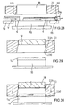
- Figure 38 shows that the lateral containing means may be formed by belts 100 rolled up on the belt conveyor means 3.
- the belts 100 are rolled up on rolling means 101 different from the roll 12 whereon the belt conveyor means is rolled up, with the transversal containing means 52a.
- the belts 100 are rolled up on rolling means 101 different from the roll 12 whereon the belt conveyor means is rolled up, with the transversal containing means 52a.
- the belts 100 are pressed on the rolling means 101 by anti-sliding means 102.
- the belts 100 are so detained between the pressing means 38a which keep them on the belt conveyor means 3 and the rolling means 101 whereon they are kept by the anti-sliding means 102.
- the peripheral speed of the rolling means 101 may be greater than the peripheral speed of the roll 12 so as to determine an elongation on the belts 100 with reduction of transverse section.
- Figure 39 shows that the belts 100, when they are kept between the rolls 12 and 13 with interposition of the belt conveyor means 3, have a section S3 lowered toward the belt conveyor means 3 and widening towards the powders during pressing. Therefore, at the end of the action of the rolls 12 and 13, the section S3 would tend, anyway, to go far away from the pressed powders and have the initial section S2 supporting the delivery of the pressed product 14.
Landscapes
- Engineering & Computer Science (AREA)
- Ceramic Engineering (AREA)
- Mechanical Engineering (AREA)
- Chemical & Material Sciences (AREA)
- Manufacturing & Machinery (AREA)
- Structural Engineering (AREA)
- Press-Shaping Or Shaping Using Conveyers (AREA)
- Devices For Post-Treatments, Processing, Supply, Discharge, And Other Processes (AREA)
Abstract
Description
- The present invention concerns a system for manufacturing powder material, in particular for the production of ceramic tiles.
- PCT/EP95/04560 describes a system for pressing ceramic tiles, wherein a continuous strip of powders having a predetermined thickness and width is formed, predetermined areas of said strip being compacted to obtain tiles, or pre-compacted semimanufactured products which are precursors of the tiles to be formed. In the latter case there is provided pressing of semimanufactured products in a die to obtain corresponding tiles ready to be subsequently dried and fired.
- US-A-3,540,093 describes an apparatus for manufacturing ceramic tiles, having substantially uniform compactness, homogeneity, density and thickness, wherein from a bottom end of a hopper, in which powders of ceramic material are contained, a vertical strip of compacted powders is formed by action of opposed pressing rolls, from said strip some pre-compacted products being subsequently severed by cutting and distributed on a horizontal conveyor from which the severed products are transferred to a die to obtain tile bodies.
- GB-A-880,892 describes an apparatus for forming clay material in which a mass of clay, humidified in such a way as to result at a plastic state, is laminated between a pair of rolls to obtain a layer of plastic material and subsequently the layer is formed by a forming die, without substantial alteration of the volume, in such a way as to obtain a plurality of tiles interconnected by webs which are subsequently cut by rotating disks.
- Prior art comprises also some apparatuses for making tiles in which powders are distributed in two superimposed layers during distinct strokes of a distributing trolley or distinct phases of the same stroke of a distributing trolley, the trolley being generally provided with grids and each one leading the powders of a determined layer at the matrix of the press. An example of such a kind of apparatuses is described in IT-A-1,069,458.
- Moreover, in such apparatuses there is a productivity much greater than the productivity obtainable loading in just one layer, since providing distinct strokes for each trolley, or distinct phases of the stroke of loading, is time consuming, since the various layers are loaded into a matrix of a respective die in different steps and in a certain interval of time.
- An object of the present invention is to improve the existent apparatuses for working ceramic tiles.
- In a first aspect of the present invention, there is provided a method for pressing powdered material to obtain tiles, comprising the steps of:
- distributing powders on flexible conveyor means and advancing said powders along an advancing direction through a pressing station,
- containing laterally said powders on said conveyor means by side containing means in said pressing station, said containing means being distinct from said powdered material,
- pressing said powders while advancing through said pressing station, characterized in that said containing means act on the powders to be pressed during said advancing and continue to act during said pressing.
- In a second aspect of the present invention, there is provided apparatus for pressing powdered material in such a way as to obtain tiles, comprising flexible conveyor means for receiving powders thereon from distributing means and for advancing said powders along an advancing direction through a pressing station, containing means for laterally containing said powders on said conveyor means, said containing means being distinct from said powdered material, means for pressing said powders while advancing through said pressing station, characterized in that said side containing means are arranged to act on the powders to be pressed during said advancing and said pressing of the powders.
- In a third aspect of the present invention, there is provided forming means for forming ceramic material comprising moving means arranged to move, along a reciprocal approaching direction, powders to be pressed and pressing means to decrease significantly the volume of said powders, the pressing means being arranged to press said powders along a pressing direction transversally disposed with respect to said approaching direction, characterized in that said pressing means are conformed to act on said powders with pressing intensity which increases along said approaching direction.
- In an advantageous embodiment, said pressing means comprises continuous pressing means, as rotating bodies, arranged to progressively press powders while said material advances.
- In a further embodiment, the pressing means comprises swinging pressing means disposed along the approaching direction.
- Owing to providing continuous pressing means combined with horizontally-disposed moving means for moving powders, it is possible to obtain an optimal compacting of ceramic material without alteration of the stratigraphic distribution of the powders and with limited loads.
- This allows to make ceramic tiles having valuable aesthetic effects in the surface even when an inexpensive ceramic support is used, because the aesthetic effects may occupy a thin surface layer of the ceramic tile.
- Moreover, using continuous pressing means acting on a horizontal strip of powders allows to significantly reduce the width of the areas of the strip of powders to be pressed and furthermore to limit scrap material.
- The forming of a continuous strip of pressed material renders possible feeding of the mould without using particular conveyor means: in fact the pressed strip may be advanced toward the mould by the action of pressing means acting on the belt conveyor means.
- To this end, the continuous pressing means may comprise rolls, belt conveyor means, swinging orbital elements and others.
- The invention will be better understood and carried into effect referring to the attached drawings, wherein:
- Figures 1, 2, 3, 4, are schematic side views, partially sectioned and interrupted, of an apparatus for forming ceramic tiles, respectively showing in sequence the phases of pre-compacting of powdered material and loading of the press, pressing and delivery of the pressed tiles;
- Figures 5, 6, 7, 8 are views corresponding to Figures 1, 2, 3, 4, but in a version of the forming apparatus;
- Figure 9 is a schematic side view, partially sectioned and interrupted, of continuous means for forming powders comprising a plurality of pairs of rollers opposite to the strip of powders;
- Figure 10 is a top view of Figure 9, showing the obtaining of two parallel strips of compacted powders on the same belt conveyor means;
- Figure 11 is the transversal section XI-XI of Figure 10;
- Figure 12 is a section as in Figure 9, but in which on the rolls which are above the strips of powders, compacting belt means are rolled up;
- Figure 13 is a view as in Figure 7, but in an embodiment wherein the front part of the strip of powders is rotated downwardly;
- Figure 14 is an interrupted, schematic longitudinal section of a version of continuous forming means obtained with pressing elements orbitally movable and co-operating with a longitudinally movable controlling element;
- Figures 15 and 16 are enlarged sections of a detail of pressing mould in the severing area of the compacted material, respectively in the phase of pressing and at the begin of the phase of extracting the pressed tile;
- Figure 17 is a view as in Figure 13, but during the loading phase of the mould;
- Figure 18 is a plan view taken along the plane XVIII-XVIII of Figure 17, wherein the compacted layer has dimension greater than the mould cavities;
- Figure 19 is a schematic side view of a version of forming apparatus showing severing means of the strip of compacted powders;
- Figure 20 is the schematic, top view of a layer of powders distributed on a belt conveyor means and pressed by continuous pressing rolls;
- Figure 21 is the section XXI-XXI of Figure 20;
- Figure 22 is a section as in Figure 21, but with continuous pressing means having an endless belt structure;
- Figures 23 is a schematic side view as in Figure 22, but in further embodiments;
- Figure 24 is a section as in Figure 14, but in an embodiment with belt conveyor means provided with cavities or hollows arranged to receive powders to be pressed;
- Figure 25 is a schematic, interrupted, vertical section of pressing means for pressing a pre-compacted ceramic product;
- Figure 26 is a section as in Figure 25, but in an intermediate phase of pressing and finishing of the edge of a product during pressing;
- Figure 27 is a section as in Figure 25, but in a final phase of pressing;
- Figure 28 is a section as in Figure 25, but in a phase of extracting the pressed tile;
- Figure 29 is a schematic, interrupted, vertical section of a further embodiment of pressing means for pressing a pre-compacted ceramic product;
- Figure 30 is a section as in Figure 29, but in an intermediate phase of pressing;
- Figure 31 is a front view, partially sectioned, of belt means with powders distributed thereon, roll pressing means and side containing means for lateral containing of said powders;
- Figure 32 is a schematic and interrupted top view of Figure 31;
- Figure 33 is a top view as in Figure 31, but without pressing means and in an embodiment with lateral containing means formed by swinging rigid side-walls;
- Figure 34 is a view as in Figure 32, but with containing means mainly obtained with exceed of powders;
- Figure 35 is the schematic section XXXV-XXXV of Figure 34;
- Figure 36 is a detail, enlarged and interrupted, of pressing means for pressing powders on belt conveyor means in a further embodiment;
- Figure 37 is a schematic, interrupted, side section of hopper distributing means arranged to distribute powders on belt conveyor means;
- Figure 38 is an enlarged and interrupted detail of a portion of end of the belt conveyor means for conveying powders provided with a tension device of the lateral containing means;
- Figure 39 is the section XXXIX-XXXIX of Figure 38.
- In the context of the following description, with the reference V is indicated the longitudinal direction of advance of loose or compacted powders on belt conveyor means. With the term "powders", each movable material at the solid state, including granular materials, ceramic glazes and clay compounds is indicated.
- As shown in Figures 1 to 4,
powders 1 are contained in hopper distributing means 2 having an outlet section controlled by adosing squegee 2a, which is adjustable in height and faces with a horizontal upper part of belt conveyor means 3, advancing the powders to be pressed at a press with mould means 4 for ceramic tiles 5 (Figure 4), in such a way as to form astrip 6, or main layer, of powders. Between thehopper 2 and the mould means 4, distributing decorating means 7 may be interposed to pour on thestrip 6 adecorating layer 8, the decorating means possibly comprising further hopper means 9 containing a decoratinggranular material 10, having the outlet section facing thestrip 6 and controlled by a rotatingdosing roll 11. - The belt conveyor means 3 is partially rolled up on a
roll 12 which defines an end of the belt conveyor means near to themould 4, rotating about a first, substantially horizontal axis A, defining a vertical plane whereon, above thestrip 6, a second axis B lies around which a secondpressing roll 13 forpressing powders powders rolls rolls strip layer 14, which is coherent, i.e. non-loose, and able to advance along a transferringplane 15 towards the mould means 4 under the action of a force exerted by therolls transferring plane 15, and defining a lower cavity 17 (Figure 2) arranged to contain longitudinally consecutive portions oflayer 14 of compacted powders and to allow their pressing between apunch 18 and abottom portion 19 of the mould means 4. Advancing of the compactedlayer 14 is controlled by the motion of therolls 12 and 13: thus, at the end of the pressing cycle, thelayer 14 is advanced by the said rolls until the elimination, from the pressing area, ofscrap materials 20 which may be collected by acrusher 21 and introduced again into the process as powders. The diameter of therolls - Referring to Figures 1 to 8, a pressing cycle comprises the following phases:
- 1) advancing the compacted
layer 14 by driving therolls - 2) approaching the
punch 18 to theportion 22 of the compactedlayer 14 which is above thelower cavity 17 and descending thepunch 18 and thebottom portion 19, underneath the movingplane 15, defined by lower frame means 16 to sever said portion from the compactedlayer 14 and insert it into the lower cavity 17 (Figure 2); - 3) pressing of the
portion 22 by descending of the punch towards the bottom portion 19 (Figures 3 and 7); - 4) lifting the
punch 18 and thebottom portion 19 in such a way as to be able to exit thetile 5 by exerting thereon a force by the compactedlayer 14 which is arriving. -
- It is observed that in the embodiments of the Figures 1 to 4 the lower frame means 16 are not vertically movable.
- In particular, referring to Figures 5 to 8, wherein the mould means are further provided with upper frame means 23 extending around the
punch 18, the pressing cycle comprises the phases 1) and 3) as defined above, and thephases 2a) and 4a) described below: - 2a) approaching the
punch 18 and the upper frame means 23 to theportion 22 of the compactedlayer 14 which is above thelower cavity 17 and descending the upper frame means 23 and the lower frame means 16 underneath the upper plane of thebottom portion 19 to sever saidportion 22 from the compactedlayer 14 and insert it into theupper cavity 23a of the upper frame means 23, saidupper cavity 23a having the same shape and dimensions as thelower cavity 17 of the lower frame means 16 (Figure 6); - 4a) lifting the
punch 18, the upper frame means 23 and the lower frame means 16 in such a way as to be able to exit thetile 5 exerting thereon a force by the compactedlayer 14 which is arriving, or, as shown in Figure 8, by means of suitable extractingmeans 24, provided, for example, withsuckers 25 and with rotating cleaningbrush 26 for thepunch 18. -
- In the
phase 2a), the lowering of the lower frame means 16 takes place together with the lowering of the movingplane 15, and, preferably, the belt conveyor means 3 withrespective rolls - In the phases 2) and 3), as well as in the
phases 2a) and 3), therolls - Figures 15 and 16 show the use of a mould such as that shown in Figures 5 to 8 to obtain a
tile 5 having a spacingportion 25 of greater dimension and afront face 26 formed above. - As shown in Figure 15, in the pressing a transversal expansion of the
tile 5 takes place to occupy the peripheral game G between the edge of the upper surface of thelower portion 19 of the mould and the internal surface of thecavity 23a. Moreover, during lifting of the frame means 16 and 23 after pressing, shown by the upwardly oriented arrow in Figure 16, an interference occurs between the edge of the pressedtile 5 and the corresponding edge of the compactedlayer 14 with removal of powders 27 of the same layer. To prevent the powders 27 from obstructing the movement between the lower frame means 16 and thebottom portion 19, between said means and said bottom portion a hollowannular area 28 is peripherally defined, as shown in Figures 15 and 16. - Figure 9 shows that, in addition to the
rolls upper rolls 29 and lower rolls, parallel to each other and torolls upper rolls 29 and the corresponding furtherlower rolls 30 being progressively increasing moving away from therolls powders 6. In this way, the angle C of incidence is conveniently small for each upper rolls 29, so as to decrease the risk of heterogeneities in compactation which would arise from longitudinal movings of the powders. - Figure 12 shows that on the plurality of upper
pressing rolls - The compacting belt means 31 allow to define carefully a predetermined value of the angle of incidence C and allow to exert on the
powders 6, 8 a particularly gradual action. - Figures 13 and 18 show that the end area of the belt. conveyor means 3 and the transferring
plane 15 next thereto may be hinged by a transversal axis Z passing through the strip ofpowders 6, before the area of beginning of compacting, in such a way as to allow the compactedmaterial 14 to follow the lowering and the lifting of the transferringplane 15 and of the lower frame means 16 in the phases of the pressing cycle described referring to Figures 5 to 8. To allow maintenance of the continuity of compacting, also the upper compacting belt means 31 must be free to rotate about the axis Z of a relatively wide angular sector. - Figure 18 shows that the lower frame means 16a may be open towards the moving
plane 15, in such a way as to surround the bottom 19 only in three side, so as to limit the discharged material. In fact, in the pressing cycle, the areas of the layer of compactedmaterial 14, which are subjected to the action of the upper frame means 23, cause an interruption of the continuity of such a layer; when the movingplane 15, rotating about the axis Z, goes down with respect to the bottom 19, its edge nearest to the bottom 19 is no longer complanate thereto and thus only theportion 35 of the layer of compactedmaterial 14, which are not subjected to the action of the frame means 23 and of thepunch 18, are severed from thelayer 14 along a fracture line Y. - As shown in Figures 10 and 11, the belt conveyor means 3 may be provided with projections acting as longitudinal severing means 36 for severing
powders 6, said severing means being received into respective recess means 38 of thepressing rolls parallel layers 14a of compacted material from tworespective layers 6a of powdered material. - The recess means 38 may define
pressing means 38a arranged to keep pressed, and, as a consequence, larger than their initial dimensions, the longitudinal severing means 36 and the lateral containing means 37 during pressing. This decreases the possibility of undesired moving of the severing means during pressing. Moreover, this supports the delivery of the pressedproducts 14 because, when the action of thepressing means 38a finishes, the longitudinal severing means 36 and the lateral containing means 37 assume again their initial dimensions, so detaching from the pressed products. - Near to the compacting area, there are provided, acting on the lateral containing means 37, lateral control means 39 limiting the deformations of the lateral containing means 37 during pressing, the lateral control means 39 advantageously comprising some rolls having vertical axes interacting with the lateral containing means 37 to avoid said lateral containing means 37 deforming outwardly during pressing.
- Preferably, the lateral containing means 37 define side walls having wide-apart shape toward the outside of the belt conveyor means 3 in such a way as to support the delivering of the
layer - The severing means 36 and the lateral containing means 37 may be made in elastic material in such a way as to be able to lengthen in the rolling on the rolls of the end of the belt conveyor means 3. Preferably the containing means are made in elastomeric material. This further supports the delivering of the compacted
material 14 from the side of themould 4. - If it is necessary to avoid, for further increasing the homogeneity of the pressing and the speed of the forming cycle, the layer of
powders 14 remaining still under the action of thepressing rolls punch 18 needs for forming tiles into themould 4, the entire group defined by the front end of the belt conveyor means 3 comprising theroll 12 and thepressing rolls mould 4 in such a way as to maintain uniform the relative speed of thepowders 6 with respect to such rolls. At the end of pressing, said group will be moved again near to themould 4. - The same could be made with the distributors of decorating
substances 7 and with thehopper 2. - Figure 14 shows that, to obtain the compactation of the
layer powders 6 and advance together with them along a portion of route of the belt conveyor means 3. Underneath the belt conveyor means 3 there is amovable controlling block 41, whereon the belt conveyor means 3 rests, the block being free to move along the direction Y1 toward the mould means 4 when the compacting means 40 compresses thepowders 6 and to return at the initial position, under the action of areturn spring 42, when the compacting means 40 does not compress thepowders 6. For this purpose, themovable block 41 is set up onrolls 43 interposed between theblock 41 and abase body 44. - The compacting action of the compacting means 40 may also be obtained by a suitable vibrating-generator device: therefore the action of the compacting means 40 on the
powders 6 may take place in a vertical plane orthogonal to the belt conveyor means 3. - In an embodiment not shown, between the
rolls layer 14 of compacted powders. - Moreover, the surface of the
roll 13 may be suitably hollow, or in relief, to obtain reliefs or, respectively depressions, in the upper face of thestrip strip 14 suitable to receive further decorating substances. - In the embodiment with mould means 4 shown so far, the contact between the upper frame means 23 and the lower frame means 16 in the respective stroke downward to isolate the
areas 22 is to be prevented in such a way as to maintain thelayer 4 integral: for the purpose, as shown in Figure 17, between said upper and lower frame means there are advantageously spacing means 45, comprising for example mechanical controlling means, or electronic control means, such as to maintain a predetermined distance between the upper and lower frame means: in this way the action of first vertical driving means 46 for driving the upper frame means 23 and of second vertical driving means 47 for driving the lower frame means 16 is controlled. The first vertical driving means 46 are connected with acrossbar 48 of the press, while the second vertical driving means 47 are connected with thebase 49. - Referring to Figure 19, between the continuous pressing means 12, 13 and the mould means 4, severing means 50 may be inserted to sever, from the
layer 14, pre-formed elements to insert into themould 4 by suitable forcing means, eventually incorporated into the severing means, which may be provided, in addition to a motion in the plane which is transverse with respect to thelayer 14, as shown by the arrow F2, also with a motion in a longitudinal direction shown by the arrow F3 and parallel to the direction V of advancing of thepowders pressing rolls - Advantageously, the severing means 50 may be constituted by rotating disks or by a pair of cutters lying in opposite side with respect to the compacted
layer 14 to cause its cut or fracture along a predetermined fracture line. - Figure 20 and 21 show an embodiment of apparatus for pressing powders on belt conveyor means 3 wherein the
powders 54 are pressed by a pair ofrolls upper roll 29 and by alower roll 30. - As shown, in particular, in Figure 21, the transversal containing means may be formed by
transversal lips 52a projecting from the belt conveyor means 3 and having narrowing section going far from the belt conveyor means. In particular, thepowders 54 may be distributed in a layer having initial thickness greater than the height of thelips 52a and the height of thelips 52a may such that, after pressing, the powders of acavity 53 may result severed from the powders of thenext cavities 53 by means of thelips 52a. - Figure 22 shows a further embodiment of the apparatus for pressing powders wherein a
non-pressed layer 6 distributed on belt conveyor means 3 is pressed by belt pressing means 58 comprising upper belt means 59 ring-rolled up on theroll 13 and on an auxiliary roll 60: between therolls block 61, whereon somerolls 62 are rolling-coupled, said rolls 62 being operatively interposed between an active part of the belt means 59 facing the powders, which have being pressed, and the controllingblock 61. Below the belt conveyor means 3 for supporting thepowders 6 there is advantageously provided an analogouscontrolling block 61a with respective rolling rolls 62a which are operatively interposed between theblock 61a and the belt conveyor means 3. - The arrangement is such that the belt means 59 is tilted in the direction of advancing of the powders in such a way that between the belt conveyor means 3 and the upper belt means 59 a thickness of powders, which progressively decreases in the V-direction of advancing of the powders, is defined.
- Figure 23 shows that, to feed a
press 4 withpre-compacted elements 14, a roll means 15a may be used and that thepowders rolls adjustable block 61 and the respective rolling. rolls 62. It is also shown that the tile obtainable from pressedpowders 14 may be formed with the decorated face facing downwards, if thedecorating substances 8 are distributed on the belt conveyor means 3 before the thicker portion ofpowders 6 forming the support is distributed thereon. - Figures 20 to 23 show versions wherein powders to be pressed interact with pressing means on belt conveyor means in a particularly gradual way and therefore the risk of therir being pushed back on the belt conveyor means 3 thereby is greatly reduced.
- Figure 24 shows that the space defined between the compacting
layer 40 and the belt conveyor means 3 has a first portion R with decreasing height to decrease the thickness of thepowders - The use of the portions R, R1 in sequence, having respectively decreasing and constant height in the direction shown by arrow V, is obtainable in the embodiments of Figures 9, 10, 11, 12, 13, 14, 17, 20, 21, 22, 23 with a suitable arrangement of the pressing means.
- Moreover, there is provided a compacting
belt 59a interposed between thepowders 6 to be pressed and the compacting means 40, advantageously provided with transversal severing means 52b extending toward the belt conveyor means 3 to sever, from the top, the layer ofpowders 6 during pressing. - The compacting means 40 may be elastically coupled with supporting means through elastic harmonizing means 40a and may be also coupled with vibration generating means 40b.
- With reference to Figures 14 and 24, it is observed that the compacting means 40 may also be provided only with a reciprocating motion in a direction orthogonal to the belt conveyor means 3 and, in this case, the belt conveyor means 3 has to be driven with intermittent motion, i.e. step by step.
- Figures 25 to 28 show that the
press 4 may have, close to the internal edge of the upper frame means 23, an annular edge-zone 23b being part of thecavity 23a and made in such a way as to correspondly form an external edge of thetile 5; advantageously, the annular edge-zone 23b is provided with a cuttingcorner 23c to remove an exceeding portion of thepre-compacted product 14 when the upper frame means 23 descend toward theproduct 14 to be pressed. - Positioning means 63 bring the
product 14 under thepunch 18 in a central position with respect to the hollow defined by upper frame means 23 and extractingmeans 64 extract the formedtile 5 from the pressing area. - The extracting means 64 may be provided with a depressurizing
element 65 extending along an edge of thetile 5 and provided with anopening 66 through which, for difference in pressure, the correspoding edge of the tile is caught with a force sufficient to keep caught the tile while it is moved. - As shown in Figures 29 and 30, the upper frame means 23 may be provided with a diverging
area 23d which spreads toward theproduct 14 to be pressed in such a way as to fix it in the centre thereof when the frame means 23 are descended for the pressure. - In this embodiment it is not necessary to position the
products 5 accurately under thepunch 18. - In the embodiments shown in Figures 31 to 34, the lateral containing means for containing powders are boundless to the belt conveyor means 3 and act directly on the
powders longitudinal severing partitions 36. The lateral containing means may comprise belt conveyor means 67 formed by a pair of belt means 68 rolled up onrespective pulleys 69 supported to rotation about axes substantially orthogonal to the belt conveyor means 3 near to thepressing rolls - Figure 31 and 32 show embodiments wherein the belt conveyor means 3 has not transversal severing means and, thus, from the
powders 6, 8 a continuouspressed product 14 is obtained. - In the embodiment of Figure 33, the belt conveyor means 3 is provided with transversal severing means 52 and the lateral containing means for containing
powders 54 are formed byrigid side walls 70 which extend laterally to the cavity in which the said powders are contained and may swing between the position indicated with continuous line and the position with dashed line to unengaged from thepowders 54 after pressing has taken place with one of the systems described so far. - In Figures 34, 35 the lateral containing means are formed by exceeding
portions 71 ofpowders rolls - Figure 36 shows an embodiment of pressing means for pressing powders wherein the
powders plates 76, severed in two groups of plates hinged to form rings, acts on the belt means 3, 59a from the side opposite to the one in contact with the powders, said rings being anupper ring 77 of plates acting on the upper belt means 59a and alower ring 78 of plates acting on the lower belt conveyor means 3. Upper rolls 79 andlower rolls 80, defining planes of advancing of theplates 76, act on the rings ofplates - It is observed that the belt means 3, 59a may be omitted and, in this case, the
powders plates 76 disposed below thepowders - The
rolls blocks - It is observed that the belt conveyor means 3 is provided with
transverse lips 52b extending, inside thepowders lips 52b remain inserted inside the thickness of thepowders lips 52b define some predetermined fracture planes Z for the pressed powders. - Figure 37 shows that in an apparatus for pressing ceramic tiles there are provided
hopper distributing means 81 which pour various types ofpowders single outlet 81a, in such a way as to form on said belt conveyor means a formation of powders defining grains simulating the effect of natural stones. - To obtain the greatest variety of decorating effects, the types of
powders hopper 81 by respective conduit means 83, 84, 85 which are coupled with respective driving means inside thehopper distributing means 81, in such a way as to allow to vary the allocation of the powders inside the hopper distributing means and consequently vary the structure of the layer ofpowders - Figure 38 shows that the lateral containing means may be formed by
belts 100 rolled up on the belt conveyor means 3. - Advantageously, the
belts 100 are rolled up on rolling means 101 different from theroll 12 whereon the belt conveyor means is rolled up, with thetransversal containing means 52a. In this way it is possible to lengthen thebelts 100 in the portion comprised between the detaching zone from the belt conveyor means 3 and the respective rolling means 101 in such a way as to decrease the section S1 with respect to the section S2 which the belts have in the remaining portions. - Preferably, the
belts 100 are pressed on the rolling means 101 byanti-sliding means 102. Thebelts 100 are so detained between thepressing means 38a which keep them on the belt conveyor means 3 and the rolling means 101 whereon they are kept by the anti-sliding means 102. In this way, the peripheral speed of the rolling means 101 may be greater than the peripheral speed of theroll 12 so as to determine an elongation on thebelts 100 with reduction of transverse section. - This allows to support the extraction of the pressed
product 14 form the cavities obtained on the belt conveyor means 3. - Figure 39 shows that the
belts 100, when they are kept between therolls rolls product 14.
Claims (26)
- Method for pressing powdered material to obtain tiles, comprising the steps of:distributing powders on flexible conveyor means and advancing said powders along an advancing direction through a pressing station,containing laterally said powders on said conveyor means in said pressing station by side containing means distinct from said powdered material,pressing said powders while advancing through said pressing station, characterized in that said containing means act on the powders to be pressed during said advancing and continue to act during said pressing.
- Method according to claim 1, wherein said containing means are movable along a plane substantially parallel to said conveyor means.
- Method according to anyone of the preceding claims and further comprising, after said pressing, severing portions from said pressed powders in such a way as to obtain, from said portions, corresponding tiles.
- Method according to anyone of the preceding claims, wherein said distributing comprises distributing said powders in different zones of said conveyor means.
- Method according to anyone of the preceding claims and further comprising further pressing said powders after said pressing.
- Method according to claim 1, wherein said pressing comprises acting on said powders with pressing intensity which increases along said advancing direction.
- Apparatus for pressing powdered material in such a way as to obtain tiles, comprising flexible conveyor means for receiving powders thereon from distributing means and for advancing said powders along an advancing direction through a pressing station, containing means for laterally containing said powders on said conveyor means, said containing means being distinct from said powdered material, means for pressing said powders while advancing through said pressing station, characterized in that said side containing means are arranged to act on the powders to be pressed during said advancing and said pressing of the powders.
- Apparatus according to claim 7, characterized in that said conveyor means are selected in a group comprising belt conveyor means, articulated-plate conveyor means.
- Apparatus according to claim 7, or 8, wherein said containing means comprise at least a pair of containing elements co-operating with said conveyor means.
- Apparatus according to anyone of the claims 7 to 9, wherein said containing elements comprise at least a pair of wall means obtained in said conveyor means.
- Apparatus according to anyone of the claims 7 to 10, wherein said containing means comprise a pair of rolling means acting on edge zones of said conveyor means.
- Apparatus according to anyone of the claims 7 to 11, and further comprising severing means to sever from the pressed powders portions defining tiles.
- Apparatus according to anyone of the claims 7 to 12, wherein said pressing means comprise roll pressing means which define a passing section for said material which decreases along an advancing direction (V) of the material.
- Apparatus according to claim 13, wherein on a portion of said roll pressing means compacting belt means (31, 59) are rolled up.
- Apparatus according to claim 14, wherein said compacting belt means co-operate with controlling means and with rolling means interposed between said compacting belt means (31, 59) and said controlling means.
- Apparatus according to anyone of the claims 7 to 13, wherein said pressing means comprise at least a compacting means (40) provided with swinging motion.
- Apparatus according to anyone of the claims 7 to 16 wherein said pressing means comprises at least a compacting means (40)provided of a first pressing surface portion forming an angle with said conveyor means and a second pressing surface portion substantially parallel to said conveyor means.
- Apparatus according to anyone of the claims 7 to 17, wherein said conveyor means is indexable along a rectilinear path in a direction orthogonal to a direction along which said pressing means (40) are movable.
- Apparatus according to anyone of the claims 7 to 17, wherein said pressing means (40) is movable along more than one rectilinear directions.
- Apparatus according to anyone of the claims 16 to 19, wherein on a portion of said pressing means (40) compacting belt means (59a) are cooperating.
- Apparatus according to anyone of the claims 14 to 20, wherein said compacting belt means (31, 59, 59a) are provided with severing means (52b) oriented towards said powder material (6, 8).
- Apparatus according to claim 21, wherein said severing means (52b) are defined by oblique walls inclined with respect of said compacting belt means (31, 59, 59a).
- Apparatus according to anyone of the claims 7 to 22, wherein, downstream of said pressing means (12, 13; 12, 30, 13, 29; 12, 30, 13, 29, 31; 40, 41) there are provided further pressing means (4) for further compacting said material.
- Apparatus according to anyone of the claims 7 to 23 wherein said distributing means comprise hopper distributing means.
- Apparatus according to anyone of the claims 7 to 24, wherein said distributing means comprise belt distributing means.
- Forming means for forming ceramic material comprising moving means arranged to move, along a reciprocal approaching direction, powders to be pressed and pressing means to decrease significantly the volume of said powders, the pressing means being arranged to press said powders along a pressing direction transversally disposed with respect to said approaching direction, characterized in that said pressing means are conformed to act on said powders with pressing intensity which increases along said approaching direction.
Applications Claiming Priority (7)
| Application Number | Priority Date | Filing Date | Title |
|---|---|---|---|
| ITMO960151 | 1996-11-22 | ||
| IT96MO000151 IT1287505B1 (en) | 1996-11-22 | 1996-11-22 | Continuous pressing method and plant for production of tiles - involves controlled discharge of contained layer of powder on conveyor belt that advances through pre-pressing rollers to mould and pressing punch |
| ITMO970004 | 1997-01-16 | ||
| ITMO970005 | 1997-01-16 | ||
| IT97MO000004 IT1292653B1 (en) | 1997-01-16 | 1997-01-16 | Continuous pressing method and plant for production of tiles - involves controlled discharge of contained layer of powder on conveyor belt that advances through pre-pressing rollers to mould and pressing punch |
| IT97MO000005 IT1292654B1 (en) | 1997-01-16 | 1997-01-16 | Continuous pressing method and plant for production of tiles - involves controlled discharge of contained layer of powder on conveyor belt that advances through pre-pressing rollers to mould and pressing punch |
| EP97945854A EP0939691A2 (en) | 1996-11-22 | 1997-10-17 | Manufacturing of powdered material |
Related Parent Applications (1)
| Application Number | Title | Priority Date | Filing Date |
|---|---|---|---|
| EP97945854A Division EP0939691A2 (en) | 1996-11-22 | 1997-10-17 | Manufacturing of powdered material |
Publications (3)
| Publication Number | Publication Date |
|---|---|
| EP1283097A2 true EP1283097A2 (en) | 2003-02-12 |
| EP1283097A3 EP1283097A3 (en) | 2003-03-19 |
| EP1283097B1 EP1283097B1 (en) | 2006-08-09 |
Family
ID=27274124
Family Applications (5)
| Application Number | Title | Priority Date | Filing Date |
|---|---|---|---|
| EP02023590A Expired - Lifetime EP1283097B1 (en) | 1996-11-22 | 1997-10-17 | Method for pressing powdered material |
| EP01119708A Expired - Lifetime EP1175982B1 (en) | 1996-11-22 | 1997-10-17 | Method for pressing powder material |
| EP97945854A Withdrawn EP0939691A2 (en) | 1996-11-22 | 1997-10-17 | Manufacturing of powdered material |
| EP01119710A Expired - Lifetime EP1170105B1 (en) | 1996-11-22 | 1997-10-17 | Manufacturing of powdered material |
| EP01119709A Expired - Lifetime EP1170104B1 (en) | 1996-11-22 | 1997-10-17 | Distributing means for distributing powder material |
Family Applications After (4)
| Application Number | Title | Priority Date | Filing Date |
|---|---|---|---|
| EP01119708A Expired - Lifetime EP1175982B1 (en) | 1996-11-22 | 1997-10-17 | Method for pressing powder material |
| EP97945854A Withdrawn EP0939691A2 (en) | 1996-11-22 | 1997-10-17 | Manufacturing of powdered material |
| EP01119710A Expired - Lifetime EP1170105B1 (en) | 1996-11-22 | 1997-10-17 | Manufacturing of powdered material |
| EP01119709A Expired - Lifetime EP1170104B1 (en) | 1996-11-22 | 1997-10-17 | Distributing means for distributing powder material |
Country Status (7)
| Country | Link |
|---|---|
| EP (5) | EP1283097B1 (en) |
| AU (1) | AU5120198A (en) |
| DE (4) | DE69738589T2 (en) |
| ES (4) | ES2266061T3 (en) |
| IT (1) | IT1287505B1 (en) |
| PT (2) | PT1283097E (en) |
| WO (1) | WO1998023424A2 (en) |
Cited By (6)
| Publication number | Priority date | Publication date | Assignee | Title |
|---|---|---|---|---|
| EP1500480A2 (en) * | 2003-07-22 | 2005-01-26 | System S.p.A. | A device for forming ceramic products, including slabs, tiles and the like, by powder pressing |
| WO2009010361A1 (en) | 2007-07-18 | 2009-01-22 | Sacmi Cooperativa Meccanici Imola Societa' Cooperativa | A ceramic material and slabs obtained with the ceramic material |
| ITPD20110104A1 (en) * | 2011-04-07 | 2012-10-08 | Cooperativa Ceramica D Imola S C | PROCEDURE FOR THE CONSTRUCTION OF CERAMIC SHEETS OF LARGE SIZE |
| WO2016046724A1 (en) | 2014-09-22 | 2016-03-31 | Sacmi Cooperativa Meccanici Imola Societa' Cooperativa | Line for the production of individual products in succession in a continuous cycle |
| CN110193968A (en) * | 2019-06-06 | 2019-09-03 | 唐竹胜 | Quantitative powder material distribution device and method |
| US20210114254A1 (en) * | 2018-03-26 | 2021-04-22 | System Ceramics S.P.A. | Method for pressing ceramic slabs |
Families Citing this family (58)
| Publication number | Priority date | Publication date | Assignee | Title |
|---|---|---|---|---|
| IT1292745B1 (en) * | 1997-06-10 | 1999-02-11 | Alberto Franceschini | PROCESS AND PLANT FOR THE FORMING OF CERAMIC AND SIMILAR TILES. |
| IT1303926B1 (en) * | 1998-03-02 | 2001-03-01 | Sergio Miotto | METHOD AND MEANS FOR FORMING CERAMIC TILES. |
| IT1306349B1 (en) * | 1998-08-21 | 2001-06-06 | Merli Fabio | MOLD CAVITY FEEDING DEVICE IN CERAMIC AND RELATED PRODUCT PRESSES |
| IT1302213B1 (en) * | 1998-09-16 | 2000-09-05 | Siti | DEVICE FOR FEEDING A PRESSING APPARATUS, PRESSING APPARATUS AND PRESSING PROCESS. |
| DE69918511T2 (en) * | 1998-09-28 | 2005-08-25 | Camorani, Carlo Antonio, Roteglia di Castellarano | Method and device for transferring granular material |
| EP0995562A1 (en) * | 1998-10-15 | 2000-04-26 | Ronflette S.A. | A device for forming ceramic products such as tiles and the like, by powder pressing |
| EP0995563A1 (en) * | 1998-10-15 | 2000-04-26 | Ronflette S.A. | A plant and process for forming ceramic products, such as tiles and the like, by powder pressing |
| EP1005967A1 (en) * | 1998-11-30 | 2000-06-07 | Ceramiche Provenza S.R.L. | Process and device for loading the moulds of pressure-glazed tile-forming presses |
| DE60007958T2 (en) * | 2000-03-23 | 2004-12-16 | System S.P.A., Fiorano | Improved device for manufacturing ceramic objects such as plates, tiles and similar articles by pressing powder |
| EP1136211B1 (en) * | 2000-03-23 | 2004-06-02 | SYSTEM S.p.A. | A device for forming ceramic products, including slabs, tiles and the like, by powder pressing |
| DE60000542T2 (en) | 2000-07-25 | 2003-06-26 | R P Srl | Method and device for filling molds for the production of ceramic tiles |
| IT1320102B1 (en) * | 2000-11-24 | 2003-11-18 | Marazzi Gruppo Ceramiche S P A | PRESS FOR THE PRODUCTION OF TILES, EQUIPPED WITH TAPE LOADING DEVICES. |
| ITRE20010047A1 (en) | 2001-05-08 | 2002-11-08 | Sacmi | PLANT FOR THE FORMING OF LARGE CERAMIC TILES, AND METHOD |
| ITRE20010067A1 (en) * | 2001-06-12 | 2002-12-12 | Sacmi | METHOD AND PLANT FOR THE FORMING OF LARGE SIZES AND CERAMIC TILES |
| ITMO20020026A1 (en) * | 2002-02-07 | 2003-08-07 | Ronflette Sa | METHOD AND EQUIPMENT FOR THE DECORATION OF CERAMIC SLABS OR TILES |
| ITRE20020035A1 (en) * | 2002-04-24 | 2003-10-24 | Sacmi | METHOD AND PLANT FOR THE FORMING OF SLABS OR CERAMIC TILES |
| ITMO20020175A1 (en) * | 2002-06-20 | 2003-12-22 | Ronflette Sa | DUST LOADING DEVICE |
| ITMO20020234A1 (en) * | 2002-08-12 | 2004-02-13 | Algeri Maris | DEVICE AND METHOD FOR TRANSFERRING GRANULAR MATERIAL. |
| ITBO20030032A1 (en) * | 2003-01-24 | 2004-07-25 | T S C Spa | APPARATUS FOR THE APPLICATION OF POWDER PRODUCTS |
| ITBO20030114A1 (en) * | 2003-03-04 | 2004-09-05 | T S C Spa | POWER SUPPLY DEVICE FOR THE APPLICATION OF PRODUCTS |
| AU2003902691A0 (en) * | 2003-05-30 | 2003-06-19 | E.I.F.S. Holdings Limited | Method of forming composite light weight panels |
| ITRE20030071A1 (en) * | 2003-07-07 | 2005-01-08 | Sacmi | METHOD AND PLANT FOR FORMING SHEETS OR |
| ITMO20030251A1 (en) * | 2003-09-17 | 2005-03-18 | Mira Di Algeri Maris | METHOD AND APPARATUS FOR DECORATING. |
| ITRE20040001A1 (en) * | 2004-01-08 | 2004-04-08 | Sacmi | METHOD AND PLANT FOR THE PREPARATION OF THE POWDERS FOR THE FORMING OF TILES OR CERAMIC SLABS |
| ITTV20040118A1 (en) * | 2004-10-20 | 2005-01-20 | Luca Toncelli | EQUIPMENT FOR THIN LAYER DISTRIBUTION OF A MIXTURE BASED ON STONE OR AGGLOMERATE CERAMIC MATERIAL. |
| ITRE20040151A1 (en) * | 2004-12-10 | 2005-03-10 | Sacmi | IMPROVED PLANT FOR FORMING CERAMIC SHEETS OR TILES |
| ITRE20040150A1 (en) * | 2004-12-10 | 2005-03-10 | Sacmi | IMPROVED PLANT FOR FORMING CERAMIC SHEETS OR TILES |
| ITRE20050086A1 (en) * | 2005-07-19 | 2007-01-20 | Sacmi | SYSTEM TO ALTER THE ARRANGEMENT OF DUSTY DUST A STRIP FOR THE FORMING OF TILES OR CERAMIC SHEETS |
| ES2658834T3 (en) | 2006-02-21 | 2018-03-12 | System Spa | Decoration with powder material |
| ITRE20070108A1 (en) * | 2007-10-15 | 2009-04-16 | Sacmi | '' SYSTEM FOR CONTINUOUS POWDER FEEDING IN THE MANUFACTURE OF CERAMIC TILES '' |
| WO2010006264A1 (en) * | 2008-07-10 | 2010-01-14 | Ness Inventions, Inc. | Concrete block machine having a controllable cutoff bar |
| WO2010128953A1 (en) | 2009-05-04 | 2010-11-11 | Scg Building Materials Co., Ltd. | Method and apparatus for forming and pressing powder materials |
| US20100310695A1 (en) | 2009-06-03 | 2010-12-09 | Keystone Retaining Wall Systems, Inc. | Floating cut-off bar and method of use thereof |
| US8568129B2 (en) | 2009-06-03 | 2013-10-29 | Keystone Retaining Wall Systems Llc | Floating cut-off bar for a mold box |
| US9808957B2 (en) * | 2010-01-26 | 2017-11-07 | Oldcastle Architectural, Inc. | Mould filling method |
| CN101786290B (en) * | 2010-02-11 | 2013-07-10 | 佛山市点石机械有限公司 | Material distributing method for forming emperador pattern on polished tile |
| IT1398239B1 (en) * | 2010-02-26 | 2013-02-22 | T S C S P A | DEVICE FOR COMPACTING A LAYER OF CERAMIC POWDERS AND DEVELOPABLE METHOD BY THE DEVICE |
| CN103635296B (en) * | 2011-04-22 | 2016-10-26 | 维克Ip控股公司 | The device of goods, system and method and the compression goods formed by it are compressed for being formed |
| CN102350728B (en) * | 2011-09-24 | 2013-05-08 | 湖南天牌实业有限公司 | Large fibrous plaster molding device |
| ITRE20110081A1 (en) * | 2011-10-07 | 2013-04-08 | Sacmi | DEVICE AND METHOD FOR THE TREATMENT OF A LAYER OF MATERIAL POWDER |
| ITMI20120614A1 (en) * | 2012-04-16 | 2013-10-17 | Gambarelli S R L | APPARATUS FOR FORMING CRUDE CERAMIC SHEETS OF LARGE SIZE |
| KR101552018B1 (en) * | 2012-11-07 | 2015-09-09 | 오씨아이 주식회사 | Apparatus for molding core of vacuum insulation panel and vacuum insulation panel manufactured thereby |
| ITMI20131708A1 (en) * | 2013-10-15 | 2015-04-16 | Tech S R L G | APPARATUS FOR FORMING CERAMIC SLABS |
| ITUA20164307A1 (en) * | 2016-06-13 | 2017-12-13 | Sacmi | MACHINE AND METHOD FOR THE COMPACTION OF CERAMIC POWDER |
| CN107398987B (en) * | 2017-09-29 | 2019-03-29 | 江西斯米克陶瓷有限公司 | A kind of apparatus for distributing and technique of imitative stone pattern reason vitrified tile |
| WO2019092628A1 (en) * | 2017-11-10 | 2019-05-16 | System S.P.A. | A device for pressing ceramic powders |
| WO2020049520A1 (en) * | 2018-09-07 | 2020-03-12 | Sacmi Cooperativa Meccanici Imola Societa' Cooperativa | Machine and method for compacting a powder material |
| IT201800010612A1 (en) * | 2018-11-27 | 2020-05-27 | Granitifiandre Spa | METHOD AND PLANT FOR THE FORMING OF CERAMIC SHEETS |
| CN112171863A (en) * | 2019-07-01 | 2021-01-05 | 徐州市贾汪区羡人工贸有限公司 | Compaction equipment of building fragment of brick production usefulness |
| CN111347547A (en) * | 2020-04-01 | 2020-06-30 | 太仓北新建材有限公司 | Extrusion device of gypsum slurry |
| WO2022118214A1 (en) * | 2020-12-01 | 2022-06-09 | Sacmi Cooperativa Meccanici Imola Societa' Cooperativa | Compacting machine and plant for manufacturing ceramic articles |
| CN112571848B (en) * | 2020-12-21 | 2022-06-21 | 广东鸿懿药业科技有限公司 | Preparation method of eye cosmetic |
| IT202100024588A1 (en) * | 2021-09-24 | 2023-03-24 | Cooperativa Ceramica Dimola Soc Cooperativa In Breve Cooperativa Ceramica Dimola S C | PROCEDURE AND PLANT FOR THE REALIZATION OF DECORATIVE ELEMENTS IN CERAMIC MATERIAL |
| CN113696321B (en) * | 2021-11-01 | 2022-01-28 | 佛山市高明贝斯特陶瓷有限公司 | Ceramic production system based on digital cloth |
| CN114055602B (en) * | 2021-11-10 | 2023-05-30 | 安庆惠嘉新型建材有限公司 | Auxiliary device for red brick die casting |
| ES2896309B2 (en) * | 2021-11-24 | 2024-03-06 | Kerajet S A | CERAMIC POWDER LAMINATING PRESS WITH INTERCHANGEABLE ROLLER AND ROLLER EXCHANGE METHOD OF A LAMINATING PRESS |
| SE2250089A1 (en) * | 2022-01-31 | 2023-08-01 | Reliefed Ab | A production method, and a ceramic product obtained by such method |
| WO2023233317A1 (en) * | 2022-05-31 | 2023-12-07 | Sacmi Cooperativa Meccanici Imola Societa' Cooperativa | Compacting machine and plant for producing ceramic products |
Citations (4)
| Publication number | Priority date | Publication date | Assignee | Title |
|---|---|---|---|---|
| US2195683A (en) * | 1937-01-28 | 1940-04-02 | Rostone Inc | Block and tile pressing machine |
| JPH0272904A (en) * | 1988-09-07 | 1990-03-13 | Nippon Kouatsu Electric Co | Molding method of wall material and the like |
| FR2640544A1 (en) * | 1988-12-21 | 1990-06-22 | Combe Daniel | PROCESS FOR PRODUCING CONTINUOUS PANELS AND MACHINE FOR IMPLEMENTING SAME |
| US5145627A (en) * | 1989-11-20 | 1992-09-08 | Efisol | Process for producing colored decorative panels based on exfoliated rock particles |
Family Cites Families (15)
| Publication number | Priority date | Publication date | Assignee | Title |
|---|---|---|---|---|
| US1377188A (en) * | 1919-12-27 | 1921-05-10 | Hans P Domine | Tile-forming machine |
| US2082721A (en) * | 1935-09-10 | 1937-06-01 | Sanford Charles Lemuel | Concrete block machine |
| DE1142265B (en) * | 1956-10-11 | 1963-01-10 | Jurid Werke Gmbh | Process for the production of pellets to be sintered from metal powder |
| FR1182282A (en) * | 1957-05-16 | 1959-06-24 | Titanium | Process for the agglomeration of divided materials |
| GB880892A (en) * | 1959-10-05 | 1961-10-25 | Alexander John Cherney | An improved method and apparatus for the manufacture of tiles |
| US3540093A (en) * | 1966-03-21 | 1970-11-17 | Interpace Corp | Apparatus for manufacture of pressed ceramic articles |
| DE2016954A1 (en) * | 1970-04-09 | 1971-10-21 | Laeis-Werke Ag, 5500 Trier | Method and device for the production of ceramic plates |
| US3901634A (en) * | 1972-11-09 | 1975-08-26 | John B Webb | Compactor for producing cement wall panels |
| EP0024237A3 (en) * | 1979-08-09 | 1981-07-15 | So.De.Em Societe D'exploitation Des Etablissements Minato | Moulding press for concrete products comprising a concrete feed system |
| NL8701601A (en) * | 1987-07-08 | 1989-02-01 | Mosa Koninkl Bv | FLOOR TILE SET, METHOD FOR PRODUCING A FLOOR TILE FOR THE SET AND APPARATUS FOR CARRYING OUT THE METHOD |
| JP2643378B2 (en) * | 1988-10-26 | 1997-08-20 | 松下電工株式会社 | Sanding equipment |
| JPH05253462A (en) * | 1992-02-26 | 1993-10-05 | C C A Kk | Device for supplying powder and granular material with fixed bed depth and production of patterned formed body using the same device |
| FR2714048B1 (en) * | 1993-12-16 | 1996-02-16 | Everite Sa | Article, in particular a building cladding plate, and method of manufacturing such an article. |
| US5419246B1 (en) * | 1994-08-02 | 1998-06-09 | Kenneth Bibby | Method and apparatus for laying a granular pattern |
| IT1269274B (en) * | 1994-11-22 | 1997-03-26 | Carlo Antonio Camorani | METHOD FOR FORMING CERAMIC TILES AND RELATED PLANT |
-
1996
- 1996-11-22 IT IT96MO000151 patent/IT1287505B1/en active IP Right Grant
-
1997
- 1997-10-17 PT PT02023590T patent/PT1283097E/en unknown
- 1997-10-17 PT PT01119710T patent/PT1170105E/en unknown
- 1997-10-17 DE DE69738589T patent/DE69738589T2/en not_active Expired - Lifetime
- 1997-10-17 ES ES01119709T patent/ES2266061T3/en not_active Expired - Lifetime
- 1997-10-17 EP EP02023590A patent/EP1283097B1/en not_active Expired - Lifetime
- 1997-10-17 ES ES02023590T patent/ES2269584T3/en not_active Expired - Lifetime
- 1997-10-17 ES ES01119710T patent/ES2311495T3/en not_active Expired - Lifetime
- 1997-10-17 WO PCT/EP1997/005742 patent/WO1998023424A2/en not_active Application Discontinuation
- 1997-10-17 DE DE69738916T patent/DE69738916D1/en not_active Expired - Lifetime
- 1997-10-17 AU AU51201/98A patent/AU5120198A/en not_active Abandoned
- 1997-10-17 EP EP01119708A patent/EP1175982B1/en not_active Expired - Lifetime
- 1997-10-17 EP EP97945854A patent/EP0939691A2/en not_active Withdrawn
- 1997-10-17 DE DE69736362T patent/DE69736362T2/en not_active Expired - Lifetime
- 1997-10-17 EP EP01119710A patent/EP1170105B1/en not_active Expired - Lifetime
- 1997-10-17 DE DE69736496T patent/DE69736496D1/en not_active Expired - Lifetime
- 1997-10-17 ES ES01119708T patent/ES2301507T3/en not_active Expired - Lifetime
- 1997-10-17 EP EP01119709A patent/EP1170104B1/en not_active Expired - Lifetime
Patent Citations (4)
| Publication number | Priority date | Publication date | Assignee | Title |
|---|---|---|---|---|
| US2195683A (en) * | 1937-01-28 | 1940-04-02 | Rostone Inc | Block and tile pressing machine |
| JPH0272904A (en) * | 1988-09-07 | 1990-03-13 | Nippon Kouatsu Electric Co | Molding method of wall material and the like |
| FR2640544A1 (en) * | 1988-12-21 | 1990-06-22 | Combe Daniel | PROCESS FOR PRODUCING CONTINUOUS PANELS AND MACHINE FOR IMPLEMENTING SAME |
| US5145627A (en) * | 1989-11-20 | 1992-09-08 | Efisol | Process for producing colored decorative panels based on exfoliated rock particles |
Non-Patent Citations (1)
| Title |
|---|
| PATENT ABSTRACTS OF JAPAN vol. 014, no. 256 (M-0980), 4 June 1990 (1990-06-04) & JP 02 072904 A (NIPPON KOUATSU ELECTRIC CO), 13 March 1990 (1990-03-13) * |
Cited By (8)
| Publication number | Priority date | Publication date | Assignee | Title |
|---|---|---|---|---|
| EP1500480A2 (en) * | 2003-07-22 | 2005-01-26 | System S.p.A. | A device for forming ceramic products, including slabs, tiles and the like, by powder pressing |
| EP1500480A3 (en) * | 2003-07-22 | 2005-12-14 | System S.p.A. | A device for forming ceramic products, including slabs, tiles and the like, by powder pressing |
| WO2009010361A1 (en) | 2007-07-18 | 2009-01-22 | Sacmi Cooperativa Meccanici Imola Societa' Cooperativa | A ceramic material and slabs obtained with the ceramic material |
| ITPD20110104A1 (en) * | 2011-04-07 | 2012-10-08 | Cooperativa Ceramica D Imola S C | PROCEDURE FOR THE CONSTRUCTION OF CERAMIC SHEETS OF LARGE SIZE |
| WO2012137066A1 (en) * | 2011-04-07 | 2012-10-11 | Cooperativa Ceramica D'imola S.C. | Method for providing large sized ceramic slabs |
| WO2016046724A1 (en) | 2014-09-22 | 2016-03-31 | Sacmi Cooperativa Meccanici Imola Societa' Cooperativa | Line for the production of individual products in succession in a continuous cycle |
| US20210114254A1 (en) * | 2018-03-26 | 2021-04-22 | System Ceramics S.P.A. | Method for pressing ceramic slabs |
| CN110193968A (en) * | 2019-06-06 | 2019-09-03 | 唐竹胜 | Quantitative powder material distribution device and method |
Also Published As
| Publication number | Publication date |
|---|---|
| EP1175982B1 (en) | 2008-03-19 |
| EP1283097B1 (en) | 2006-08-09 |
| EP1170104B1 (en) | 2006-07-19 |
| ES2301507T3 (en) | 2008-07-01 |
| EP1175982A3 (en) | 2002-05-15 |
| DE69738916D1 (en) | 2008-09-25 |
| IT1287505B1 (en) | 1998-08-06 |
| EP1170105A3 (en) | 2002-05-15 |
| EP1170104A2 (en) | 2002-01-09 |
| EP0939691A2 (en) | 1999-09-08 |
| EP1283097A3 (en) | 2003-03-19 |
| DE69736496D1 (en) | 2006-09-21 |
| ES2311495T3 (en) | 2009-02-16 |
| EP1170105A2 (en) | 2002-01-09 |
| EP1175982A2 (en) | 2002-01-30 |
| WO1998023424A2 (en) | 1998-06-04 |
| ITMO960151A1 (en) | 1998-05-22 |
| EP1170104A3 (en) | 2002-05-15 |
| ES2269584T3 (en) | 2007-04-01 |
| DE69736362T2 (en) | 2007-07-19 |
| DE69736362D1 (en) | 2006-08-31 |
| PT1170105E (en) | 2008-11-03 |
| ES2266061T3 (en) | 2007-03-01 |
| AU5120198A (en) | 1998-06-22 |
| PT1283097E (en) | 2006-11-30 |
| DE69738589D1 (en) | 2008-04-30 |
| WO1998023424A3 (en) | 1998-08-20 |
| EP1170105B1 (en) | 2008-08-13 |
| DE69738589T2 (en) | 2009-04-23 |
| ITMO960151A0 (en) | 1996-11-22 |
Similar Documents
| Publication | Publication Date | Title |
|---|---|---|
| EP1283097B1 (en) | Method for pressing powdered material | |
| EP0793565B1 (en) | A method for compacting powders, and a relative apparatus | |
| US4592916A (en) | Method and apparatus for forming cakes | |
| KR101882546B1 (en) | Apparatuses, system and methods for forming pressed articles and pressed articles formed thereby | |
| WO2005068146A2 (en) | Method and plant for prearranging powders for forming ceramic tiles or slabs | |
| EP1594666B1 (en) | Method and plant for forming ceramic tiles or slabs | |
| EP1356909A2 (en) | Method and plant for forming ceramic slabs or tiles | |
| EP1641607B1 (en) | Method and plant for forming ceramic slabs or tiles of controlled thickness | |
| JP2000117717A (en) | Plant for forming ceramic product of tile and the like by using powder press and process therefor | |
| EP1585620B1 (en) | Method and plant for forming ceramic slabs or tiles | |
| US4083912A (en) | Process for the compression of black powder | |
| HU192118B (en) | Method for continuous moulding objects made of material of high viscosity and mould for slide moulding | |
| EP1136211B1 (en) | A device for forming ceramic products, including slabs, tiles and the like, by powder pressing | |
| EP1375097B1 (en) | Plant for creating pre-compacted ceramic powder blanks and for feeding them to the forming cavity of a press | |
| EP1266733B1 (en) | Method and plant for forming large-dimension ceramic slabs and tiles | |
| US11938652B2 (en) | Plant and method for the production of slabs made of composite stone material from a mix | |
| US2550862A (en) | Method and apparatus for manufacturing asbestos-cement sheet products | |
| RU2023585C1 (en) | Apparatus to form concrete pieces | |
| SU1016207A1 (en) | Rotary tabletting machine | |
| SU1641630A1 (en) | Apparatus for producing granulated material | |
| JPS62252660A (en) | Casting mold disintegrator |
Legal Events
| Date | Code | Title | Description |
|---|---|---|---|
| PUAI | Public reference made under article 153(3) epc to a published international application that has entered the european phase |
Free format text: ORIGINAL CODE: 0009012 |
|
| PUAL | Search report despatched |
Free format text: ORIGINAL CODE: 0009013 |
|
| 17P | Request for examination filed |
Effective date: 20021023 |
|
| AC | Divisional application: reference to earlier application |
Ref document number: 0939691 Country of ref document: EP Kind code of ref document: P |
|
| AK | Designated contracting states |
Designated state(s): DE ES FR IT PT |
|
| AK | Designated contracting states |
Kind code of ref document: A3 Designated state(s): DE ES FR IT PT |
|
| RIC1 | Information provided on ipc code assigned before grant |
Ipc: 7B 30B 5/04 B Ipc: 7B 28B 1/10 A Ipc: 7B 28B 3/12 B Ipc: 7B 28B 5/02 B |
|
| RAP1 | Party data changed (applicant data changed or rights of an application transferred) |
Owner name: SACMI COOPERATIVA MECCANICI IMOLA S.C.R.L. |
|
| RIN1 | Information on inventor provided before grant (corrected) |
Inventor name: SACMI COOPERATIVA MECCANICI IMOLA S.C.R.L. |
|
| 17Q | First examination report despatched |
Effective date: 20030915 |
|
| AKX | Designation fees paid |
Designated state(s): DE ES FR IT PT |
|
| RAP1 | Party data changed (applicant data changed or rights of an application transferred) |
Owner name: SACMI COOPERATIVA MECCANICI IMOLA SOCIETA' COOPERA |
|
| RIN1 | Information on inventor provided before grant (corrected) |
Inventor name: SACMI COOPERATIVA MECCANICI IMOLA SOCIETA' COOPERA |
|
| RTI1 | Title (correction) |
Free format text: METHOD FOR PRESSING POWDERED MATERIAL |
|
| GRAP | Despatch of communication of intention to grant a patent |
Free format text: ORIGINAL CODE: EPIDOSNIGR1 |
|
| GRAS | Grant fee paid |
Free format text: ORIGINAL CODE: EPIDOSNIGR3 |
|
| GRAA | (expected) grant |
Free format text: ORIGINAL CODE: 0009210 |
|
| 17Q | First examination report despatched |
Effective date: 20030915 |
|
| AC | Divisional application: reference to earlier application |
Ref document number: 0939691 Country of ref document: EP Kind code of ref document: P |
|
| AK | Designated contracting states |
Kind code of ref document: B1 Designated state(s): DE ES FR IT PT |
|
| PG25 | Lapsed in a contracting state [announced via postgrant information from national office to epo] |
Ref country code: IT Free format text: LAPSE BECAUSE OF FAILURE TO SUBMIT A TRANSLATION OF THE DESCRIPTION OR TO PAY THE FEE WITHIN THE PRESCRIBED TIME-LIMIT;WARNING: LAPSES OF ITALIAN PATENTS WITH EFFECTIVE DATE BEFORE 2007 MAY HAVE OCCURRED AT ANY TIME BEFORE 2007. THE CORRECT EFFECTIVE DATE MAY BE DIFFERENT FROM THE ONE RECORDED. Effective date: 20060809 |
|
| RIN1 | Information on inventor provided before grant (corrected) |
Inventor name: CAMORANI, CARLO ANTONIO Inventor name: ALGERI, MARIS |
|
| REF | Corresponds to: |
Ref document number: 69736496 Country of ref document: DE Date of ref document: 20060921 Kind code of ref document: P |
|
| PG25 | Lapsed in a contracting state [announced via postgrant information from national office to epo] |
Ref country code: DE Free format text: LAPSE BECAUSE OF FAILURE TO SUBMIT A TRANSLATION OF THE DESCRIPTION OR TO PAY THE FEE WITHIN THE PRESCRIBED TIME-LIMIT Effective date: 20061110 |
|
| REG | Reference to a national code |
Ref country code: PT Ref legal event code: SC4A Free format text: AVAILABILITY OF NATIONAL TRANSLATION Effective date: 20060911 |
|
| REG | Reference to a national code |
Ref country code: ES Ref legal event code: FG2A Ref document number: 2269584 Country of ref document: ES Kind code of ref document: T3 |
|
| EN | Fr: translation not filed | ||
| PLBE | No opposition filed within time limit |
Free format text: ORIGINAL CODE: 0009261 |
|
| STAA | Information on the status of an ep patent application or granted ep patent |
Free format text: STATUS: NO OPPOSITION FILED WITHIN TIME LIMIT |
|
| 26N | No opposition filed |
Effective date: 20070510 |
|
| PG25 | Lapsed in a contracting state [announced via postgrant information from national office to epo] |
Ref country code: FR Free format text: LAPSE BECAUSE OF FAILURE TO SUBMIT A TRANSLATION OF THE DESCRIPTION OR TO PAY THE FEE WITHIN THE PRESCRIBED TIME-LIMIT Effective date: 20070511 |
|
| PG25 | Lapsed in a contracting state [announced via postgrant information from national office to epo] |
Ref country code: FR Free format text: LAPSE BECAUSE OF FAILURE TO SUBMIT A TRANSLATION OF THE DESCRIPTION OR TO PAY THE FEE WITHIN THE PRESCRIBED TIME-LIMIT Effective date: 20060809 |
|
| PGFP | Annual fee paid to national office [announced via postgrant information from national office to epo] |
Ref country code: ES Payment date: 20160922 Year of fee payment: 20 |
|
| PGFP | Annual fee paid to national office [announced via postgrant information from national office to epo] |
Ref country code: IT Payment date: 20160923 Year of fee payment: 20 Ref country code: PT Payment date: 20161003 Year of fee payment: 20 |
|
| PG25 | Lapsed in a contracting state [announced via postgrant information from national office to epo] |
Ref country code: PT Free format text: LAPSE BECAUSE OF EXPIRATION OF PROTECTION Effective date: 20171025 |
|
| REG | Reference to a national code |
Ref country code: ES Ref legal event code: FD2A Effective date: 20180508 |
|
| PG25 | Lapsed in a contracting state [announced via postgrant information from national office to epo] |
Ref country code: ES Free format text: LAPSE BECAUSE OF EXPIRATION OF PROTECTION Effective date: 20171018 |