EP1282257A1 - Dispositif et méthode de détection de séquences de données - Google Patents
Dispositif et méthode de détection de séquences de données Download PDFInfo
- Publication number
- EP1282257A1 EP1282257A1 EP01306645A EP01306645A EP1282257A1 EP 1282257 A1 EP1282257 A1 EP 1282257A1 EP 01306645 A EP01306645 A EP 01306645A EP 01306645 A EP01306645 A EP 01306645A EP 1282257 A1 EP1282257 A1 EP 1282257A1
- Authority
- EP
- European Patent Office
- Prior art keywords
- auto
- output
- data
- correlation
- predetermined
- Prior art date
- Legal status (The legal status is an assumption and is not a legal conclusion. Google has not performed a legal analysis and makes no representation as to the accuracy of the status listed.)
- Withdrawn
Links
Images


Classifications
-
- H—ELECTRICITY
- H04—ELECTRIC COMMUNICATION TECHNIQUE
- H04L—TRANSMISSION OF DIGITAL INFORMATION, e.g. TELEGRAPHIC COMMUNICATION
- H04L7/00—Arrangements for synchronising receiver with transmitter
- H04L7/04—Speed or phase control by synchronisation signals
- H04L7/041—Speed or phase control by synchronisation signals using special codes as synchronising signal
- H04L7/042—Detectors therefor, e.g. correlators, state machines
-
- H—ELECTRICITY
- H04—ELECTRIC COMMUNICATION TECHNIQUE
- H04L—TRANSMISSION OF DIGITAL INFORMATION, e.g. TELEGRAPHIC COMMUNICATION
- H04L27/00—Modulated-carrier systems
- H04L27/26—Systems using multi-frequency codes
- H04L27/2601—Multicarrier modulation systems
- H04L27/2647—Arrangements specific to the receiver only
- H04L27/2655—Synchronisation arrangements
- H04L27/2656—Frame synchronisation, e.g. packet synchronisation, time division duplex [TDD] switching point detection or subframe synchronisation
-
- H—ELECTRICITY
- H04—ELECTRIC COMMUNICATION TECHNIQUE
- H04L—TRANSMISSION OF DIGITAL INFORMATION, e.g. TELEGRAPHIC COMMUNICATION
- H04L27/00—Modulated-carrier systems
- H04L27/26—Systems using multi-frequency codes
- H04L27/2601—Multicarrier modulation systems
- H04L27/2647—Arrangements specific to the receiver only
- H04L27/2655—Synchronisation arrangements
- H04L27/2668—Details of algorithms
- H04L27/2673—Details of algorithms characterised by synchronisation parameters
- H04L27/2675—Pilot or known symbols
Definitions
- This invention relates to a method and an apparatus for detecting sequences of transmitted data, and is particularly, but not exclusively, applicable to wireless local area networks (LAN's) in which signals are transmitted in bursts, each of which is preceded by a known data pattern, or preamble, and which are detected by receivers and used for synchronisation purposes.
- LAN wireless local area networks
- Examples of such systems are HIPERLAN/2, MMAC and IEEE 802.11a.
- the invention will be described primarily in the context of HIPERLAN/2 systems, but it is applicable also in other areas.
- HIPERLAN/2 (see for example "HIPERLAN/2 - The Broadband Radio Transmission Technology Operating in the 5 GHz Frequency Band", by Martin Johnson, HIPERLAN/2 Global Forum 1999, v.1.0) is a centrally controlled time-division multiple access, time-division duplex (TDMA/TDD) system with the capability of sending data from a central access point (AP) to mobile terminals (MT's), receiving data from the MT's and synchronising the transmission of data directly between the MT's.
- the AP transmits bursts of data in the form of medium access control (MAC) frames, each of which comprises individual sections.
- the first individual section is a broadcast channel (BCH) section.
- BCH broadcast channel
- the MT's It is important for the MT's to be able to recognise a BCH section quickly after the start of operation, so that they can synchronise their operation to the AP.
- the BCH section has, at the beginning, a preamble formed by a unique sequence of complex data.
- Other sections within the frame also include identifying preambles comprising different data sequences.
- An individual preamble can be recognised by feeding the received data to a filter which is matched to the known complex data pattern.
- received data is subjected to auto-correlation.
- This will provide an output which changes in the time domain in accordance with the received data.
- Respective parts of the output are combined by summing the auto-correlation output with another version of the output which has been delayed by a predetermined amount.
- distinctive features of the auto-correlation output can be combined, e.g. summed, to provide enhanced distinction from other data patterns.
- the phase of the auto-correlation output is also taken into account in assessing whether the received data corresponds to a predetermined pattern.
- the system may be arranged to take into account the phase of the auto-correlation output at times separated by a predetermined amount, possibly the same predetermined delay amount which is used to produce the delayed auto-correlation output.
- the system is particularly applicable to the detection of data sequences which comprise (at least) two periods, each of which gives rise to a peak in the auto-correlation output.
- Each individual period preferably includes sub-sequences of data which are identical to the other sub-sequences, or inversely related to the other sub-sequences, within the same period. This will give rise to significant auto-correlation values; preferably, the modulus of the auto-correlation output is used so that positive peaks are provided irrespective of whether sub-sequences are correlated with either the same or inverted sub-sequences.
- a state machine can be used to detect the conditions representative of a pre-defined data pattern.
- the state machine can be reconfigured to detect other, different data patterns.
- HIPERLAN/2 is a centrally controlled TDMA/TDD system with up-link, down-link and direct-link (i.e. data not needing to be relayed through the centre) burst timing all being controlled by the central Access Point (AP). Data is transmitted in medium access control (MAC) frames. All frame times are defined relative to a Broadcast Channel (BCH) burst, which is transmitted by the AP at the beginning of every new frame.
- BCH Broadcast Channel
- Fig. 1 shows the frame structure for an AP with an omni-directional antenna.
- Broadcast Channel (BCH), Frame Channel (FCH), Access feedback Channel (ACH) and down-link (DL) data are all transmitted as a single contiguous RF burst from the AP, but the individual sections are mapped on to separate data bursts that each have their own format and preamble.
- the remainder of the frame is used for transmissions by the Mobile Terminals (MT's). It is divided into three sections or phases: for Direct link (DiL) traffic (optional), up-link (UL) data from MT's to AP, and a random access channel (RCH) for requests to the AP to allocate resources to MT's that are not currently active.
- DIL Direct link
- UL up-link
- RCH random access channel
- the BCH, FCH and ACH channels are concatenated to form a single broadcast data burst.
- the DL data form a downlink burst.
- uplink bursts with short preambles USCH
- uplink bursts with long preambles ULCH
- each section of the frame comprises n data bursts, one for each antenna sector.
- each broadcast burst includes only the BCH data.
- the FCH and ACH data are concatenated and transmitted as a downlink burst.
- each data burst consists of two sections: preamble and payload.
- the time offset t PREAMBLE determines the starting point of the payload section of the burst and depends on the burst type.
- the basic structure of a data burst is illustrated in Figure 2.
- the payload section is made up of 52-carrier orthogonal frequency division multiplex (OFDM) symbols generated by a 64-point inverse Discrete Fourier Transform (IFT) with a cyclic prefix (CP) of 16 (mandatory) or 8 (optional) samples as indicated in Table 1.
- OFDM orthogonal frequency division multiplex
- IFT inverse Discrete Fourier Transform
- CP cyclic prefix
- Fine frequency offset and Fourier transform block timing may be tracked throughout the payload section of the burst using the delay-and-multiply auto-correlation technique proposed for DVB-T (Digital Video Broadcasting, Terrestrial) and ISDB-T (Integrated Services Digital Broadcasting, Terrestrial).
- DVB-T Digital Video Broadcasting, Terrestrial
- ISDB-T Integrated Services Digital Broadcasting, Terrestrial
- the data bursts have different preambles.
- preamble sections which are used for constructing the preambles, section types A, B and C.
- Each preamble is made up of one, two or three sections of different types.
- Each section comprises multiple sub-sequences (or blocks) of data.
- Each sub-sequence comprises a set of samples.
- the sub-sequences within a section type A each comprise a predetermined sub-sequence of 16 complex data samples, or the sign-inverse of these data samples (the term "sign-inverse" meaning that the signs of both the real and imaginary parts of the respective samples are the opposite of the signs of the corresponding samples of the basic data sequence).
- each individual sub-sequences of data is referred to as A, or, if it comprises sign-inverse samples, as IA.
- the sub-sequences within a section type B each comprise a predetermined sub-sequence of 16 complex data samples B, or the sign-inverse IB of these data samples. There are either five or ten sub-sequences, producing a length of 4 or 8 ⁇ s, equivalent to one or two OFDM symbols.
- a section type C has a length equal to two full OFDM symbols and comprises two sub-sequences each containing complex data samples C plus a preceding sub-sequence in the form of a cyclic prefix (CP) which is a copy of the last part of the C sub-sequence.
- CP cyclic prefix
- Section type A Only the broadcast burst has a preamble containing section type A, which is intended for frame synchronisation and must therefore uniquely identify the beginning of the first burst in the frame.
- Section type B is intended for timing, and fine frequency recovery.
- Section C type is intended for channel estimation. Section types B and C are also found in other preambles.
- Figure 3 shows the preamble for a broadcast burst, which includes three sections, of types A, B and C.
- Section type A of the broadcast burst preamble is shown at S 1 and may be generated by taking the 64-point IFT of a spectrum having modulated non-zero carriers only in positions ⁇ 2, ⁇ 6, ⁇ 10, ⁇ 14, ⁇ 18 and ⁇ 22.
- the resulting time domain waveform repeats after 32 samples and the second 16 samples (IA) are the sign-inverses of the first 16 (A). It may therefore also be generated simply by storing the first 16 samples (A) in a look-up table.
- the complete section S1 of 80 samples (4 ⁇ s) is generated by attaching a further copy of the inverted 16-sample waveform IA to the end of the 64-sample IFT block.
- Section type B of the preamble is shown at S2 and may be generated by taking the 64-point IFT of a spectrum having non-zero carriers only in positions ⁇ 4, ⁇ 8, ⁇ 12, ⁇ 16, ⁇ 20 and ⁇ 24.
- the resulting time domain waveform repeats after 16 samples (B). It may therefore also be generated simply by storing the first 16 samples in a look-up table.
- the complete section S2 of 80 samples (4 ⁇ s) is generated by repeating the 16-sample sub-sequence B four times, followed by a sign-inverted copy IB of the 16-sample waveform.
- Section S2 is then followed by a C-type section at S3.
- Figure 4 shows the preamble for a ULCH burst. This comprises two sections S4 and S5, which are respectively section types B and C.
- the section type B is generated as in the broadcast burst, except that the 16-sample sub-sequence B is repeated 9 times before the sign-inverted waveform IB.
- Figure 5 shows the preamble for a USCH burst. This also has only two sections, S6 and S7, of types B and C, respectively. In this case, the type B section is the same as the B type section of the broadcast burst of Figure 3.
- the preamble for downlink bursts consists only of a section of type C, and the preamble for direct link bursts corresponds to the ULCH burst of Figure 4.
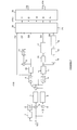
- FIG. 6 this is a block diagram of the receiving section of a wireless LAN transceiver.
- An antenna 100 is coupled to a down-converter 102 for demodulating the received signal and producing an intermediate frequency (IF) signal.
- the IF signal is passed to an IF-to-baseband converter 104 which produces at its output complex data samples which are delivered to a fast Fourier transform (FFT) circuit 106.
- FFT fast Fourier transform
- the down-converting operation and the IF-to-baseband conversion operation are controlled by a sampling clock generator and frequency synchronising circuit 108.
- a preamble detection circuit 110 receives the complex data samples from the IF-to-baseband converter 104 and is arranged to detect predetermined data sequences forming different preambles and in response thereto to generate controlling signals. For example, by detecting the time at which a preamble is received, it is possible for the preamble detector 110 to estimate a timing error and in response thereto provide a value representing the error on lines 112 and 114 to the generator 108 and the FFT circuit 106. The detector 110 can also provide a "preamble detected" output on line 116.
- the preamble detector 110 comprises an auto-correlation circuit 118 for auto-correlating the data samples received from the converter 104 and in response thereto generating various output values.
- the detector also comprises a processor 120 which receives the output values from the auto-correlator 118 and which includes a state machine for determining whether or not they are representative of a predetermined data sequence representing a preamble.
- the auto-correlator 118 receives complex data samples at input 122. These are sent to a 16 sample delay circuit 1 and then to a conjugator 2, which forms a complex conjugate of the output of the delay circuit 1.
- a multiplier 3 multiplies the delayed complex conjugate with the input samples received from input 122 and produces an output representing an auto-correlation of the input to a moving average circuit 5. This produces at its output a signal representing a moving average of the auto-correlation output, the average being based on a sliding window of 48 samples.
- the input data samples are also provided to a power detecting circuit 4, the output of which is delivered to a moving average circuit 6, which is also based on a sliding window of 48 samples.
- the normalisation results in the peak of the auto-correlation output always being unity, i.e. '1'.
- the output of the divider 7 is delivered to a circuit 8 which calculates the modulus of the auto-correlation function.
- the circuit 8 could be a programmable read-only memory (PROM).
- PROM programmable read-only memory
- is then provided by circuit 8 as a first output O1 of the auto-correlator 118.
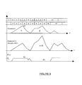
- Figures 8 to 10 show, for respectively the broadcast burst, ULCH and USCH preambles, the input data samples, the delayed data samples and the modulus of the auto-correlation magnitude
- the modulus of the auto-correlation function is also fed to an 80-sample delay circuit 10, the output
- the output signals are summed by an adder 12, the output (
- Figures 8 and 9 show
- the complex data output of the divider 7 is also delivered to a phase angle calculator 9, which may also be a PROM. This calculates the phase angle of the auto-correlation function and delivers the result to a quadrant corrector 11.
- the quadrant corrector also receives the complex data samples from the divider 7, and by examining the signs of the real and imaginary parts determines the quadrant within which the phase angle occurs. The resulting corrected phase angle is then delivered to a limiter 15.
- the output of the limiter 15 is fed to a moving average circuit 17, the output P(n) of which forms a fourth output 04 of the auto-correlation circuit 118.
- Figures 8 to 10 show this output P(n) for respectively the broadcast burst, ULCH and USCH preambles.
- the output of the quadrant corrector 11 is also fed to an 80 sample delay circuit 14, and then to limiter circuit 16 and moving average circuit 18, which operate in the same manner as circuits 15 and 17 respectively, to produce output O5.
- P(n) is representative not of the phase of the instantaneous auto-correlation function, but of the phase of the sliding mean of the auto-correlation function (derived from moving average circuit 5).
- the length of the moving average in this case 48 samples) significantly influences the size and location of the waveform P(n).
- P(n) is itself based on a moving average of the phase output, derived by moving average circuit 17.
- the shape and location of P(n) would be influenced by the characteristics of this circuit 17 and any delay which may be introduced by the circuit. Similar comments apply to the P(n-80) waveform.
- the outputs O1 to O5 thus represent the following:
- the processor circuit 120 comprises an input selector 19 and a state machine 20.
- the input selector 19 receives the outputs O1 to O5 from the auto-correlator 118.
- the input selector also receives a configuration input on lines 21, which is used for selecting the preamble to be detected.
- the input selector couples the values received from outputs O1 to O5 to inputs I1 to I5 of the state machine 20 in different ways depending on the values of the signals at configuration inputs 21.
- the state machine 20 is operable to carry out a predetermined algorithm on the values received at inputs I1 to I5 in order to generate the timing error signal on lines 112, 114 and the preamble detection signal on line 116.
- the general operation of the state machine 20 will be described with reference to the flowchart of Figure 11.
- the main function of preamble detection is achieved by determining when the input signal I1 has reached a peak under conditions representing the presence of a particular preamble type.
- the state machine leaves a reset state at step 1000 when it is activated by detecting an input control window.
- an internal "previous maximum" variable PM is set equal to a predetermined threshold T.
- the state machine checks the values of a number of inputs. In particular, depending upon the preamble being detected, the state machine will check one or more of the values of the outputs O1 to O5 of the auto-correlation circuit 118. Unless certain conditions are met, the state machine then loops back to step 1010.
- the conditions being checked are:
- Tests 1 to 3 are used for checking auto-correlation magnitudes, and test 4 and 5 for auto-correlation phases.
- variable PM is set equal to the input value I1.
- An internal count variable CT is set equal to zero.
- step 1016 The state machine proceeds to step 1016 to check whether the variable I1 has become smaller than the variable PM. If it has not yet become smaller (that is if the input variable I1 is still increasing towards a peak) then the program proceeds to step 1018. At this step, the state machine checks that the values of the other variables (which were previously checked at step 1012) are still indicative of the correct conditions for detecting a peak. If so, the state machine returns to step 1014. Otherwise, the state machine returns to step 1010, so that it returns to its initial state of checking for appropriate conditions.
- the state machine passes through steps 1014, 1016 and 1018 until the value of the input variable I1 becomes less than the variable PM (i.e. until after the peak value of the variable I1 has been passed).
- step 1020 The state machine then proceeds to step 1020 to check whether the count variable CT is equal to a predetermined value N m . If not, the program proceeds to step 1022, to increment the value of CT, and then reverts to step 1016 to check that the input I1 is still less than the variable PM. The machine continues in this state, looping through steps 1016, 1020 and 1022, until CT reaches the value N m , at which point the state machine proceeds to step 1024, which indicates that the state machine has detected a peak which is of sufficient magnitude, and which occurs in the correct conditions, to represent a predetermined preamble.
- the state machine 20 issues a peak detection signal on line 116, and an error signal on line 112 and 114.
- the error signal is representative of a timing error and is determined by the difference between the number of samples that have passed since the control window was activated and N m .
- the input selector 19 is set so that the inputs of the state machine 20 receive the following values:
- test 3 will always be met.
- the other four tests will be met when the maximum value of the A+B peak ( Figure 8) is approached.
- the phase value P(n) is equal to 0, so that condition 5 is met, as shown at 60.
- the delayed phase value P(n-80) would have the value shown at 62, and therefore would meet condition 4.
- would have the value shown at 64, and therefore would meet the condition 2.
- the state machine 20 locates the peak by continually comparing the current sample with N m previous samples, making use of both magnitude and phase to start the operation.
- a provisional peak is detected when an auto-correlation output exceeds a given threshold in the correct phase condition.
- a new input is then compared with the provisional peak. If the new input is larger than the provisional peak, the new input becomes the provisional peak.
- the peak is detected when the provisional peak remains the largest, for a predefined number of samples and when the previous N p phase samples are within a selected tolerance, i.e. if the phase is correct, according to the relevant standard (HIPERLAN/2, IEE802.11a, MMAC etc).
- a suitable value for T in HIPERLAN/2 would be 0.4 (auto-correlation circuit normalised output) and 32 for N m .
- the position of the first maximum i.e. the A peak
- the maximum would be situated 64 samples after the beginning of the preamble.
- the remainder of the receiver processing such as frequency synchronization, sample clock synchronization and data demodulation may proceed.
- the input selector 19 presents the following values to the inputs I1 to 5 of state machine 20:
- the state machine will be checking for the maximum value 70 of the (
- the input selector 19 is arranged to provide the following values to the inputs I1 to I5:
- the state machine is arranged to detect ULCH and USCH preambles only when other conditions indicate that they may appear (for example after first detecting a broadcast burst preamble).
- the invention may be implemented using discrete hardware or a programmed microprocessor.
Priority Applications (3)
| Application Number | Priority Date | Filing Date | Title |
|---|---|---|---|
| EP01306645A EP1282257A1 (fr) | 2001-08-02 | 2001-08-02 | Dispositif et méthode de détection de séquences de données |
| JP2002224992A JP2003143106A (ja) | 2001-08-02 | 2002-08-01 | 受信信号中の所定の複素数データシーケンスを検出する方法および装置並びに無線lan受信機 |
| US10/210,103 US7415080B2 (en) | 2001-08-02 | 2002-08-02 | Method and apparatus for detecting data sequences |
Applications Claiming Priority (1)
| Application Number | Priority Date | Filing Date | Title |
|---|---|---|---|
| EP01306645A EP1282257A1 (fr) | 2001-08-02 | 2001-08-02 | Dispositif et méthode de détection de séquences de données |
Publications (1)
| Publication Number | Publication Date |
|---|---|
| EP1282257A1 true EP1282257A1 (fr) | 2003-02-05 |
Family
ID=8182166
Family Applications (1)
| Application Number | Title | Priority Date | Filing Date |
|---|---|---|---|
| EP01306645A Withdrawn EP1282257A1 (fr) | 2001-08-02 | 2001-08-02 | Dispositif et méthode de détection de séquences de données |
Country Status (3)
| Country | Link |
|---|---|
| US (1) | US7415080B2 (fr) |
| EP (1) | EP1282257A1 (fr) |
| JP (1) | JP2003143106A (fr) |
Cited By (4)
| Publication number | Priority date | Publication date | Assignee | Title |
|---|---|---|---|---|
| EP1638283A1 (fr) * | 2004-09-17 | 2006-03-22 | Samsung Electronics Co.,Ltd. | Méthode et appareil d'extraction d'un signal de synchronisation de trame dans un système de communication |
| WO2008002091A1 (fr) | 2006-06-28 | 2008-01-03 | Samsung Electronics Co., Ltd. | Système et procédé de communication sans fil de vidéo non comprimée comprenant un modèle de préambule |
| WO2008095731A1 (fr) * | 2007-02-08 | 2008-08-14 | Nokia Corporation | Synchronisation robuste pour un signal duplex à répartition dans le temps |
| US7453857B2 (en) | 2003-05-09 | 2008-11-18 | Koninklijke Philips Electronics N.V. | Measuring medium activity patterns in wireless networks and deriving information from the activity patterns |
Families Citing this family (40)
| Publication number | Priority date | Publication date | Assignee | Title |
|---|---|---|---|---|
| US7952511B1 (en) | 1999-04-07 | 2011-05-31 | Geer James L | Method and apparatus for the detection of objects using electromagnetic wave attenuation patterns |
| US7916803B2 (en) | 2003-04-10 | 2011-03-29 | Qualcomm Incorporated | Modified preamble structure for IEEE 802.11a extensions to allow for coexistence and interoperability between 802.11a devices and higher data rate, MIMO or otherwise extended devices |
| US8743837B2 (en) | 2003-04-10 | 2014-06-03 | Qualcomm Incorporated | Modified preamble structure for IEEE 802.11A extensions to allow for coexistence and interoperability between 802.11A devices and higher data rate, MIMO or otherwise extended devices |
| KR100582906B1 (ko) | 2003-12-27 | 2006-05-23 | 한국전자통신연구원 | 무선 랜 시스템을 위한 프리앰블 구성 방법 및 프레임동기 검출 방법 |
| US8724447B2 (en) | 2004-01-28 | 2014-05-13 | Qualcomm Incorporated | Timing estimation in an OFDM receiver |
| US8433005B2 (en) * | 2004-01-28 | 2013-04-30 | Qualcomm Incorporated | Frame synchronization and initial symbol timing acquisition system and method |
| CN1939026B (zh) * | 2004-01-28 | 2012-07-04 | 高通股份有限公司 | Ofdm接收机中的定时估计 |
| JP4838241B2 (ja) | 2004-05-27 | 2011-12-14 | クゥアルコム・インコーポレイテッド | Ieee802.11a装置間における相互動作のための変更されたieee802.11a |
| US7418065B2 (en) * | 2004-09-29 | 2008-08-26 | Intel Corporation | Multicarrier receivers and methods for detecting cyclic prefixes having unknown lengths |
| US7539241B1 (en) * | 2004-10-22 | 2009-05-26 | Xilinx, Inc. | Packet detector for a communication system |
| KR100655660B1 (ko) | 2004-12-16 | 2006-12-11 | 한국전자통신연구원 | 무선랜 프리앰블 신호 검출 장치 및 그의 신호 검출 및타이밍 검출 방법 |
| KR100579531B1 (ko) * | 2005-01-28 | 2006-05-15 | 삼성전자주식회사 | Ofdm 수신기에 적용되는 심볼시간 동기 장치 및 그 방법 |
| JP4531581B2 (ja) | 2005-02-09 | 2010-08-25 | 株式会社エヌ・ティ・ティ・ドコモ | 無線通信用送受信装置における制御装置及び無線通信用送受信方法 |
| US7542522B2 (en) * | 2005-09-20 | 2009-06-02 | Intel Corporation | Device, system and method of wireless signal detection |
| US7590184B2 (en) * | 2005-10-11 | 2009-09-15 | Freescale Semiconductor, Inc. | Blind preamble detection for an orthogonal frequency division multiplexed sample stream |
| US7710919B2 (en) * | 2005-10-21 | 2010-05-04 | Samsung Electro-Mechanics | Systems, methods, and apparatuses for spectrum-sensing cognitive radios |
| US7668262B2 (en) * | 2005-10-21 | 2010-02-23 | Samsung Electro-Mechanics | Systems, methods, and apparatuses for coarse spectrum-sensing modules |
| US20070092045A1 (en) * | 2005-10-21 | 2007-04-26 | Wangmyong Woo | Systems, Methods, and Apparatuses for Fine-Sensing Modules |
| US7869980B2 (en) * | 2005-11-03 | 2011-01-11 | International Business Machines Corporation | Using statistics to locate signals in noise |
| US7623599B2 (en) * | 2005-11-21 | 2009-11-24 | Freescale Semiconductor, Inc. | Blind bandwidth detection for a sample stream |
| US8144818B2 (en) * | 2005-12-15 | 2012-03-27 | Qualcomm Incorporated | Apparatus and methods for determining timing in a communication system |
| US7675844B2 (en) | 2006-02-24 | 2010-03-09 | Freescale Semiconductor, Inc. | Synchronization for OFDM signals |
| WO2007125846A1 (fr) | 2006-04-26 | 2007-11-08 | Panasonic Corporation | Dispositif et procede de detection de signal |
| US7852972B2 (en) | 2006-05-22 | 2010-12-14 | Qualcomm Incorporated | Single-burst acquistion for wireless communication system |
| US20080025197A1 (en) * | 2006-07-28 | 2008-01-31 | Mccoy James W | Estimating frequency error of a sample stream |
| KR100937423B1 (ko) * | 2006-09-26 | 2010-01-18 | 엘지전자 주식회사 | 반복형 시퀀스 생성 방법 및 이를 이용한 신호 송신 방법 |
| US7860197B2 (en) * | 2006-09-29 | 2010-12-28 | Samsung Electro-Mechanics | Spectrum-sensing algorithms and methods |
| KR100789921B1 (ko) | 2006-11-07 | 2008-01-02 | 한국전자통신연구원 | Ofdm 시스템에서의 프리엠블 패킷 검출 장치 및 그방법 |
| KR100809020B1 (ko) * | 2006-12-08 | 2008-03-03 | 한국전자통신연구원 | 이동 통신 시스템에서의 단말기의 초기 동기 획득 장치 및그 방법 |
| KR100897527B1 (ko) | 2007-12-10 | 2009-05-15 | 한국전자통신연구원 | 직교주파수 분할 다중화 신호의 패킷 검출 장치 및 그 방법 |
| US7965799B2 (en) * | 2008-02-25 | 2011-06-21 | Xilinx, Inc. | Block boundary detection for a wireless communication system |
| JP4572968B2 (ja) * | 2008-08-06 | 2010-11-04 | ソニー株式会社 | パケット検出装置及びパケット検出方法、無線通信装置及び無線通信方法、並びにコンピューター・プログラム |
| US8605604B1 (en) * | 2009-12-23 | 2013-12-10 | Marvell International Ltd. | WLAN module test system |
| CN102823211A (zh) * | 2010-03-29 | 2012-12-12 | 株式会社村田制作所 | 无线通讯系统中整数载波频率偏移估计的方法及装置 |
| JP5477480B2 (ja) * | 2010-03-29 | 2014-04-23 | 株式会社村田製作所 | 無線通信システムにおける正確な時間同期用の方法および装置 |
| US8824607B2 (en) | 2010-07-01 | 2014-09-02 | Intelleflex Corporation | Subcarrier frequency acquisition and complex derotation to baseband |
| JP5410478B2 (ja) * | 2011-07-07 | 2014-02-05 | クゥアルコム・インコーポレイテッド | 1またはそれ以上の受信器を備えた無線通信システムにおける統合パケット検出 |
| WO2016022962A1 (fr) * | 2014-08-07 | 2016-02-11 | ONE Media, LLC | Configuration dynamique d'une trame flexible de données de transport/phy à multiplexage par répartition orthogonale de la fréquence |
| KR20170051437A (ko) | 2014-08-07 | 2017-05-11 | 코히어런트 로직스, 인코포레이티드 | 멀티-파티션 라디오 프레임 |
| US9985744B2 (en) * | 2015-07-30 | 2018-05-29 | Cohda Wireless Pty Ltd. | Wireless receiver |
Citations (2)
| Publication number | Priority date | Publication date | Assignee | Title |
|---|---|---|---|---|
| US5282227A (en) * | 1992-05-21 | 1994-01-25 | The Titan Corporation | Communication signal detection and acquisition |
| WO2000059147A1 (fr) * | 1999-03-26 | 2000-10-05 | Telefonaktiebolaget Lm Ericsson (Publ) | Procede de synchronisation efficace dans un systeme de communications |
Family Cites Families (7)
| Publication number | Priority date | Publication date | Assignee | Title |
|---|---|---|---|---|
| US5758277A (en) * | 1996-09-19 | 1998-05-26 | Corsair Communications, Inc. | Transient analysis system for characterizing RF transmitters by analyzing transmitted RF signals |
| US6141373A (en) * | 1996-11-15 | 2000-10-31 | Omnipoint Corporation | Preamble code structure and detection method and apparatus |
| US6064695A (en) * | 1997-06-20 | 2000-05-16 | Itran Communications Ltd. | Spread spectrum communication system utilizing differential code shift keying |
| DE69909589T2 (de) * | 1999-04-12 | 2004-06-03 | Sony International (Europe) Gmbh | Kommunikationsvorrichtung und Verfahren zum Unterscheiden zwischen unterschiedlichen Datenbursten in einem digitalen Telekommunikationssystem |
| US6785350B1 (en) * | 1999-10-14 | 2004-08-31 | Nokia Corporation | Apparatus, and associated method, for detecting a symbol sequence |
| US20020065047A1 (en) * | 2000-11-30 | 2002-05-30 | Moose Paul H. | Synchronization, channel estimation and pilot tone tracking system |
| JP3636145B2 (ja) * | 2001-06-15 | 2005-04-06 | ソニー株式会社 | 復調タイミング生成回路および復調装置 |
-
2001
- 2001-08-02 EP EP01306645A patent/EP1282257A1/fr not_active Withdrawn
-
2002
- 2002-08-01 JP JP2002224992A patent/JP2003143106A/ja active Pending
- 2002-08-02 US US10/210,103 patent/US7415080B2/en active Active
Patent Citations (2)
| Publication number | Priority date | Publication date | Assignee | Title |
|---|---|---|---|---|
| US5282227A (en) * | 1992-05-21 | 1994-01-25 | The Titan Corporation | Communication signal detection and acquisition |
| WO2000059147A1 (fr) * | 1999-03-26 | 2000-10-05 | Telefonaktiebolaget Lm Ericsson (Publ) | Procede de synchronisation efficace dans un systeme de communications |
Cited By (7)
| Publication number | Priority date | Publication date | Assignee | Title |
|---|---|---|---|---|
| US7453857B2 (en) | 2003-05-09 | 2008-11-18 | Koninklijke Philips Electronics N.V. | Measuring medium activity patterns in wireless networks and deriving information from the activity patterns |
| EP1638283A1 (fr) * | 2004-09-17 | 2006-03-22 | Samsung Electronics Co.,Ltd. | Méthode et appareil d'extraction d'un signal de synchronisation de trame dans un système de communication |
| US7711074B2 (en) | 2004-09-17 | 2010-05-04 | Samsung Electronics Co., Ltd. | Sync extraction apparatus in communication system and method thereof |
| WO2008002091A1 (fr) | 2006-06-28 | 2008-01-03 | Samsung Electronics Co., Ltd. | Système et procédé de communication sans fil de vidéo non comprimée comprenant un modèle de préambule |
| EP2033386A1 (fr) * | 2006-06-28 | 2009-03-11 | Samsung Electronics Co., Ltd. | Système et procédé de communication sans fil de vidéo non comprimée comprenant un modèle de préambule |
| EP2033386A4 (fr) * | 2006-06-28 | 2015-04-15 | Samsung Electronics Co Ltd | Système et procédé de communication sans fil de vidéo non comprimée comprenant un modèle de préambule |
| WO2008095731A1 (fr) * | 2007-02-08 | 2008-08-14 | Nokia Corporation | Synchronisation robuste pour un signal duplex à répartition dans le temps |
Also Published As
| Publication number | Publication date |
|---|---|
| US7415080B2 (en) | 2008-08-19 |
| JP2003143106A (ja) | 2003-05-16 |
| US20030067999A1 (en) | 2003-04-10 |
Similar Documents
| Publication | Publication Date | Title |
|---|---|---|
| US7415080B2 (en) | Method and apparatus for detecting data sequences | |
| US7627059B2 (en) | Method of robust timing detection and carrier frequency offset estimation for OFDM systems | |
| US7515663B2 (en) | Method and apparatus for synchronising receivers | |
| US6993084B1 (en) | Coarse frequency synchronisation in multicarrier systems | |
| EP1188266B1 (fr) | Dispositif de synchronisation de frequence et de temporisation de symboles pour signaux ofdm et procede associe | |
| EP2439973B1 (fr) | Procédé et appareil de détection basés sur un processus d accès aléatoire | |
| US8064546B2 (en) | Random access preamble detection for long term evolution wireless networks | |
| US7426175B2 (en) | Method and apparatus for pilot signal transmission | |
| EP1698121B1 (fr) | Amélioration de synchronisation et d'estimation du canal dans des systèmes de communication de type WLAN en utilisant un préambule à structure modifiée | |
| EP2501064B1 (fr) | Procédé d'estimation de décalage de fréquence et dispositif de communication, système de communication sans fil et programme | |
| EP2804356B1 (fr) | Procédé et appareil d'accès aléatoire dans un système de communication | |
| US20090190675A1 (en) | Synchronization in a broadcast ofdm system using time division multiplexed pilots | |
| US20050063298A1 (en) | Synchronization in a broadcast OFDM system using time division multiplexed pilots | |
| US7778153B2 (en) | Method for estimating transmission delay and receiver using the same | |
| EP2612478A1 (fr) | Procédés et appareil pour estimation de décalage de fréquence porteuse et correction de décalage de fréquence porteuse | |
| US8270509B2 (en) | Determining a frequency error in a receiver of a wireless communications system | |
| WO2008097150A1 (fr) | Structure de préambule pour une synchronisation et recherche de cellules | |
| US6862297B1 (en) | Wide range frequency offset estimation in OFDM systems | |
| Almenar et al. | Synchronization techniques for HIPERLAN/2 | |
| US7826544B2 (en) | OFDM signal acquisition | |
| KR20100070377A (ko) | 시간 분할 멀티플렉싱된 파일럿을 사용한 브로드캐스트 ofdm 시스템에서의 동기화 | |
| CN101674280B (zh) | 检测ofdm符号时偏和频偏的方法 |
Legal Events
| Date | Code | Title | Description |
|---|---|---|---|
| PUAI | Public reference made under article 153(3) epc to a published international application that has entered the european phase |
Free format text: ORIGINAL CODE: 0009012 |
|
| AK | Designated contracting states |
Designated state(s): AT BE CH CY DE DK ES FI FR GB GR IE IT LI LU MC NL PT SE TR |
|
| AX | Request for extension of the european patent |
Extension state: AL LT LV MK RO SI |
|
| 17P | Request for examination filed |
Effective date: 20030801 |
|
| AKX | Designation fees paid |
Designated state(s): DE FR GB |
|
| RAP1 | Party data changed (applicant data changed or rights of an application transferred) |
Owner name: MITSUBISHI DENKI KABUSHIKI KAISHA Owner name: MITSUBISHI ELECTRIC INFORMATION TECHNOLOGY CENTRE |
|
| 17Q | First examination report despatched |
Effective date: 20070330 |
|
| STAA | Information on the status of an ep patent application or granted ep patent |
Free format text: STATUS: THE APPLICATION IS DEEMED TO BE WITHDRAWN |
|
| 18D | Application deemed to be withdrawn |
Effective date: 20130301 |