EP1282009A2 - Beheizte, segmentierte Entwicklungstrommel - Google Patents
Beheizte, segmentierte Entwicklungstrommel Download PDFInfo
- Publication number
- EP1282009A2 EP1282009A2 EP02077968A EP02077968A EP1282009A2 EP 1282009 A2 EP1282009 A2 EP 1282009A2 EP 02077968 A EP02077968 A EP 02077968A EP 02077968 A EP02077968 A EP 02077968A EP 1282009 A2 EP1282009 A2 EP 1282009A2
- Authority
- EP
- European Patent Office
- Prior art keywords
- drum
- path
- electrical heater
- segments
- media
- Prior art date
- Legal status (The legal status is an assumption and is not a legal conclusion. Google has not performed a legal analysis and makes no representation as to the accuracy of the status listed.)
- Withdrawn
Links
- 238000001931 thermography Methods 0.000 claims abstract description 12
- 230000003213 activating effect Effects 0.000 claims abstract description 5
- 239000004020 conductor Substances 0.000 claims abstract description 5
- 229910052782 aluminium Inorganic materials 0.000 claims description 5
- XAGFODPZIPBFFR-UHFFFAOYSA-N aluminium Chemical compound [Al] XAGFODPZIPBFFR-UHFFFAOYSA-N 0.000 claims description 5
- 238000010438 heat treatment Methods 0.000 claims description 5
- 229920001296 polysiloxane Polymers 0.000 claims description 2
- 239000002131 composite material Substances 0.000 claims 1
- 229910052751 metal Inorganic materials 0.000 claims 1
- 239000002184 metal Substances 0.000 claims 1
- 239000010410 layer Substances 0.000 description 13
- 238000000034 method Methods 0.000 description 6
- 229910052709 silver Inorganic materials 0.000 description 5
- 239000004332 silver Substances 0.000 description 5
- BQCADISMDOOEFD-UHFFFAOYSA-N Silver Chemical compound [Ag] BQCADISMDOOEFD-UHFFFAOYSA-N 0.000 description 4
- 230000008569 process Effects 0.000 description 4
- 238000001816 cooling Methods 0.000 description 3
- 230000004907 flux Effects 0.000 description 3
- 230000008859 change Effects 0.000 description 2
- 238000002059 diagnostic imaging Methods 0.000 description 2
- 238000010586 diagram Methods 0.000 description 2
- 230000000694 effects Effects 0.000 description 2
- 238000005516 engineering process Methods 0.000 description 2
- 238000003384 imaging method Methods 0.000 description 2
- FOIXSVOLVBLSDH-UHFFFAOYSA-N Silver ion Chemical compound [Ag+] FOIXSVOLVBLSDH-UHFFFAOYSA-N 0.000 description 1
- 239000011230 binding agent Substances 0.000 description 1
- 230000015572 biosynthetic process Effects 0.000 description 1
- 238000007664 blowing Methods 0.000 description 1
- 239000003638 chemical reducing agent Substances 0.000 description 1
- 238000007796 conventional method Methods 0.000 description 1
- 239000002355 dual-layer Substances 0.000 description 1
- 239000007788 liquid Substances 0.000 description 1
- 230000010355 oscillation Effects 0.000 description 1
- 229920000728 polyester Polymers 0.000 description 1
- 230000005855 radiation Effects 0.000 description 1
- 230000004044 response Effects 0.000 description 1
- 150000003839 salts Chemical class 0.000 description 1
- -1 silver halide Chemical class 0.000 description 1
- 238000004088 simulation Methods 0.000 description 1
- 239000002356 single layer Substances 0.000 description 1
- 230000036962 time dependent Effects 0.000 description 1
Images
Classifications
-
- G—PHYSICS
- G03—PHOTOGRAPHY; CINEMATOGRAPHY; ANALOGOUS TECHNIQUES USING WAVES OTHER THAN OPTICAL WAVES; ELECTROGRAPHY; HOLOGRAPHY
- G03D—APPARATUS FOR PROCESSING EXPOSED PHOTOGRAPHIC MATERIALS; ACCESSORIES THEREFOR
- G03D13/00—Processing apparatus or accessories therefor, not covered by groups G11B3/00 - G11B11/00
- G03D13/002—Heat development apparatus, e.g. Kalvar
Definitions
- This invention relates in general to thermographic imaging systems and more particularly to improved processing temperature uniformity in heated drum processors for thermally processed thermographic imaging media.
- Photothermography is an established imaging technology.
- a photosensitive media is exposed to radiation to create a latent image which can then be thermally processed to develop the latent image.
- Devices and methods for implementing this thermal development process are generally known and include contacting the imaged photosensitive media with a heated platen, drum or belt, blowing heated air onto the media, immersing the media in a heated inert liquid and exposing the media to radiant energy of a wavelength to which the media is not photosensitive, e.g., infrared.
- the use of heated drums is particularly common.
- a common photosensitive media useable in these imaging processes is known as a photothermographic media, such as film and paper.
- a photothermographic media such as film and paper.
- One photothermographic media has a binder, silver halide, organic salt of silver (or other deducible, light-insensitive silver source), and a reducing agent for the silver ion.
- these photothermographic media are known as dry silver media, including dry silver film.
- thermographic media In order to precisely heat exposed photothermographic media, including film and paper, it has been found to be desirable to use electrically heated drums.
- An apparatus employing this technique a cylindrical drum is heated to a temperature near the desired development temperature of the photothermographic media.
- the photothermographic media is held in close proximity to the heated drum as the drum is rotated about its longitudinal axis.
- the temperature of the surface of the heated drum is known, the portion of the circumference around which the photothermographic media is held in close proximity is known and the rate of rotation of the drum is known, the development time and temperature of the thermographic media can be determined.
- these parameters are optimized for the particular photothermographic media utilized and, possibly, for the application in which the photothermographic media is employed.
- U.S. Patent 5,580,478, issued December 3, 1996, inventors Tanamachi et al. discloses a temperature controlled, electrically heated drum for developing exposed photothermographic media.
- a cylindrical drum has a surface and is rotatable on an axis.
- An electrical heater is thermally coupled to the surface of the cylindrical drum.
- the present medical imaging film used can draw relatively significant amounts of heat from the processor drum surface as it first contacts the drum and warms up.
- Current drum processors typically use a circumambient (circumferentially uniform) internal drum heater.
- Normal heating devices include resistive element blanket heaters attached to the drum or lamp type radiative devices located in the drum core. Circumambient heaters can cause locations of the drum to under heat and over heat when film enters the processor. In locations of early film contact, where the most significant heat load takes place, the drum temperature can decrease while in other locations the drum temperature can increase because it is not loaded as much. The temperature controller does not correct this.
- the drum temperature can be controlled to a tight temperature variation at a location on the drum, but the overall drum temperature will still vary because of the non-even heat load as the film is applied to the drum.
- thermographic imaging system in which exposed thermographic imaging media is moved along a path
- apparatus comprising; a movable member of thermally conductive material located along said path, said member having a first dimension parallel to said path and a second dimension perpendicular to said path, said member having a first side which thermally contacts media moved along said path and a second opposite side; a first electrical heater in thermal contact with said second side of said member; a second electrical heater in thermal contact with said second side of said member, said second electrical heater having a plurality of separately activated segments extending in said first dimension; and a control for selectively activating said segments as media is moved along said path into contiguity with each said segments.
- the invention has the following advantages.
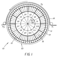
- Fig. 1 is a diagrammatic view of an embodiment of the present invention.
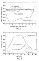
- Figs. 2 and 3 are graphical views useful in explaining the operation of the present invention.
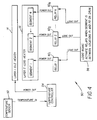
- Fig. 4 is a block diagram of a control logic system for the present invention.
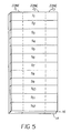
- Fig. 5 is a diagrammatic view of another embodiment of the present invention.
- an improved heated drum for thermally processing exposed thermographic imaging media. Improved processing temperature uniformity has resulted in improved media uniformity.
- the heated drum includes a first electrical heater which extends around the drum's internal circumference and which is activated substantially continuously.
- a second electrical heater extends around the drum's internal circumference but is circumferentially segmented so that segments are activated as media comes into contact with the drum.
- heater drum 10 includes a cylindrical drum 12 of thermally conductive material such as aluminum.
- a first electrical heater 14 (layer 1) and second electrical heater 16 (layer 2) are in thermal contact with the inner surface 19 of drum 12.
- electrical heater 16 includes twelve circumferentially positioned segments S 1 , ...., S 12 , which are individually activated as media 18 comes into contact with the outer surface 20 of drum 10.
- Drum 10 has a first or circumference dimension parallel to the path of movement of a media 18 in contact with drum 10 and a second or width dimension perpendicular to the first dimension.
- the drum 10 operates typically under two different states: idle and load.
- the idle state is the case where there is no film 18 contacting drum 10, and the load state is the case where film 18 is contacting the drum 10.
- the idle layer (layer 1) 14 represents the current technology where, for example three heater zones coexist with three RTD sensors connected to independent temperature controllers as shown in Fig. 5, heaters 14, 16 are depicted in a stretched out state before formation into cylinders affixed to the inner surface 19 of drum 12.
- the three zones are for the left, center and right crossweb locations along the drum 10.
- Each zone (Z 1 , Z 2 , Z 3 ) in the idle layer 14 has a constant heat flux pattern along the downweb or circumferential direction.
- the load heater layer (layer 2) 16 provides the extra heat energy needed when the film 18 is being processed.
- This layer 16 is broken into load segments or zones around the drum's circumference.
- Fig. 1 shows the segments broken into 12 arcs (S 1 , S 2 , ..., S 12 ), each 30 degrees in angle.
- the segment number total depends on the drum's rotation speed, diameter and heat load and was optimized through trial and error in this case.
- the first load segment (S 1 ) activates nearest to the film's lead edge.
- the second load segment (S 2 ) activates when the film reaches it.
- a time dependent, two dimensional finite element model was constructed. It simulated an eight inch round thermal processor heating an eight mil. thick, 17 inch long sheet of polyester base film in the downweb direction.
- the drum was made of aluminum and was 0.25 inches thick. It used a dual layer idle and load segmented heater attached to the inner aluminum surface of the drum. The load heater was segmented into 12 arcs like Fig. 1 shows.
- a discreet proportional controller was simulated to control the drum temperature. In the model, the controller responded by measuring the average temperature around the inner aluminum circumference of the drum. The proportional bandwidth and controller cycle time were optimized to reduce controller temperature variation. No temperature sensors were needed for the load heater layer because this layer is only activated by film presence. Film was applied to the drum using gap conduction elements in the locations of contact.
- the film's wrap angle about the drum was 180 degrees (between P1 and P3 in Fig. 1).
- the silicone surface of the drum and the film were subjected to air convection boundary conditions modeled after Newton's cooling law to simulate normal heat loss in their respective environments.
- the air convection boundary conditions were applied uniformly to the drum and film surface. In locations where the film was in contact with the drum, the convection on the film from that surface was removed.
- the ambient temperature of the film was lower than the drum.
- Fig. 2 Four heater configuration results are graphed from the numerical model in Fig. 2.
- the horizontal axis represents the length of film processed from head to tail. The film was 17 inches long.
- the vertical axis represents the final temperature the film reached on the drum just as it detached from the drum surface (finished processing). This graph essentially shows how uniform a piece of film is processed on the drum. The flatter the line, the more uniform it is processed.
- the first case is the Uniform Heater. This would be the style of drum 10 with a circumambient heat flux single layer blanket heater 14 attached to the inner surface of the drum 10.
- the film temperature begins to fall as the film 18 is processed after which the temperature then increases at a slow then faster rate.
- the initial temperature fall off is a response to the drum 10 being cooled by the film in a localized region and the temperature controller increasing its duty cycle to counteract.
- the entire inner surface of the drum 10 is heated. Because only a local region is cooling, the controller does not respond as strong as necessary.
- the controller continues to heat the drum 10.
- This heating effect catches up as new film 18 is applied and eventually the new film is warmed to a higher temperature than the previous section film 18 because the drum's temperature is increasing where new film 18 is being applied.
- the effect is very prominent for the tail section of film 18 because a significant section of the drum 10 has now been heated but no new film 18 is being applied and cooling the drum 10. The hottest section of the drum 10 heats the last section of film 18.
- the second and third case results add a segmented load heater 16.
- One has 60 degree arc segments and the second has 30 degree arc segments.
- the segments as discussed previously switch on one-by-one as the film 18 is loaded onto the drum 10.
- Two segments are powered on for the 30 degree and one single segment for the 60 degree heater.
- the amount of power produced by the load heater segments turned on is set to ideally equal the amount of power the film 18 draws from the drum 10.
- Heat flux values for the load heater segments are then derived from this requirement. Once the film's tail edge passes the midpoint of the last heater zone segment that contacts it, the load heater switching sequence terminates.
- the 30 degree segment version produce very uniform processed film.
- the 60 degree case appeared to produce a temperature oscillation pattern that was not as optimal but still better than the original uniform heater.
- segmented heater reduces the duty cycle variation for the controller.
- the temperature controller monitors the two distinct load states of idle and load. The controller naturally increases its duty cycle when the load state occurs. The amount it increases is a function of how much more power is necessary and how much power is available.
- the load heater reduces the duty cycle change of the controller between states.
- Fig. 3 shows the heater duty cycles for the first three case results presented.
- the film 18 contacts the drum 10 at time zero.
- the film 18 dwells on the drum 10 for 15 seconds.
- the wrap angle and the film length were previously shown.
- the duty cycle increases from approximately 11 percent to 50 percent.
- the segmented heater cases reduced the duty cycle variation significantly.
- the duty cycle equaled the idle state value indicating that load heaters were matched to the film heat load.
- the 30 degree case was better than the 60 degree case.
- a sensor is needed to detect drum position.
- Another sensor is needed to detect film presence.
- the load heater would connect to a power controller with logic switches activating each segment when necessary.
- the duty cycle of this power controller either would be turned to a specific value depending on film load or actively adjusted based upon some feedback signal device.
- One feedback signal device is the idle heater duty cycle control value. As the idle heater duty cycle increased, the load duty cycle could increase and vice-versa.
- the idle heater duty cycle ideally does not change when the load heaters segments are activated when film is present.
- controller 50 includes temperature sensor 52, temperature controller 54, logic board 56 and relays 60 1 , 60 2 , ..., 60 N .
- Temperature sensor 52 provides the temperature of drum 10 to temperature controller 54 which controls the temperature of first electrical heater 14.
- Logic board 56 activates relays 60 1 , 60 2 , ..., 60 N to provide electrical power to segments 1, 2, ⁇ N when a segment of second electrical heater 16 (layer 2) is between locations P 1 , and P 2 on drum 10 (Fig. 1).
Landscapes
- Physics & Mathematics (AREA)
- General Physics & Mathematics (AREA)
- Photographic Developing Apparatuses (AREA)
Applications Claiming Priority (2)
| Application Number | Priority Date | Filing Date | Title |
|---|---|---|---|
| US09/918,888 US6411320B1 (en) | 2001-07-31 | 2001-07-31 | Segmented heated drum processor |
| US918888 | 2001-07-31 |
Publications (2)
| Publication Number | Publication Date |
|---|---|
| EP1282009A2 true EP1282009A2 (de) | 2003-02-05 |
| EP1282009A3 EP1282009A3 (de) | 2003-08-13 |
Family
ID=25441125
Family Applications (1)
| Application Number | Title | Priority Date | Filing Date |
|---|---|---|---|
| EP02077968A Withdrawn EP1282009A3 (de) | 2001-07-31 | 2002-07-19 | Beheizte, segmentierte Entwicklungstrommel |
Country Status (3)
| Country | Link |
|---|---|
| US (1) | US6411320B1 (de) |
| EP (1) | EP1282009A3 (de) |
| JP (1) | JP2003156828A (de) |
Cited By (1)
| Publication number | Priority date | Publication date | Assignee | Title |
|---|---|---|---|---|
| WO2006073659A1 (en) | 2005-01-05 | 2006-07-13 | Eastman Kodak Company | Thermal processor employing drum and flatbed technologies |
Families Citing this family (4)
| Publication number | Priority date | Publication date | Assignee | Title |
|---|---|---|---|---|
| JP2005331838A (ja) * | 2004-05-21 | 2005-12-02 | Konica Minolta Medical & Graphic Inc | 熱現像装置及び熱現像方法 |
| JP5038463B2 (ja) * | 2010-04-22 | 2012-10-03 | キヤノン株式会社 | シート乾燥装置およびプリント装置 |
| US20130215202A1 (en) * | 2012-02-22 | 2013-08-22 | Kevin David Koller | Helical dryer path for a print substrate web |
| US8749603B2 (en) * | 2012-06-12 | 2014-06-10 | Xerox Corporation | Inkjet printer having an image drum heating and cooling system |
Citations (1)
| Publication number | Priority date | Publication date | Assignee | Title |
|---|---|---|---|---|
| US5580478A (en) | 1994-05-09 | 1996-12-03 | Minnesota Mining And Manufacturing Company | Apparatus for controlling the temperature of and a moveable, electrically heated object using two way on axis optical communication |
Family Cites Families (7)
| Publication number | Priority date | Publication date | Assignee | Title |
|---|---|---|---|---|
| DE3400087C1 (de) * | 1984-01-03 | 1985-05-30 | J.M. Voith Gmbh, 7920 Heidenheim | Elektrisch heizbare Walze |
| US6007971A (en) * | 1992-09-09 | 1999-12-28 | Minnesota Mining And Manufacturing | Apparatus, system, and method for processing photothermographic elements |
| JPH06186877A (ja) * | 1992-10-21 | 1994-07-08 | Ricoh Co Ltd | 定着装置 |
| EP0886813B1 (de) * | 1996-03-12 | 2003-01-08 | TYCO Electronics Corporation | Elektrische heizsysteme |
| US5990461A (en) * | 1997-11-26 | 1999-11-23 | Eastman Kodak Company | Photothermographic media processor thermal control |
| DE69919645T2 (de) * | 1998-09-03 | 2005-09-15 | Fuji Photo Film Co., Ltd., Minami-Ashigara | Einrichtung zur thermischen Behandlung und damit erzeugte Wärmeentwicklungseinrichtung |
| JP2000321749A (ja) * | 1999-03-11 | 2000-11-24 | Konica Corp | 熱現像装置 |
-
2001
- 2001-07-31 US US09/918,888 patent/US6411320B1/en not_active Expired - Fee Related
-
2002
- 2002-07-19 EP EP02077968A patent/EP1282009A3/de not_active Withdrawn
- 2002-07-30 JP JP2002221351A patent/JP2003156828A/ja active Pending
Patent Citations (1)
| Publication number | Priority date | Publication date | Assignee | Title |
|---|---|---|---|---|
| US5580478A (en) | 1994-05-09 | 1996-12-03 | Minnesota Mining And Manufacturing Company | Apparatus for controlling the temperature of and a moveable, electrically heated object using two way on axis optical communication |
Cited By (2)
| Publication number | Priority date | Publication date | Assignee | Title |
|---|---|---|---|---|
| WO2006073659A1 (en) | 2005-01-05 | 2006-07-13 | Eastman Kodak Company | Thermal processor employing drum and flatbed technologies |
| US7317468B2 (en) | 2005-01-05 | 2008-01-08 | Carestream Health, Inc. | Thermal processor employing drum and flatbed technologies |
Also Published As
| Publication number | Publication date |
|---|---|
| US6411320B1 (en) | 2002-06-25 |
| JP2003156828A (ja) | 2003-05-30 |
| EP1282009A3 (de) | 2003-08-13 |
Similar Documents
| Publication | Publication Date | Title |
|---|---|---|
| US6411320B1 (en) | Segmented heated drum processor | |
| JPH09197863A (ja) | 定着装置 | |
| US6420685B1 (en) | Control of electrical heater to reduce flicker | |
| JP2021508916A (ja) | 熱処理ドラム | |
| JP2004247307A (ja) | 加熱器の温度制御システム | |
| JP5873691B2 (ja) | 放射加熱器を用いた熱処理装置 | |
| JPS61204666A (ja) | 熱ロ−ル定着装置 | |
| JP3308732B2 (ja) | 定着器制御装置 | |
| JP5239210B2 (ja) | 画像形成装置 | |
| JP3450637B2 (ja) | 加熱体及び加熱装置 | |
| JP3426061B2 (ja) | 定着装置 | |
| JPH0325453A (ja) | 感光体ドラムの保温装置 | |
| JP4453947B2 (ja) | 加熱装置 | |
| JPS62135866A (ja) | 定着装置 | |
| JPH01267545A (ja) | 画像形成装置 | |
| JP2000066543A (ja) | 誘導加熱定着装置 | |
| JPS62200380A (ja) | ヒ−トロ−ル定着器 | |
| JPH07271179A (ja) | 画像形成装置 | |
| JPH08202185A (ja) | 画像形成装置 | |
| JPS6016926Y2 (ja) | 書画像定着装置 | |
| JPH0387891A (ja) | 定着装置 | |
| JP2975442B2 (ja) | 定着装置 | |
| JP3076422B2 (ja) | 熱定着装置 | |
| JPH02108541A (ja) | 印刷装置等の定着器 | |
| JPH0844241A (ja) | 定着装置 |
Legal Events
| Date | Code | Title | Description |
|---|---|---|---|
| PUAI | Public reference made under article 153(3) epc to a published international application that has entered the european phase |
Free format text: ORIGINAL CODE: 0009012 |
|
| AK | Designated contracting states |
Designated state(s): AT BE BG CH CY CZ DE DK EE ES FI FR GB GR IE IT LI LU MC NL PT SE SK TR |
|
| AX | Request for extension of the european patent |
Extension state: AL LT LV MK RO SI |
|
| PUAL | Search report despatched |
Free format text: ORIGINAL CODE: 0009013 |
|
| AK | Designated contracting states |
Designated state(s): AT BE BG CH CY CZ DE DK EE ES FI FR GB GR IE IT LI LU MC NL PT SE SK TR |
|
| AX | Request for extension of the european patent |
Extension state: AL LT LV MK RO SI |
|
| RIC1 | Information provided on ipc code assigned before grant |
Ipc: 7H 05B 1/02 B Ipc: 7G 03D 13/00 A |
|
| 17P | Request for examination filed |
Effective date: 20040117 |
|
| AKX | Designation fees paid |
Designated state(s): DE FR |
|
| 17Q | First examination report despatched |
Effective date: 20041216 |
|
| GRAP | Despatch of communication of intention to grant a patent |
Free format text: ORIGINAL CODE: EPIDOSNIGR1 |
|
| STAA | Information on the status of an ep patent application or granted ep patent |
Free format text: STATUS: THE APPLICATION IS DEEMED TO BE WITHDRAWN |
|
| 18D | Application deemed to be withdrawn |
Effective date: 20050902 |