EP1281834A1 - Bidirektionaler Befestigungsmechanismus für eine grosse Anzahl von Bohrlochgrössen - Google Patents
Bidirektionaler Befestigungsmechanismus für eine grosse Anzahl von Bohrlochgrössen Download PDFInfo
- Publication number
- EP1281834A1 EP1281834A1 EP02255222A EP02255222A EP1281834A1 EP 1281834 A1 EP1281834 A1 EP 1281834A1 EP 02255222 A EP02255222 A EP 02255222A EP 02255222 A EP02255222 A EP 02255222A EP 1281834 A1 EP1281834 A1 EP 1281834A1
- Authority
- EP
- European Patent Office
- Prior art keywords
- cam
- arm
- grip
- linkages
- piston
- Prior art date
- Legal status (The legal status is an assumption and is not a legal conclusion. Google has not performed a legal analysis and makes no representation as to the accuracy of the status listed.)
- Granted
Links
- 239000012530 fluid Substances 0.000 claims description 30
- 238000000034 method Methods 0.000 claims description 25
- 238000004891 communication Methods 0.000 claims description 14
- 230000009471 action Effects 0.000 description 17
- 230000008569 process Effects 0.000 description 13
- 230000003993 interaction Effects 0.000 description 6
- 230000008901 benefit Effects 0.000 description 5
- 230000008859 change Effects 0.000 description 5
- 238000005096 rolling process Methods 0.000 description 4
- 230000003068 static effect Effects 0.000 description 4
- 238000004873 anchoring Methods 0.000 description 3
- 230000007423 decrease Effects 0.000 description 3
- 238000006073 displacement reaction Methods 0.000 description 3
- 230000015572 biosynthetic process Effects 0.000 description 2
- 238000006243 chemical reaction Methods 0.000 description 2
- 230000000694 effects Effects 0.000 description 2
- 241000256247 Spodoptera exigua Species 0.000 description 1
- 230000003213 activating effect Effects 0.000 description 1
- 238000009530 blood pressure measurement Methods 0.000 description 1
- 238000010276 construction Methods 0.000 description 1
- 238000007667 floating Methods 0.000 description 1
- 230000005484 gravity Effects 0.000 description 1
- 238000007689 inspection Methods 0.000 description 1
- 230000002265 prevention Effects 0.000 description 1
- 238000005086 pumping Methods 0.000 description 1
- 239000007787 solid Substances 0.000 description 1
- 125000006850 spacer group Chemical group 0.000 description 1
Images


Classifications
-
- E—FIXED CONSTRUCTIONS
- E21—EARTH DRILLING; MINING
- E21B—EARTH DRILLING, e.g. DEEP DRILLING; OBTAINING OIL, GAS, WATER, SOLUBLE OR MELTABLE MATERIALS OR A SLURRY OF MINERALS FROM WELLS
- E21B23/00—Apparatus for displacing, setting, locking, releasing, or removing tools, packers or the like in the boreholes or wells
- E21B23/04—Apparatus for displacing, setting, locking, releasing, or removing tools, packers or the like in the boreholes or wells operated by fluid means, e.g. actuated by explosion
- E21B23/0411—Apparatus for displacing, setting, locking, releasing, or removing tools, packers or the like in the boreholes or wells operated by fluid means, e.g. actuated by explosion specially adapted for anchoring tools or the like to the borehole wall or to well tube
-
- E—FIXED CONSTRUCTIONS
- E21—EARTH DRILLING; MINING
- E21B—EARTH DRILLING, e.g. DEEP DRILLING; OBTAINING OIL, GAS, WATER, SOLUBLE OR MELTABLE MATERIALS OR A SLURRY OF MINERALS FROM WELLS
- E21B17/00—Drilling rods or pipes; Flexible drill strings; Kellies; Drill collars; Sucker rods; Cables; Casings; Tubings
- E21B17/10—Wear protectors; Centralising devices, e.g. stabilisers
- E21B17/1014—Flexible or expansible centering means, e.g. with pistons pressing against the wall of the well
-
- E—FIXED CONSTRUCTIONS
- E21—EARTH DRILLING; MINING
- E21B—EARTH DRILLING, e.g. DEEP DRILLING; OBTAINING OIL, GAS, WATER, SOLUBLE OR MELTABLE MATERIALS OR A SLURRY OF MINERALS FROM WELLS
- E21B23/00—Apparatus for displacing, setting, locking, releasing, or removing tools, packers or the like in the boreholes or wells
- E21B23/001—Self-propelling systems or apparatus, e.g. for moving tools within the horizontal portion of a borehole
Definitions
- the present invention relates generally to logging tool conveyance methods for highly deviated or horizontal wells. More specifically, the invention relates to downhole tractor tools that may be used to convey other logging tools in a well.
- the invention is a device that selectively grips or releases the well wall. It can also position the tractor tool at the center of the well bore.
- Downhole tractors use various means to generate the traction necessary to convey logging tools. Some designs employ powered wheels that are forced against the well wall by hydraulic or mechanical actuators. Others use hydraulically actuated linkages to anchor part of the tool against the well wall and then use linear actuators to move the rest of the tool with respect to the anchored part. A common feature of all the above systems is that they use “active" grips to generate the radial forces that push the wheels or linkages against the well wall. The term “active” means that the devices that generate the radial forces use power for their operation. The availability of power downhole is limited by the necessity to communicate through a long logging cable.
- a more efficient and reliable gripping device can be constructed by using a passive grip that does not require power for the generation of high radial forces.
- the gripping action is achieved through sets of arcuate-shaped cams that pivot on a common axis located at the center of the tool. This gripping system allows the tractor tool to achieve superior efficiency.
- the cams allow tractoring in only one (downhole) direction.
- Another limitation of this system is the relatively narrow range of well bore sizes in which these cams can operate.
- the cams cannot centralize the tool by themselves. This requires the usage of dedicated centralizers, which increase the tractor tool length.
- Downhole tractor tools that use various methods of operation to convey logging tools along a well have been previously disclosed and are commercially available.
- U.S. Patent Number 6,179,055 discloses a conveyance apparatus for conveying at least one logging tool through an earth formation traversed by a horizontal or highly deviated borehole.
- the conveyance apparatus comprises a pair of arcuate-shaped cams pivotally mounted to a support member, a spring member for biasing the arcuate surface of each cam into contact with the borehole wall, and actuators operatively connected to each cam.
- a logging tool is attached to the conveyance apparatus.
- actuator When either actuator is activated in a first direction, the cam connected to the activated actuator is linearly displaced forward and the arcuate surface of the cam slides along the borehole wall.
- U.S. Patent Number 6,089,323 discloses a tractor system which, in certain embodiments, includes a body connected to an item, first setting means on the body for selectively and releasably anchoring the system in a bore, first movement means having a top and a bottom, the first movement means on the body for moving the body and the item, the first movement means having a first power stroke, and the tractor system for moving the item through the bore at a speed of at least 10 feet per minute.
- U.S. Patent Number 6,082,461 discloses a tractor system for moving an item through a wellbore with a central mandrel interconnected with the item, first setting means about the central mandrel for selectively and releasably anchoring the system in a wellbore, the central mandrel having a top, and a bottom, and a first power thread therein, the first setting means having a first follower pin for engaging the first power thread to power the first setting means to set the first setting means against an inner wall of the bore.
- the tractor system is for moving the item through the bore at a speed of at least 10 feet per minute.
- the tractor system has second setting means on the central mandrel for selectively and releasably anchoring the system in the bore, the second setting means spaced apart from the first setting means, and the central mandrel having a second power thread therein and a second retract thread therein, the second retract thread in communication with the second power thread, and the second setting means having a second follower pin for engaging the second power thread to power the second setting means to set the second setting means against the inner wall of the bore.
- U.S. Patent Number 5,954,131 discloses a conveyance apparatus for conveying at least one logging tool through an earth formation traversed by a horizontal or highly deviated borehole.
- the conveyance apparatus comprises a pair of arcuate-shaped cams pivotally mounted to a support member, means for biasing the arcuate surface of each cam into contact with the borehole wall, and actuators operatively connected to each cam.
- a logging tool is attached to the conveyance apparatus.
- actuator When either actuator is activated in a first direction, the cam connected to the activated actuator is linearly displaced forward and the arcuate surface of the cam slides along the borehole wall.
- U.S. Patent Number 5,184,676 discloses a self-propelled powered apparatus for traveling along a tubular member that includes power driven wheels for propelling the apparatus, a biasing means for biasing the driven wheels into contact with the inner surface of the tubular member, and a retracting means for retracting the driven wheels from the driving position so that the apparatus can be withdrawn from the tubular member.
- the retracting means also include means to automatically retract the driven wheels from the driving position when the power to the apparatus is cut-off.
- One embodiment of the invention comprises a linkage apparatus for selectively gripping and releasing the inside walls of a conduit, the apparatus comprising: a first arm; a bi-directional gripping cam rotatably attached to the arm; and an extension and locking device adapted to selectively radially extend the arm from a tool housing to an inside wall of a conduit and adapted to selectively lock the arm in an extended position.
- Another embodiment of the invention comprises an apparatus for selectively gripping and releasing the inside wall of a conduit, the apparatus comprising: a plurality of linkages, each linkage comprising a first arm having a first end and a second end; a second arm having a first end and a second end, the second end of the first arm pivotably attached to the second end of the second arm, and a bi-directional gripping cam rotatably attached to at least one of the second end of the first arm and the second end of the second arm; a grip body, the first end of the first arm pivotably attached to the grip body; a hub, adapted to slide relative to the grip body, the first end of the second arm pivotably attached to the hub; and an extension and locking device adapted to selectively radially extend the linkages from the grip body and adapted to selectively lock the linkages in an extended position.
- Another embodiment of the invention comprises a method for conveying a tool body through a conduit, comprising: moving a bi-directional gripping cam into contact with an inner wall of a conduit; laterally locking a position of the cam; and moving the tool body axially with respect to the cam in a first direction.
- FIGURE 1 is an cross-sectional view of the overall architecture of a downhole tractor conveyance system.
- FIGURE 2 is a three dimensional perspective view of the invention.
- FIGURE 3 is a magnified perspective view of one of the linkages of the invention.
- FIGURE 4 is an exploded view of the elements of the linkage shown in Figure 3.
- FIGURES 5A and 5C are side views of the double-sided cam geometry, FIGURE 5B is a perspective view of same.
- FIGURES 6A, 6B, and 6C are side views that demonstrate the gripping action of the cam.
- FIGURES 7A through 7H are side views that illustrate the process of cam reversal.
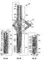
- FIGURES 8A, 8B, and 8C are longitudinal cross-sectional views of a hydraulic embodiment of the invention.
- FIGURES 9A and 9B are longitudinal cross-sectional views of a hydraulic embodiment of the invention in different states of operation.
- FIGURE 10A is a top view of the invention in its fully open state.
- FIGURE 10B is a sectional view of a hydraulic embodiment of the invention in a fully closed state taken along the section line A-A of FIGURE 9A.
- FIGURES 11A through 11E are longitudinal cross-sectional views of a hydraulic embodiment of the invention that schematically show the major operational processes.
- FIGURES 12A, 12B, and 12C are longitudinal cross-sectional views of an electro-mechanical embodiment of the invention that schematically show the major operational processes.
- the present invention proposes an improved passive grip system. It may be used to centralize a logging or other well tool, allow bi-directional motion, and/or have a much wider operational range of well bore sizes than prior art systems.
- the invention is a combination of gripping cams and a centralizer with lockable geometry. It may be used to perform two major functions. The first is to act as a tool centralizer. The second is to selectively grip or release the inside walls of a conduit such as a well or a pipe.
- the invention may be used as a part of a downhole tractor conveyance system. Its major elements may include a grip body, double-sided cams, cam springs, centralizer arms, wheels, hub, centralizer opening/closing device, and/or a locking device.
- the arms and the hub may be combined into linkages that can expand or contract radially as the hub slides with respect to the grip body in the axial direction. These linkages provide extended operational range, centralizing action, and when the hub is locked in place, support for the cams when they grip.
- the centralizer opening/closing device may selectively bias the linkages towards the well walls or close the arms back into the grip body.
- the cams are mounted at the tips of the linkages that come in contact with the well wall.
- the cams may be used to provide the gripping action. Since the cams are double-sided they can be used to grip in both the downhole and uphole directions.
- Cam springs may be provided to keep the cams in contact with the conduit wall.
- the wheels reduce the friction between the arms and the conduit wall when the device does not grip.
- the function of the locking device is to selectively lock or unlock the hub and thus the geometry of the centralizer. All these elements may be mounted onto the grip body.
- the invention may be combined with a linear actuator, rails, a compensator, and an electronics block to form a tractor tool sonde.
- the grip body can slide back and forth on the rails of the sonde.
- One of the linear actuator's functions may be to reciprocate the grip body with respect to the rest of the sonde.
- the compensator provides pressure compensation of internal volumes and the fluid necessary for the operation of the grip.
- the electronics block may drive and control the electric motor of the linear actuator and the locking device.
- Two or more sondes may be used in a complete tractor tool to enable continuous motion of the tractor.
- the tractor tool may contains an electronics cartridge and a logging head that connects the tool to the logging cable. It may also contain additional auxiliary devices.
- the tractor tool may be attached to other logging tools that it can convey along the well.
- the invention may be a part of a downhole tractor conveyance system.
- One possible embodiment of the tractor system in a tool string is schematically shown in FIGURE 1.
- the tool string shown in the figure comprises a logging head 4 that connects the tool string to the logging cable 2, auxiliary equipment 6, electronics cartridge 8, two tractor mechanical sondes 10, and multiple logging tools 12.
- the electronics cartridge 8 and the two mechanical sondes 10 comprise the downhole tractor conveyance system.
- the electronics cartridge 8 is responsible for communication with surface equipment and other tools in the tool string, supply of power to the logging tools, and control of the mechanical sondes 10.
- the elements of the tractor system are not connected to each other and may have logging tools 12 between them as shown in FIGURE 1.
- the grip which is denoted with the reference number 20, may be a part of a mechanical sonde 10.
- Other elements of the mechanical sonde can include an electronics section 14, linear actuator section 16, rail section 18, compensator section 22, and lower head 24.
- the grip 20 slides back and forth inside the rail section 18 and is connected to the linear actuator section 16 and compensator section 22 through push rods 26 and 28.
- the grip 20 and the linear actuator 16, rail 18, and compensator 22 sections are oil-filled, while the electronics section 14 and the lower head 24 are typically air-filled. Bulkheads 30 and 48 separate the oil and air-filled sections of the tool and provide electrical communications between these sections.
- the role of the linear actuator 16 is to reciprocate the grip 20 along the rails 18.
- the major elements of the linear actuator 16 are a motor 32, a gearbox 34, a ball screw 36, and a ball nut 38.
- the ball nut 38 is attached to push rod 26.
- the motor 32 is the prime source of mechanical power for the tool.
- the power and control circuits for the motor can be located in the electronics section 14.
- the ball screw 36 and the ball nut 38 convert the rotary motion at the output shaft of the gearbox 34 into linear motion.
- the push rod 26 also contains a cocking piston 42, which acts as a source of high pressure when activating the grip 20.
- a compensator-side push rod 28 is mainly responsible for electrical and hydraulic communications between the grip 20 and the rest of the tool. This is schematically shown by the wire 44. Note that the grip 20 is exposed to well bore fluid. The push rods 26 and 28 have to repeatedly exit the oil-filled sections of the tool, get into the well bore fluids and then reenter the tool. Dynamic seals 40 and 46 prevent any entry of well fluids into the tool.
- the function of the compensator 22 is to provide pressure compensation, and hydraulic fluid necessary for the operation of the grip 20.
- the compensator 22 is piston-type, which major elements are a piston 50, spring 52 and dynamic seals 54. Except for the grip 20, all other elements of the mechanical sonde have been previously disclosed and are commercially available in embodiments similar to those shown in FIGURE 1. These devices are discussed here because their presence is helpful in explaining the operation of the invention.
- the invention comprises a grip body, double-sided cams, wheels, biasing springs, centralizer linkages, a hub, a centralizer opening/closing device and a locking device.
- FIGURE 2 A three dimensional view of the one possible embodiment of the invention is shown in FIGURE 2 where the grip body is denoted by the reference number 60.
- Three sets of linkages 62 are attached to the grip body 60 and to a hub 64, which can slide with respect to the grip body 60.
- the grip body 60 is attached to the other parts of the tool (not shown) with push rods 26 and 28.
- a magnified view of one of the linkages 62 is shown in FIGURE 3.
- the linkages 62 are comprised of a first arm 66, a second arm 67, and pins 68, which attach the first arm 66 and the second arm 67 to the grip body 60 and to the hub 64.
- the cams 70 and the wheels 72 are mounted on a common axle 74, which also joins the two arms 66.
- One possible arrangement of the elements that are located at the tip of the linkage 62 is shown in FIGURE 4.
- the wheels 72 can rotate freely on the axle 74.
- the cams 70 also can rotate on the axle 74 but are oriented in an outward pointing direction by biasing springs (not shown in the figure) located in slots 76 cut in the arms 66.
- the wheels 72 and the cams 70 are separated by spacers 78, which prevent direct frictional interaction between the wheels 72 and the cams 70.
- the axle 74 is secured in place by a retaining ring 79.
- the shape of the cams 70 is an important feature of the invention. The shape is used to provide both gripping action and bi-directionality.
- a bi-directional gripping cam is shown in FIGURES 5A, 5B, and 5C.
- FIGURE 5A is a front view
- FIGURE 5B represents a three-dimensional view of the cam.
- the geometry of the cam is characterized by a constant contact angle, designated by the letter ⁇ in FIGURES 5A and 5C.
- the contact angle is defined as the angle between a line connecting the center of the cam pivot with the point of contact between the cam surface and a tangential plane, and the normal to that plane that passes through the cam axle.
- FIGURES 6A, 6B, and 6C The interaction of the cam 70 and the wheels 72 with the well wall is explained in FIGURES 6A, 6B, and 6C.
- FIGURE 6B represents a static contact between the cam/wheel system and the well wall 150. The contact is described as static because no axial forces (parallel to the well centerline) are applied to the axle 74.
- a radial centralizing force F C 152 is applied to the axle 74 by a centralizing device, which is not shown in the figure and which is discussed in detail later.
- a much smaller force F S 154 is applied to the cam surface, which is the resultant of the action of two cam springs (not shown in the figure).
- the function of the cam springs is to keep cam 70 in constant contact with the well wall 150.
- the centralizing force F C gives rise to a reaction force F N 156 in the point of contact between the wheel 72 and the wall 150.
- the cam 70 also contacts the wall 150 but in a different contact point. As explained in FIGURE 5A, this contact point is always at an angle ⁇ from the normal direction.
- the force at the point where the cam 70 contacts the wall is denoted by F RS 158. Note that this force is much smaller than F C 152 because force F S exerted by the cam spring is much weaker than the force F C exerted by the centralizing device.
- the wheel 72 carries the majority of the radial load.
- FIGURE 6A Application of an axial force F P 166 in the opposite direction (pointing to the left) is shown in FIGURE 6A.
- the friction force which in FIGURE 6C tended to rotate the cam 70 in the clockwise direction and, thus, away from the wall 150, now forces the cam to rotate in the counterclockwise direction, as indicated by the arrow 172.
- the geometry of the cam 70 is such (see FIGURE 5) that when it rotates on its axle, its contact radius (defined as the distance between the contact point and the axis of the cam axle) either increases or decreases. In this case it increases.
- the cam 70 rotates, it becomes wedged against the well wall 150 by the frictional force F FP 176 at the contact point.
- FIGURES 7A through 7H show the reversal of the cam 70, which then allows change in the direction of tractoring.
- the cam reversal process is similar to the process of gripping the casing that was explained with regards to FIGURE 6A. However, in this case, the vertical displacement of axle 74 is not constrained. In the position of the cam/wheel system shown in FIGURE 7A, the system can move freely to the left and grip if forced to the right. In its initial stage, the cam reversal process follows the events explained in FIGURE 6A.
- An axial force F R 160 is applied to the cam axle 74.
- a reaction friction force ⁇ F RS 162 is then generated by the tendency of the cam 70 to slide with respect to the well wall 150.
- FIGURE 7C shows the rotation of cam 70.
- FIGURE 7E shows the moment just after flipping the cam beyond its largest radius. Note that the axial force has dropped substantially in value and is again indicated by F R 160. From this point on forces F C , F N , and F R all act to continue the rotation of the cam, which for this reason proceeds very quickly. Consecutive positions of the cam are shown in FIGURES 7F and 7G.
- FIGURE 7H is exactly the same as that shown in FIGURE 6C.
- the cam/wheel assembly moves with very little resistance with respect to the well wall 150, as explained with respect to FIGURE 6C.
- the cam/wheel system now moves freely to the right and grips when an attempt is made to move it to the left as long as the radial position of the axle 74 is locked or fixed. This is exactly the opposite of the position shown in FIGURE 7A.
- the reversal of the cam 70 has the effect of changing the direction of tractoring.
- the grip (20 in FIG 1) also includes a centralizer opening/closing device and a locking device.
- a centralizer opening/closing device and a locking device.
- these devices including but not limited to a fully hydraulic system, an electromechanical system, and combinations of these systems.
- the embodiment of a fully hydraulic system for the centralizer opening/closing device and the locking device is presented in detail in FIGURES 8 - 11.
- the embodiment of an electromechanical system is schematically presented in FIGURE 12.
- FIGURE 8A The top portion of the hydraulic embodiment of the grip is shown in FIGURE 8A.
- FIGURE 8B is a continuation of FIGURE 8A
- FIGURE 8C is a continuation of FIGURE 8B.
- the grip body 60 is connected to other parts of the tractor tool (not shown in FIGURE 8) through push rods 26 on the top and 28 on the bottom. As explained earlier, the push rods are used to reciprocate the grip in the rail section (18 in FIGURE 1) and to provide electrical and hydraulic communications.
- the embodiment of the grip shown in FIGURE 8 can be subdivided into several major sections depending on their functionality. These major sections from top to bottom are drive rod attachment 80, opening/closing hydraulic block 90, high pressure accumulator 100, linkages section 110, grip actuator 120, locking hydraulic block 130, and compensator rod attachment 140. These elements are discussed in more detail below.
- the drive section attachment consists of a split clamp 83 and an end cap 82, which is attached to the grip body 60 with bolts 84.
- Passage 81 in the push rod 26 is used for fluid communication between the grip and a cocking piston (not shown in FIGURE 8), which will be explained later.
- Static seals 85 are used to seal off external well fluids from the internal volumes of the tool.
- the invention also includes several identical fill ports 86, which are used for initial filling of the tool with oil, for pressure measurements, and inspection.
- the opening/closing hydraulic block 90 includes a hydraulic block body 96, a solenoid valve 92, check valves 98 and a contact assembly 94.
- the latter is used to supply electrical power to the solenoid valve 92, which can be selectively opened or closed by the control circuits located in the electronics block (14 in FIGURE 1).
- the function of the check valves 98 is to direct the fluid flow in the proper chamber of the grip. A more detailed description of the role of the various hydraulic components is provided later with respect to FIGURE 11.
- the third major section presented in FIGURE 8 is the high-pressure accumulator 100. It is located inside chamber 108 of grip body 60.
- the major elements of the high-pressure accumulator are a floating piston 103 and a spring 106.
- High-pressure dynamic seals 102 mounted on the piston 103 separate the high- pressure region 101 on the top of the piston from the low-pressure region 105 at the bottom.
- a pressure relief valve 104 is mounted inside the piston 103. The role of the valve 104 is to set the maximum pressure of the high-pressure accumulator 100.
- the next section of the grip is the linkages section 110.
- this section houses three identical linkages 62 (described earlier in FIGURES 3 -6) as well as the centralizer hub 64.
- the linkages section 110 may have 2, 4, 5, or 6 linkages.
- the hub 64 is connected to the piston rod 118 with a bolt 116, ensuring that the motion of the piston rod 118 is transmitted to the hub 64.
- Other elements of this section are the auxiliary wheels 112 that pivot on hubs 114. These wheels 112 are used to assist the opening of the arms in small-diameter well bore sizes.
- Features of the grip body 60 in this section include special cuts 115 and slots 117 that provide space for the linkages when the grip is fully closed.
- FIGURE 8 The closing of the linkages 62 into the grip body 60 can be better understood by examining FIGURE 9, which will be discussed later. Also shown in FIGURE 8 are internal passages 107, which are used for hydraulic communication, as well as for passage of electrical wires. The hydraulic connections are discussed in more detail in
- the function of the grip actuator 120 is to force the hub 64 to slide with respect to the grip body 60, thus, opening or closing linkages 62 into the grip body 60.
- Another function of the actuator 120 is to react the large axial forces that may be created by the cams 70 and then transmitted through the linkages 62 and the hub 64 to the actuator rod 118.
- the actuator 120 is similar to a single-acting hydraulic cylinder. It consists of a piston 125 that is attached to the actuator rod 118. The piston 125 slides inside bore 128 in the grip body 60. The piston 125 separates the cylinder chamber 128 into a low-pressure region 124 on top of the piston 125 and a high-pressure region 127 at the bottom.
- High- pressure dynamic seals 126 prevent fluid communication between the low 124 and high 127 pressure regions.
- dynamic seals 122 mounted in a seal cartridge 121 seal around the surface of the actuator rod 118 and prevent external fluid from entering the cylinder chamber 128.
- the piston 125 is pushed upward. This motion is transmitted through the actuator rod 118 to the hub 64, which, in turn, drives linkages 62 out of the grip body 60.
- spring 123 pushes piston 125 downward, resulting in closing linkages 62 into the grip body 60.
- the pressure in the actuator 120 is controlled by the locking hydraulic block 130. Its function is to open or close the ports that connect chamber 128 to the rest of the grip. When these ports are closed, the fluid volume inside the actuator 120 is trapped. Since this fluid is practically incompressible (in one embodiment, oil), the effect of trapping the fluid is to lock the hub 64 in place and, thus, the geometry of linkages 62.
- the locking hydraulic block 130 consists of a body 132, solenoid valve 134 and a contact assembly 136 that provides electric power to the solenoid valve. The contact assembly is connected to other electrical contacts 141 with the wire 138, which runs along a hole 139 in the grip body 60.
- the last major section of the grip is the compensator-side push rod attachment 140, which joins the push rod 28 to the grip body 60.
- This attachment is very similar to the drive rod attachment 80. It consists of a clamp 143 and an end cap 144 that is bolted to the grip body 60 with screws 145.
- the attachment 140 also has static seals 142 that isolate the internal volumes of the grip from external fluids.
- the compensator-side push rod attachment 140 also provides oil communication with the tractor tool low-pressure compensator (24 in FIGURE 1) through an internal channel 148.
- the major difference between rod attachments 80 and 140 is the presence of electrical contacts 142 in attachment 140. These contacts are used to supply power to solenoid valves 92 and 134. These contacts are also connected with the electronics block (14 in FIGURE 1) by wires 146 that run in the channel 148.
- linkages 62 are shown in a fully open position. This corresponds to the topmost position of the hub 64 and the piston 125.
- linkages 62 can fold completely into the grip body 60.
- Linkages 62 are also capable of assuming any intermediate position between their fully open and fully closed states. This is demonstrated in FIGURES 9A and 9B.
- FIGURE 9A shows the same elements of the grip that were described in FIGURE 7B with linkages 62 in the fully closed position.
- FIGURE 9B shows linkages 62 in an intermediate position.
- FIGURE 9A the arms 66 are completely retracted into the grip body cuts 115. Even the cams 70 are retracted below the outline of the grip body 60.
- the hub 64 is in contact with the seal cartridge 121 and the actuator rod 118 is completely inside the cylinder chamber 128.
- the actuator rod is extended upward by the distance denoted by "STROKE" in FIGURE 9B.
- the hub 64 has moved the same distance. This has forced linkages 62 to move out of cuts 115 in the grip body 60 and to expand outwardly in the radial direction. Further upward movement of the actuator rod 118 will cause the linkages 62 to extend even further out. This process of outward expansion can continue until the rod 118 exhausts its stroke or the spring 123 is compressed solid.
- FIGURE 10A represents a top view of the grip in its fully open state.
- FIGURE 10B shows a cross section through the middle of the grip (denoted by 10B-10B in FIGURE 9A) when it is fully closed.
- Figure 10A shows that the grip's radial dimensions can reach several times the envelope of the grip body 60.
- FIGURE 10A also presents a different view for the elements of the linkages 62 that were explained in FIGURES 3 and 4. Also note the three-lobe shape of the grip body 60.
- FIGURE 10B also shows how the cams 70, wheels 72, axles 74, and the other elements located at the tips of the linkages 62 fit inside the grip body 60. Note that when the linkages are fully closed the cams 70 meet at the centerline of the grip body 60.
- the cross section in FIGURE 10B also shows three of the oil and wire communication passages 107 that are machined into the grip body 60.
- FIGURES 11A through 11C This figure shows a simplified representation of the embodiment of the invention. The simplification is done for the sake of clarity when explaining the principle of operation.
- FIGURE 11 only one of the linkages 62 is shown because all linkages operate in a substantially identical manner.
- FIGURES 11A through 11C also depict the hydraulic communications between different sections of the grip.
- the numerical notations used in FIGURES 11A through 11C are the same as those in the figures explained earlier.
- FIGURE 11A shows the invention in its initial non-powered state. In this state, linkages 62 are fully closed into the grip body 60. This state corresponds to the cross sectional view of the grip shown in FIGURE 10B. If the tractor tool is located in a horizontal section of a well, and if the grip is closed, the tractor tool body lies at the bottom of the well bore. Note that in FIGURE 11A both solenoid valves 92 and 134 are not powered and open. Solenoid valve 134 allows hydraulic communication between chambers 101 of the high-pressure accumulator (100 in FIGURE 8B) and 128 of the grip actuator (120 in FIGURE 8B).
- the other solenoid valve 92 and check valves 95, 97, 98, and 99 allow communication between chamber 101, the cocking piston chamber 180 and through push rod 28 the compensating section of the tool (22 in FIGURE 1).
- all internal volumes of the grip are at the same pressure, which is equal to the pressure generated by the tractor tool compensator (22 in FIGURE 1).
- piston 102 is kept in its topmost position by spring 106 and piston 125 is pushed down by spring 123.
- the hub 64 is also all the way down and the actuator rod 118 is fully retracted into the grip body 60.
- spring 123 exerts closing force on linkages 62 and keeps them retracted into the grip body 60.
- the linkages 62 do not extend beyond the outlines of the grip body 60, which corresponds to the situation shown in FIGURE 9A.
- FIGURE 11B demonstrates one function of the grip, which is to centralize the tractor tool in the well bore. This centralization is achieved by pushing linkages 62 out of the grip body in the radial direction until they lift the tool off the well wall and position it at the center of the bore. This process begins by powering solenoid valve 92, which is indicated by arrow 186. Next, the grip (20 in Figure 1) is pulled up by the linear actuator section (16 in FIGURE 1). Initially, cocking piston 42 travels with the grip and is kept in its topmost position by cocking spring 182. As the grip moves upwards, cocking piston 42 comes in contact with the end of the ball screw 36, which prevents further upward motion of piston 42.
- the gripping function of the grip 20 is shown n figure 11D.
- the drive rod exerts a pull force FP 166 in the upward direction, which is opposite to the direction of F R 160 in FIGURE 11C.
- the solenoid valve 134 is now energized and closed, which is indicated by the arrow 194. By closing solenoid valve 134, the only passage out of chamber 128 is blocked and the fluid inside chamber 128 becomes trapped. Due to force F P 166, there is a tendency of the grip 20 to move upwards. This creates a friction force at the interface of the cam 70 and the well wall 150, which tends to rotate the cam 70 in such a way as to enlarge the distance between the wall 150 and axle 74. This process is the same as that described in FIGURE 6A.
- axle 74 moves to the right requires that hub 64 moves down. However, the movement of hub 64 and hence piston 125 downward is prevented by the fluid that is trapped in chamber 128. This makes the geometry of linkage 62 rigid, and prevents any further motion of axle 74. As explained in FIGURE 6A these are the conditions that cause the cam 70 to grip the well wall 150 and to become anchored in place. Since cams 70 and, therefore, grip 20 cannot move with respect to the well wall, the whole tool is pulled with respect to the anchored grip by force F P 166. Anchored grip 20 and pulling of the whole tool with respect to the grip 20 are the events characteristic of the power stroke of the tool.
- FIGURE 11E describes the closing of linkages 62 back into the grip body 60 when power to solenoid valves 92 and 134 is shut off.
- both solenoid valves become open and fluid can flow freely through them.
- Spring 123 pushes piston 125 down, which results in closing linkages 62 into the grip body 60.
- the fluid from chamber 128 flows through solenoid valve 134 and then through passage 129 to chamber 101.
- the fluid could not escape from chamber 101 because solenoid valve 92 was closed.
- solenoid valve 92 is open and the fluid from chamber 101 is pushed through it by spring 106.
- the fluid passes through check valves 98 and 99 to the cocking piston chamber 180 and through passage 107 and rod 28 to the compensator (22in FIGURE1).
- the grip returns back to the position shown in FIGURE 11A.
- FIGURES 8-11 is only one possible construction of centralizing and locking devices.
- Another embodiment uses electromechanical devices as shown schematically in FIGURES 12A through 12C.
- One of the major elements of the electromechanical centralizing and locking devices is ball screw 200, which is supported by bearings 202 and 218 in the grip body 60.
- the ball screw 200 is powered by an electric motor 222.
- a first ball nut 210 and second ball nut 214 travel on the ball screw 200.
- the first ball nut 210 travels with hub 64.
- the first ball nut 210 can rotate with respect to the hub on bearings 208.
- the second ball nut 214 is attached to the carrier 216, which prevents rotation, but allows axial displacement with respect to the grip body 60.
- Brake 206 selectively locks ball nut 210 with respect to hub 64.
- Brake 220 locks the ball screw 200 with respect to the grip body 60.
- Spring 204 is the closing spring and its action is similar to spring 123 in FIGURE 8.
- Spring 212 provides the flexibility necessary for the centralization function of the invention and is functionally equivalent to spring 106 in FIGURE 8.
- FIGURE 12A shows the grip 20 in its non-powered state.
- the grip body 60 is in contact with the well wall 150.
- Both hub 64 and ball nut 214 are pushed all the way down by springs 204 and 212.
- FIGURE 12 A is functionally the same as FIGURE 11 A.
- FIGURE 12 B shows the centralizing action of the grip 20.
- the centralizing action begins by powering motor 222, which turns ball screw 200.
- Ball nut 214 is forced to travel upward until it reaches the position designated by "OPENING STROKE" 224 in FIGURE 12.
- the motor 222 is turned off and brake 220 is activated.
- Brake 220 prevents ball screw 200 from rotating and, hence, keeps ball nut 214 in a fixed position.
- FIGURE 11B This action is equivalent to the action of the cocking piston in FIGURE 11B.
- brake 220 performs the same function as solenoid valve 94 in FIGURE 11B.
- FIGURES 12B and 12C demonstrate the capability of the invention to accommodate changes in the well bore diameter. This is possible through the action of spring 212, which either pushes hub 64 up in order to force linkages 64 further out or takes up the extra stroke when the grip goes through restrictions. In FIGURE 12, this is shown by the difference in displacements ⁇ S, designated by numbers 226 and 228.
- the other major function of the grip the capability to grip the well wall is provided by linkages 62 and by the capability of the grip to lock the position of hub 64 with respect to the grip body 60; the locking is achieved by brake 206.
- brake 206 prevents the rotation of ball nut 210 with respect to the ball screw 200. Since ball screw 200 cannot rotate due to the action of brake 220, the prevention of the rotation of ball nut 210 with respect to ball screw 200 is equivalent to locking the position of hub 64.
- the gripping action of the cams is the same as that described in FIGURES 6A, 6B, and 6C.
- the linear actuator (16 in FIGURE 1) is activated. It starts reciprocating the grip with respect to the sonde body. If the tool has to tractor in the downhole direction, the radial position of the linkages 62 is kept unlocked during the downward stroke of the linear actuator and is locked during the upward stroke. During the downward stroke, the cams automatically orient themselves (see FIGURE 7) in such a way that they can slide freely downhole and grip if an attempt is made to move them uphole. Thus, during the downward stroke the grip is easily pushed downhole by the linear actuator.
- the linkages 62 form a rigid body that keeps the axles of cams at fixed radial positions.
- the attempt to move the grip uphole creates frictional forces between the cam surfaces and the well wall. These forces tend to rotate the cams on their axles. Since the axles' positions are fixed, the tendency of the cams to rotate creates very strong radial forces on the axles. These forces are passively reacted by the centralizer linkages and by the locking device. The high radial forces create sufficient frictional interaction between the grip and the well wall to anchor the grip in place.
- the grip is anchored to the well wall and the linear actuator pulls the rest of the tool with respect to the grip in the downward direction.
- the radial position of the linkages 62 is unlocked and the grip releases the well wall.
- the grip is free to be moved further downhole during the second downward stroke.
- the sequence of locking the the radial position of the linkages 62 during the upward stroke and unlocking it during the downward stroke is repeated, which results in an "inchworm-like" downward motion of the tractor tool.
- the linear actuators of the two sondes moving in opposite directions, it is possible to convert the inchworm motion of each individual sonde into a continuous motion for the whole tool.
- the tractoring is achieved by a "ratchet" action of the tractor.
- the grip In the downward stroke, the grip is unlocked and moves downhole, while the rest of the device is stationary.
- In the upward stroke the grip is locked and stationary relative to the hole, while the rest of the device is pulled downhole with the grip acting as an anchor to the hole wall.
- the same two strokes are combined to produce the motion.
- the grip is locked and anchors to the hole wall, while the rest of the device moves uphole.
- the grip is unlocked and moves uphole, while the rest of the device remains stationary.
- a first embodiment there are two grips operating simultaneously in opposite cycles that allows one grip to always be anchored to the wall while the other grip is moving which allows for a simulated continuous movement of the device.
- one grip is provided that moves, and a secondary stationary grip is also provided.
- the stationary grip is engaged to hold the device stationary relative to the wall of the hole.
- the movable grip reaches the top of its stroke, the movable grip is anchored to the hole and the stationary grip is released so that the device can be pulled up or down the hole while the grip remains stationary. This provides a "inchworm-like" motion.
- the linkages can be closed back into the grip body by the closing device.
Applications Claiming Priority (2)
| Application Number | Priority Date | Filing Date | Title |
|---|---|---|---|
| US09/921,825 US6629568B2 (en) | 2001-08-03 | 2001-08-03 | Bi-directional grip mechanism for a wide range of bore sizes |
| US921825 | 2001-08-03 |
Publications (2)
| Publication Number | Publication Date |
|---|---|
| EP1281834A1 true EP1281834A1 (de) | 2003-02-05 |
| EP1281834B1 EP1281834B1 (de) | 2006-03-22 |
Family
ID=25446026
Family Applications (1)
| Application Number | Title | Priority Date | Filing Date |
|---|---|---|---|
| EP02255222A Expired - Fee Related EP1281834B1 (de) | 2001-08-03 | 2002-07-26 | Bidirektionaler Befestigungsmechanismus für eine grosse Anzahl von Bohrlochgrössen |
Country Status (7)
| Country | Link |
|---|---|
| US (1) | US6629568B2 (de) |
| EP (1) | EP1281834B1 (de) |
| AU (1) | AU2002300367B2 (de) |
| CA (1) | CA2396822C (de) |
| DE (1) | DE60210017T2 (de) |
| NO (1) | NO322981B1 (de) |
| SA (1) | SA02230231B1 (de) |
Cited By (14)
| Publication number | Priority date | Publication date | Assignee | Title |
|---|---|---|---|---|
| WO2005090739A1 (en) * | 2004-03-17 | 2005-09-29 | Western Well Tool, Inc. | Roller link toggle gripper for downhole tractor |
| EP2290190A1 (de) * | 2009-08-31 | 2011-03-02 | Services Petroliers Schlumberger | Verfahren und Vorrichtung für gesteuerte bidirektionale Bewegungen eines Ölfeldwerkzeugs in einer Bohrlochumgebung |
| EP2505764A1 (de) * | 2011-03-30 | 2012-10-03 | Welltec A/S | Bohrlochantriebseinheit mit Federelement zum Anordnen eines Hydraulikmotorgehäuses |
| US8365822B2 (en) | 2009-08-31 | 2013-02-05 | Schlumberger Technology Corporation | Interleaved arm system for logging a wellbore and method for using same |
| US8464791B2 (en) | 2010-08-30 | 2013-06-18 | Schlumberger Technology Corporation | Arm system for logging a wellbore and method for using same |
| US8468882B2 (en) | 2010-11-30 | 2013-06-25 | Schlumberger Technology Corporation | Method and apparatus for logging a wellbore |
| US8485253B2 (en) | 2010-08-30 | 2013-07-16 | Schlumberger Technology Corporation | Anti-locking device for use with an arm system for logging a wellbore and method for using same |
| WO2015112353A1 (en) * | 2014-01-27 | 2015-07-30 | Wwt North America Holdings, Inc. | Eccentric linkage gripper |
| US9988868B2 (en) | 2000-05-18 | 2018-06-05 | Wwt North America Holdings, Inc. | Gripper assembly for downhole tools |
| CN108798552A (zh) * | 2018-06-06 | 2018-11-13 | 黑龙江兰德超声科技股份有限公司 | 一种滑轮式阵列感应扶正器 |
| US10370915B2 (en) | 2014-04-08 | 2019-08-06 | Koto Holdings Limited | Gauge hanger |
| EP3833847A4 (de) * | 2018-08-06 | 2022-04-06 | Services Pétroliers Schlumberger | Systeme und verfahren zur manipulation von bohrlochabschlussprodukten |
| US11391094B2 (en) * | 2014-06-17 | 2022-07-19 | Petrojet Canada Inc. | Hydraulic drilling systems and methods |
| US11442193B2 (en) | 2019-05-17 | 2022-09-13 | Halliburton Energy Services, Inc. | Passive arm for bi-directional well logging instrument |
Families Citing this family (76)
| Publication number | Priority date | Publication date | Assignee | Title |
|---|---|---|---|---|
| BR9610373A (pt) * | 1995-08-22 | 1999-12-21 | Western Well Toll Inc | Ferramenta de furo de tração-empuxo |
| US6651747B2 (en) * | 1999-07-07 | 2003-11-25 | Schlumberger Technology Corporation | Downhole anchoring tools conveyed by non-rigid carriers |
| GB2361488B (en) * | 2000-04-20 | 2004-05-26 | Sondex Ltd | Roller centralizer for wireline tools |
| US6935423B2 (en) * | 2000-05-02 | 2005-08-30 | Halliburton Energy Services, Inc. | Borehole retention device |
| GB0012769D0 (en) * | 2000-05-26 | 2000-07-19 | Weatherford Lamb | Restraint mechanism |
| GB2364079B (en) * | 2000-06-28 | 2004-11-17 | Renovus Ltd | Drill bits |
| US7090025B2 (en) | 2000-10-25 | 2006-08-15 | Weatherford/Lamb, Inc. | Methods and apparatus for reforming and expanding tubulars in a wellbore |
| US7121351B2 (en) * | 2000-10-25 | 2006-10-17 | Weatherford/Lamb, Inc. | Apparatus and method for completing a wellbore |
| US8245796B2 (en) * | 2000-12-01 | 2012-08-21 | Wwt International, Inc. | Tractor with improved valve system |
| US7121364B2 (en) * | 2003-02-10 | 2006-10-17 | Western Well Tool, Inc. | Tractor with improved valve system |
| GB0102021D0 (en) * | 2001-01-26 | 2001-03-14 | E2 Tech Ltd | Apparatus |
| US6920936B2 (en) * | 2002-03-13 | 2005-07-26 | Schlumberger Technology Corporation | Constant force actuator |
| US6796380B2 (en) * | 2002-08-19 | 2004-09-28 | Baker Hughes Incorporated | High expansion anchor system |
| GB0220933D0 (en) * | 2002-09-10 | 2002-10-23 | Weatherford Lamb | Tubing expansion tool |
| US7048089B2 (en) * | 2003-05-07 | 2006-05-23 | Battelle Energy Alliance, Llc | Methods and apparatus for use in detecting seismic waves in a borehole |
| US7156192B2 (en) * | 2003-07-16 | 2007-01-02 | Schlumberger Technology Corp. | Open hole tractor with tracks |
| US7348892B2 (en) * | 2004-01-20 | 2008-03-25 | Halliburton Energy Services, Inc. | Pipe mounted telemetry receiver |
| US7505063B1 (en) * | 2004-02-17 | 2009-03-17 | Ronald A. Basterdo | Self-adjusting and centering camera mount for inspecting pipe |
| US7104318B2 (en) * | 2004-04-07 | 2006-09-12 | Plexus Ocean Systems, Ltd. | Self-contained centralizer system |
| US9500058B2 (en) * | 2004-05-28 | 2016-11-22 | Schlumberger Technology Corporation | Coiled tubing tractor assembly |
| US7617873B2 (en) | 2004-05-28 | 2009-11-17 | Schlumberger Technology Corporation | System and methods using fiber optics in coiled tubing |
| US7334642B2 (en) * | 2004-07-15 | 2008-02-26 | Schlumberger Technology Corporation | Constant force actuator |
| CA2555563C (en) | 2005-08-05 | 2009-03-31 | Weatherford/Lamb, Inc. | Apparatus and methods for creation of down hole annular barrier |
| DE602005018367D1 (de) | 2005-08-08 | 2010-01-28 | Schlumberger Technology Bv | Bohrsystem |
| US7516782B2 (en) * | 2006-02-09 | 2009-04-14 | Schlumberger Technology Corporation | Self-anchoring device with force amplification |
| US7624808B2 (en) * | 2006-03-13 | 2009-12-01 | Western Well Tool, Inc. | Expandable ramp gripper |
| US7748476B2 (en) | 2006-11-14 | 2010-07-06 | Wwt International, Inc. | Variable linkage assisted gripper |
| JP4588014B2 (ja) * | 2006-12-08 | 2010-11-24 | 日立Geニュークリア・エナジー株式会社 | 燃料交換機 |
| US9133673B2 (en) | 2007-01-02 | 2015-09-15 | Schlumberger Technology Corporation | Hydraulically driven tandem tractor assembly |
| US7992642B2 (en) * | 2007-05-23 | 2011-08-09 | Schlumberger Technology Corporation | Polished bore receptacle |
| US7770667B2 (en) * | 2007-06-14 | 2010-08-10 | Wwt International, Inc. | Electrically powered tractor |
| GB2454697B (en) | 2007-11-15 | 2011-11-30 | Schlumberger Holdings | Anchoring systems for drilling tools |
| GB2454701B (en) * | 2007-11-15 | 2012-02-29 | Schlumberger Holdings | Methods of drilling with a downhole drilling machine |
| US7757767B2 (en) * | 2008-03-06 | 2010-07-20 | Baker Hughes Incorporated | Through tubing gun lock |
| US8082980B2 (en) * | 2009-01-21 | 2011-12-27 | Schlumberger Technology Corporation | Downhole well access line cutting tool |
| US8245779B2 (en) * | 2009-08-07 | 2012-08-21 | Geodaq, Inc. | Centralizer apparatus |
| US8485278B2 (en) * | 2009-09-29 | 2013-07-16 | Wwt International, Inc. | Methods and apparatuses for inhibiting rotational misalignment of assemblies in expandable well tools |
| US8602115B2 (en) * | 2009-12-01 | 2013-12-10 | Schlumberger Technology Corporation | Grip enhanced tractoring |
| US20110198099A1 (en) * | 2010-02-16 | 2011-08-18 | Zierolf Joseph A | Anchor apparatus and method |
| US9127507B2 (en) * | 2010-12-14 | 2015-09-08 | Schlumberger Technology Corporation | Rotatable wireline tool of enhanced hydraulic drive consistency |
| EP2505768B1 (de) * | 2011-03-30 | 2016-03-30 | Welltec A/S | Ausfallsichere Feder |
| EP2505767A1 (de) * | 2011-03-30 | 2012-10-03 | Welltec A/S | Ausfallsichere Feder |
| EP2505771A1 (de) | 2011-03-30 | 2012-10-03 | Welltec A/S | Armanordnung |
| US10260299B2 (en) * | 2011-08-05 | 2019-04-16 | Coiled Tubing Specialties, Llc | Internal tractor system for downhole tubular body |
| US9447648B2 (en) | 2011-10-28 | 2016-09-20 | Wwt North America Holdings, Inc | High expansion or dual link gripper |
| US8585110B2 (en) | 2011-12-31 | 2013-11-19 | National Oilwell Varco, L.P. | Internal pipe gripping tool |
| JP6080367B2 (ja) * | 2012-02-29 | 2017-02-15 | ケミカルグラウト株式会社 | 孔芯計測装置 |
| BR112016002220A2 (pt) * | 2013-07-24 | 2017-08-01 | Bp America Production Company | centralizadores para invólucros em poços |
| US9624933B2 (en) * | 2013-08-29 | 2017-04-18 | Dresser-Rand Company | Support assembly for a turbomachine |
| WO2015128487A1 (de) * | 2014-02-28 | 2015-09-03 | Leoni Kabel Holding Gmbh | Kabel, insbesondere induktionskabel, verfahren zum verlegen eines solchen kabels und verlegehilfe |
| NO337937B1 (no) * | 2014-08-20 | 2016-07-11 | E Holstad Holding As | Sentreringsanordning og fremgangsmåte for bruk av en sentreringsanordning |
| NO342655B1 (no) | 2014-08-20 | 2018-06-25 | E Holstad Holding As | Apparat for tetting av en boring, et system omfattende apparatet og en fremgangsmåte ved bruk av apparatet |
| US9777572B2 (en) | 2014-11-17 | 2017-10-03 | Baker Hughes Incorporated | Multi-probe reservoir sampling device |
| US10041319B2 (en) | 2015-02-13 | 2018-08-07 | Halliburton Energy Services, Inc. | Downhole apparatus with anchors and failsafe high torque transmission drive |
| US20160298396A1 (en) * | 2015-04-08 | 2016-10-13 | Probe Technology Services, Inc. | Constant force centralizer |
| US10378292B2 (en) | 2015-11-03 | 2019-08-13 | Nabors Lux 2 Sarl | Device to resist rotational forces while drilling a borehole |
| CN105909234A (zh) * | 2016-05-18 | 2016-08-31 | 北京富地勘察测绘有限公司 | 一种井下自动对中探测装置 |
| GB2578551B (en) | 2017-06-20 | 2022-07-13 | Sondex Wireline Ltd | Sensor deployment system and method |
| US10907467B2 (en) | 2017-06-20 | 2021-02-02 | Sondex Wireline Limited | Sensor deployment using a movable arm system and method |
| GB2578256B (en) | 2017-06-20 | 2022-07-27 | Sondex Wireline Ltd | Sensor bracket system and method |
| US10883325B2 (en) | 2017-06-20 | 2021-01-05 | Sondex Wireline Limited | Arm deployment system and method |
| US10927625B2 (en) | 2018-05-10 | 2021-02-23 | Colorado School Of Mines | Downhole tractor for use in a wellbore |
| CA3149301A1 (en) * | 2019-08-01 | 2021-02-04 | Chevron U.S.A. Inc. | Artificial lift systems utilizing high speed centralizers |
| GB201917970D0 (en) | 2019-12-09 | 2020-01-22 | Innovative Drilling Systems Ltd | Downhole traction tool and method of use |
| US11408229B1 (en) | 2020-03-27 | 2022-08-09 | Coiled Tubing Specialties, Llc | Extendible whipstock, and method for increasing the bend radius of a hydraulic jetting hose downhole |
| US11933112B2 (en) * | 2020-06-08 | 2024-03-19 | Geodynamics, Inc. | Hydraulically powered centralizer device for borehole and method |
| WO2022015206A1 (ru) * | 2020-07-13 | 2022-01-20 | Общество с ограниченной ответственностью "Л-Петро" | Устройство и способ доставки приборов в горизонтальные скважины |
| US11624250B1 (en) | 2021-06-04 | 2023-04-11 | Coiled Tubing Specialties, Llc | Apparatus and method for running and retrieving tubing using an electro-mechanical linear actuator driven downhole tractor |
| CN113653453A (zh) * | 2021-08-18 | 2021-11-16 | 中石化石油工程技术服务有限公司 | 牵引器的井下变径环境自适应调节装置及其控制方法 |
| CA3230024A1 (en) | 2021-08-26 | 2023-03-02 | Colorado School Of Mines | System and method for harvesting geothermal energy from a subterranean formation |
| CN113931613B (zh) * | 2021-09-29 | 2023-07-25 | 中国科学院武汉岩土力学研究所 | 一种深钻孔井下推靠定位对中系统及方法 |
| US11965409B2 (en) * | 2022-03-28 | 2024-04-23 | Schlumberger Technology Corporation | Downhole device communication using measured electrical property of supplied power |
| US11649687B1 (en) | 2022-03-29 | 2023-05-16 | James Dawson | High expansion anti-rotation anchor catcher |
| USD1009088S1 (en) * | 2022-05-10 | 2023-12-26 | Kaldera, LLC | Wellbore tool with extendable arms |
| CN117514983B (zh) * | 2024-01-05 | 2024-03-19 | 成都理工大学 | 一种复杂井筒自适应牵引机器人支撑机构及其控制方法 |
| CN117738599A (zh) * | 2024-02-19 | 2024-03-22 | 东营中达石油设备有限公司 | 一种石油开采用套管扶正器 |
Citations (2)
| Publication number | Priority date | Publication date | Assignee | Title |
|---|---|---|---|---|
| US3063372A (en) * | 1960-04-01 | 1962-11-13 | Jet Res Ct Inc | Apparatus for perforating wells |
| US4325438A (en) * | 1980-03-24 | 1982-04-20 | Scientific Drilling Controls | Lengthening drill string containing an instrument |
Family Cites Families (56)
| Publication number | Priority date | Publication date | Assignee | Title |
|---|---|---|---|---|
| US1177984A (en) | 1914-09-30 | 1916-04-04 | Robert W Beene | Cable-feeder. |
| US2742259A (en) | 1953-04-06 | 1956-04-17 | Cormack E Boucher | Conduit tractor |
| US2871946A (en) | 1956-04-20 | 1959-02-03 | Baker Oil Tools Inc | Apparatus for effecting operation of subsurace well bore devices |
| US3405772A (en) | 1966-09-28 | 1968-10-15 | American Coldset Corp | Sampling device |
| US3670566A (en) | 1970-12-10 | 1972-06-20 | Go Intern Inc | Apparatus for attaching a tool to a conduit in a borehole |
| SU481748A1 (ru) | 1972-12-25 | 1975-08-25 | Самоходное шасси дл передвижени внутри трубы | |
| US3827512A (en) | 1973-01-22 | 1974-08-06 | Continental Oil Co | Anchoring and pressuring apparatus for a drill |
| US3862359A (en) | 1973-10-09 | 1975-01-21 | Thiokol Corp | Inflatable inspection instrument |
| US3890905A (en) | 1974-02-01 | 1975-06-24 | Crc Crose Int Inc | Apparatus for driving a device within a pipe |
| US3926267A (en) | 1974-07-31 | 1975-12-16 | Valentin Konstant Svirschevsky | Device for driving holes in the ground |
| GB1516307A (en) | 1974-09-09 | 1978-07-05 | Babcock & Wilcox Ltd | Apparatus for conveying a device for inspecting or performing operations on the interior of a tube |
| US4095655A (en) | 1975-10-14 | 1978-06-20 | Still William L | Earth penetration |
| CH594848A5 (de) | 1976-02-24 | 1978-01-31 | Sigel Gfeller Alwin | |
| US4071086A (en) | 1976-06-22 | 1978-01-31 | Suntech, Inc. | Apparatus for pulling tools into a wellbore |
| US4031750A (en) | 1976-09-02 | 1977-06-28 | Dresser Industries, Inc. | Apparatus for logging inclined earth boreholes |
| US4177734A (en) | 1977-10-03 | 1979-12-11 | Midcon Pipeline Equipment Co. | Drive unit for internal pipe line equipment |
| US4243099A (en) | 1978-05-24 | 1981-01-06 | Schlumberger Technology Corporation | Selectively-controlled well bore apparatus |
| GB2029500B (en) * | 1978-08-29 | 1982-09-22 | Hayward Tyler Ltd | Means for gripping the inside surface of a pipe |
| US4272781A (en) | 1978-09-08 | 1981-06-09 | Tokyo Shibaura Denki Kabushiki Kaisha | Nondestructive examining apparatus |
| US4192380A (en) | 1978-10-02 | 1980-03-11 | Dresser Industries, Inc. | Method and apparatus for logging inclined earth boreholes |
| US4369713A (en) | 1980-10-20 | 1983-01-25 | Transcanada Pipelines Ltd. | Pipeline crawler |
| US4457236A (en) | 1981-02-24 | 1984-07-03 | Akhmadiev Galimzyan M | Pipe internal towing carriage |
| CA1158182A (en) | 1981-02-25 | 1983-12-06 | Eric G. De Buda | Pneumatically operated pipe crawler |
| DE3111814A1 (de) | 1981-03-25 | 1982-10-07 | Kraftwerk Union AG, 4330 Mülheim | Selbstfahrender rohrinnenmanipulator zum fernbedienten transportieren von pruefgeraeten und werkzeugen laengs vorgegebener vorschubbahnen, vorzugsweise fuer kernkraftanlagen |
| ATE34821T1 (de) | 1982-02-02 | 1988-06-15 | Subscan Systems Ltd | Rohrleitungsfahrzeug. |
| US4676310A (en) | 1982-07-12 | 1987-06-30 | Scherbatskoy Serge Alexander | Apparatus for transporting measuring and/or logging equipment in a borehole |
| US4463814A (en) | 1982-11-26 | 1984-08-07 | Advanced Drilling Corporation | Down-hole drilling apparatus |
| US4557327A (en) | 1983-09-12 | 1985-12-10 | J. C. Kinley Company | Roller arm centralizer |
| FR2556478B1 (fr) | 1983-12-09 | 1986-09-05 | Elf Aquitaine | Procede et dispositif de mesures geophysiques dans un puits fore |
| FR2559913B1 (fr) | 1984-02-17 | 1986-05-30 | Elf Aquitaine | Dispositif de mesures geophysiques dans un puits fore |
| US4919223A (en) | 1988-01-15 | 1990-04-24 | Shawn E. Egger | Apparatus for remotely controlled movement through tubular conduit |
| US4862808A (en) | 1988-08-29 | 1989-09-05 | Gas Research Institute | Robotic pipe crawling device |
| US4838170A (en) | 1988-10-17 | 1989-06-13 | Mcdermott International, Inc. | Drive wheel unit |
| US5184676A (en) | 1990-02-26 | 1993-02-09 | Graham Gordon A | Self-propelled apparatus |
| ES2088791T3 (es) | 1990-04-12 | 1996-09-16 | Htc As | Orificio de perforacion asi como metodo y aparato para su realizacion. |
| JP3149110B2 (ja) | 1990-09-28 | 2001-03-26 | 株式会社東芝 | 走行機構及びその走行機構を備えた走行装置 |
| DK292690D0 (da) | 1990-12-10 | 1990-12-10 | Htc As | Motor- eller pumpeaggregat |
| US5293823A (en) | 1992-09-23 | 1994-03-15 | Box W Donald | Robotic vehicle |
| FR2697578B1 (fr) | 1992-11-05 | 1995-02-17 | Schlumberger Services Petrol | Centreur pour sondage. |
| US5433493A (en) * | 1993-03-25 | 1995-07-18 | Lifting Technologies, Inc. | Apparatus for securing a load-carrying implement to a lifting member |
| US5309844A (en) | 1993-05-24 | 1994-05-10 | The United States Of America As Represented By The United States Department Of Energy | Flexible pipe crawling device having articulated two axis coupling |
| US5375530A (en) | 1993-09-20 | 1994-12-27 | The United States Of America As Represented By The Department Of Energy | Pipe crawler with stabilizing midsection |
| NO940493D0 (no) | 1994-02-14 | 1994-02-14 | Norsk Hydro As | Lokomotiv eller traktor for fremtrekking av utstyr i et rör eller borehull |
| US6003606A (en) | 1995-08-22 | 1999-12-21 | Western Well Tool, Inc. | Puller-thruster downhole tool |
| US5765640A (en) * | 1996-03-07 | 1998-06-16 | Baker Hughes Incorporated | Multipurpose tool |
| US5794703A (en) | 1996-07-03 | 1998-08-18 | Ctes, L.C. | Wellbore tractor and method of moving an item through a wellbore |
| GB9617115D0 (en) | 1996-08-15 | 1996-09-25 | Astec Dev Ltd | Pipeline traction system |
| US6112809A (en) | 1996-12-02 | 2000-09-05 | Intelligent Inspection Corporation | Downhole tools with a mobility device |
| US5848479A (en) | 1997-06-18 | 1998-12-15 | Federal Products Co. | Bore gauge centralizer |
| US6179055B1 (en) | 1997-09-05 | 2001-01-30 | Schlumberger Technology Corporation | Conveying a tool along a non-vertical well |
| US5954131A (en) | 1997-09-05 | 1999-09-21 | Schlumberger Technology Corporation | Method and apparatus for conveying a logging tool through an earth formation |
| AR018459A1 (es) | 1998-06-12 | 2001-11-14 | Shell Int Research | Metodo y disposicion para mover equipos hacia y a traves de un conducto y dispositivo de vaiven para ser usado en dicha disposicion |
| US6232773B1 (en) | 1998-09-05 | 2001-05-15 | Bj Services Company | Consistent drag floating backing bar system for pipeline pigs and method for using the same |
| US6347674B1 (en) | 1998-12-18 | 2002-02-19 | Western Well Tool, Inc. | Electrically sequenced tractor |
| GB2351308B (en) | 1998-12-18 | 2003-05-28 | Western Well Tool Inc | Electro-hydraulically controlled tractor |
| US6273189B1 (en) | 1999-02-05 | 2001-08-14 | Halliburton Energy Services, Inc. | Downhole tractor |
-
2001
- 2001-08-03 US US09/921,825 patent/US6629568B2/en not_active Expired - Lifetime
-
2002
- 2002-07-26 DE DE60210017T patent/DE60210017T2/de not_active Expired - Lifetime
- 2002-07-26 EP EP02255222A patent/EP1281834B1/de not_active Expired - Fee Related
- 2002-08-01 AU AU2002300367A patent/AU2002300367B2/en not_active Ceased
- 2002-08-01 NO NO20023658A patent/NO322981B1/no not_active IP Right Cessation
- 2002-08-02 CA CA002396822A patent/CA2396822C/en not_active Expired - Lifetime
- 2002-08-03 SA SA02230231A patent/SA02230231B1/ar unknown
Patent Citations (2)
| Publication number | Priority date | Publication date | Assignee | Title |
|---|---|---|---|---|
| US3063372A (en) * | 1960-04-01 | 1962-11-13 | Jet Res Ct Inc | Apparatus for perforating wells |
| US4325438A (en) * | 1980-03-24 | 1982-04-20 | Scientific Drilling Controls | Lengthening drill string containing an instrument |
Cited By (20)
| Publication number | Priority date | Publication date | Assignee | Title |
|---|---|---|---|---|
| US9988868B2 (en) | 2000-05-18 | 2018-06-05 | Wwt North America Holdings, Inc. | Gripper assembly for downhole tools |
| WO2005090739A1 (en) * | 2004-03-17 | 2005-09-29 | Western Well Tool, Inc. | Roller link toggle gripper for downhole tractor |
| US8579037B2 (en) | 2009-08-31 | 2013-11-12 | Schlumberger Technology Corporation | Method and apparatus for controlled bidirectional movement of an oilfield tool in a wellbore environment |
| EP2290190A1 (de) * | 2009-08-31 | 2011-03-02 | Services Petroliers Schlumberger | Verfahren und Vorrichtung für gesteuerte bidirektionale Bewegungen eines Ölfeldwerkzeugs in einer Bohrlochumgebung |
| US8365822B2 (en) | 2009-08-31 | 2013-02-05 | Schlumberger Technology Corporation | Interleaved arm system for logging a wellbore and method for using same |
| US8464791B2 (en) | 2010-08-30 | 2013-06-18 | Schlumberger Technology Corporation | Arm system for logging a wellbore and method for using same |
| US8485253B2 (en) | 2010-08-30 | 2013-07-16 | Schlumberger Technology Corporation | Anti-locking device for use with an arm system for logging a wellbore and method for using same |
| US8468882B2 (en) | 2010-11-30 | 2013-06-25 | Schlumberger Technology Corporation | Method and apparatus for logging a wellbore |
| US9359844B2 (en) | 2011-03-30 | 2016-06-07 | Welltec A/S | Downhole driving unit having a spring member for assembling a hydraulic motor housing |
| WO2012130938A1 (en) * | 2011-03-30 | 2012-10-04 | Welltec A/S | Downhole driving unit having a spring member for assembling a hydraulic motor housing |
| EP2505764A1 (de) * | 2011-03-30 | 2012-10-03 | Welltec A/S | Bohrlochantriebseinheit mit Federelement zum Anordnen eines Hydraulikmotorgehäuses |
| WO2015112353A1 (en) * | 2014-01-27 | 2015-07-30 | Wwt North America Holdings, Inc. | Eccentric linkage gripper |
| US10156107B2 (en) | 2014-01-27 | 2018-12-18 | Wwt North America Holdings, Inc. | Eccentric linkage gripper |
| US10934793B2 (en) | 2014-01-27 | 2021-03-02 | Wwt North America Holdings, Inc. | Eccentric linkage gripper |
| US11608699B2 (en) | 2014-01-27 | 2023-03-21 | Wwt North America Holdings, Inc. | Eccentric linkage gripper |
| US10370915B2 (en) | 2014-04-08 | 2019-08-06 | Koto Holdings Limited | Gauge hanger |
| US11391094B2 (en) * | 2014-06-17 | 2022-07-19 | Petrojet Canada Inc. | Hydraulic drilling systems and methods |
| CN108798552A (zh) * | 2018-06-06 | 2018-11-13 | 黑龙江兰德超声科技股份有限公司 | 一种滑轮式阵列感应扶正器 |
| EP3833847A4 (de) * | 2018-08-06 | 2022-04-06 | Services Pétroliers Schlumberger | Systeme und verfahren zur manipulation von bohrlochabschlussprodukten |
| US11442193B2 (en) | 2019-05-17 | 2022-09-13 | Halliburton Energy Services, Inc. | Passive arm for bi-directional well logging instrument |
Also Published As
| Publication number | Publication date |
|---|---|
| DE60210017D1 (de) | 2006-05-11 |
| NO20023658D0 (no) | 2002-08-01 |
| EP1281834B1 (de) | 2006-03-22 |
| DE60210017T2 (de) | 2007-02-22 |
| US6629568B2 (en) | 2003-10-07 |
| NO322981B1 (no) | 2006-12-18 |
| US20030024710A1 (en) | 2003-02-06 |
| NO20023658L (no) | 2003-02-04 |
| CA2396822A1 (en) | 2003-02-03 |
| AU2002300367B2 (en) | 2007-05-31 |
| SA02230231B1 (ar) | 2006-10-29 |
| CA2396822C (en) | 2006-06-06 |
Similar Documents
| Publication | Publication Date | Title |
|---|---|---|
| US6629568B2 (en) | Bi-directional grip mechanism for a wide range of bore sizes | |
| US7854258B2 (en) | Self-anchoring device with force amplification | |
| US6464003B2 (en) | Gripper assembly for downhole tractors | |
| US6286592B1 (en) | Puller-thruster downhole tool | |
| US7392859B2 (en) | Roller link toggle gripper and downhole tractor | |
| US5954131A (en) | Method and apparatus for conveying a logging tool through an earth formation | |
| US6715559B2 (en) | Gripper assembly for downhole tractors | |
| CA2230185C (en) | Puller-thruster downhole tool | |
| WO1997008418A9 (en) | Puller-thruster downhole tool | |
| WO2008024925A1 (en) | Wellbore tractor with fluid conduit sheath | |
| GB2340526A (en) | Puller-thruster downhole tool |
Legal Events
| Date | Code | Title | Description |
|---|---|---|---|
| PUAI | Public reference made under article 153(3) epc to a published international application that has entered the european phase |
Free format text: ORIGINAL CODE: 0009012 |
|
| AK | Designated contracting states |
Designated state(s): AT BE BG CH CY CZ DE DK EE ES FI FR GB GR IE IT LI LU MC NL PT SE SK TR |
|
| AX | Request for extension of the european patent |
Extension state: AL LT LV MK RO SI |
|
| 17P | Request for examination filed |
Effective date: 20030407 |
|
| AKX | Designation fees paid |
Designated state(s): DE FR GB NL |
|
| 17Q | First examination report despatched |
Effective date: 20050301 |
|
| GRAP | Despatch of communication of intention to grant a patent |
Free format text: ORIGINAL CODE: EPIDOSNIGR1 |
|
| RIN1 | Information on inventor provided before grant (corrected) |
Inventor name: CORDERA, JOSEPH F. Inventor name: ROY, CARL J. Inventor name: SHEIRETOV, TODOR K. Inventor name: POST, ROGER A. |
|
| GRAS | Grant fee paid |
Free format text: ORIGINAL CODE: EPIDOSNIGR3 |
|
| GRAA | (expected) grant |
Free format text: ORIGINAL CODE: 0009210 |
|
| AK | Designated contracting states |
Kind code of ref document: B1 Designated state(s): DE FR GB NL |
|
| REG | Reference to a national code |
Ref country code: GB Ref legal event code: FG4D |
|
| REF | Corresponds to: |
Ref document number: 60210017 Country of ref document: DE Date of ref document: 20060511 Kind code of ref document: P |
|
| ET | Fr: translation filed | ||
| PLBE | No opposition filed within time limit |
Free format text: ORIGINAL CODE: 0009261 |
|
| STAA | Information on the status of an ep patent application or granted ep patent |
Free format text: STATUS: NO OPPOSITION FILED WITHIN TIME LIMIT |
|
| 26N | No opposition filed |
Effective date: 20061227 |
|
| REG | Reference to a national code |
Ref country code: FR Ref legal event code: PLFP Year of fee payment: 15 |
|
| PGFP | Annual fee paid to national office [announced via postgrant information from national office to epo] |
Ref country code: FR Payment date: 20160613 Year of fee payment: 15 |
|
| PGFP | Annual fee paid to national office [announced via postgrant information from national office to epo] |
Ref country code: NL Payment date: 20160711 Year of fee payment: 15 |
|
| PGFP | Annual fee paid to national office [announced via postgrant information from national office to epo] |
Ref country code: GB Payment date: 20160720 Year of fee payment: 15 Ref country code: DE Payment date: 20160720 Year of fee payment: 15 |
|
| REG | Reference to a national code |
Ref country code: DE Ref legal event code: R119 Ref document number: 60210017 Country of ref document: DE |
|
| REG | Reference to a national code |
Ref country code: NL Ref legal event code: MM Effective date: 20170801 |
|
| GBPC | Gb: european patent ceased through non-payment of renewal fee |
Effective date: 20170726 |
|
| REG | Reference to a national code |
Ref country code: FR Ref legal event code: ST Effective date: 20180330 |
|
| PG25 | Lapsed in a contracting state [announced via postgrant information from national office to epo] |
Ref country code: DE Free format text: LAPSE BECAUSE OF NON-PAYMENT OF DUE FEES Effective date: 20180201 Ref country code: GB Free format text: LAPSE BECAUSE OF NON-PAYMENT OF DUE FEES Effective date: 20170726 Ref country code: NL Free format text: LAPSE BECAUSE OF NON-PAYMENT OF DUE FEES Effective date: 20170801 |
|
| PG25 | Lapsed in a contracting state [announced via postgrant information from national office to epo] |
Ref country code: FR Free format text: LAPSE BECAUSE OF NON-PAYMENT OF DUE FEES Effective date: 20170731 |
|
| P01 | Opt-out of the competence of the unified patent court (upc) registered |
Effective date: 20231208 |