EP2505767A1 - Ausfallsichere Feder - Google Patents
Ausfallsichere Feder Download PDFInfo
- Publication number
- EP2505767A1 EP2505767A1 EP11160492A EP11160492A EP2505767A1 EP 2505767 A1 EP2505767 A1 EP 2505767A1 EP 11160492 A EP11160492 A EP 11160492A EP 11160492 A EP11160492 A EP 11160492A EP 2505767 A1 EP2505767 A1 EP 2505767A1
- Authority
- EP
- European Patent Office
- Prior art keywords
- piston
- downhole tool
- arm
- tool according
- spring
- Prior art date
- Legal status (The legal status is an assumption and is not a legal conclusion. Google has not performed a legal analysis and makes no representation as to the accuracy of the status listed.)
- Withdrawn
Links
- 230000004913 activation Effects 0.000 claims abstract description 45
- 239000012530 fluid Substances 0.000 claims description 29
- 230000000712 assembly Effects 0.000 claims description 17
- 238000000429 assembly Methods 0.000 claims description 17
- 238000012544 monitoring process Methods 0.000 claims description 3
- 230000013011 mating Effects 0.000 claims description 2
- 238000004519 manufacturing process Methods 0.000 description 10
- 238000004873 anchoring Methods 0.000 description 3
- 230000015556 catabolic process Effects 0.000 description 3
- 238000012423 maintenance Methods 0.000 description 2
- 230000007246 mechanism Effects 0.000 description 2
- 230000002378 acidificating effect Effects 0.000 description 1
- 238000004891 communication Methods 0.000 description 1
- 230000006835 compression Effects 0.000 description 1
- 238000007906 compression Methods 0.000 description 1
- 230000006837 decompression Effects 0.000 description 1
- 238000005553 drilling Methods 0.000 description 1
- 238000012986 modification Methods 0.000 description 1
- 230000004048 modification Effects 0.000 description 1
- 230000036316 preload Effects 0.000 description 1
- 238000007789 sealing Methods 0.000 description 1
Images


Classifications
-
- E—FIXED CONSTRUCTIONS
- E21—EARTH DRILLING; MINING
- E21B—EARTH DRILLING, e.g. DEEP DRILLING; OBTAINING OIL, GAS, WATER, SOLUBLE OR MELTABLE MATERIALS OR A SLURRY OF MINERALS FROM WELLS
- E21B23/00—Apparatus for displacing, setting, locking, releasing, or removing tools, packers or the like in the boreholes or wells
- E21B23/14—Apparatus for displacing, setting, locking, releasing, or removing tools, packers or the like in the boreholes or wells for displacing a cable or cable-operated tool, e.g. for logging or perforating operations in deviated wells
-
- E—FIXED CONSTRUCTIONS
- E21—EARTH DRILLING; MINING
- E21B—EARTH DRILLING, e.g. DEEP DRILLING; OBTAINING OIL, GAS, WATER, SOLUBLE OR MELTABLE MATERIALS OR A SLURRY OF MINERALS FROM WELLS
- E21B17/00—Drilling rods or pipes; Flexible drill strings; Kellies; Drill collars; Sucker rods; Cables; Casings; Tubings
- E21B17/10—Wear protectors; Centralising devices, e.g. stabilisers
- E21B17/1014—Flexible or expansible centering means, e.g. with pistons pressing against the wall of the well
- E21B17/1021—Flexible or expansible centering means, e.g. with pistons pressing against the wall of the well with articulated arms or arcuate springs
-
- E—FIXED CONSTRUCTIONS
- E21—EARTH DRILLING; MINING
- E21B—EARTH DRILLING, e.g. DEEP DRILLING; OBTAINING OIL, GAS, WATER, SOLUBLE OR MELTABLE MATERIALS OR A SLURRY OF MINERALS FROM WELLS
- E21B23/00—Apparatus for displacing, setting, locking, releasing, or removing tools, packers or the like in the boreholes or wells
- E21B23/001—Self-propelling systems or apparatus, e.g. for moving tools within the horizontal portion of a borehole
-
- E—FIXED CONSTRUCTIONS
- E21—EARTH DRILLING; MINING
- E21B—EARTH DRILLING, e.g. DEEP DRILLING; OBTAINING OIL, GAS, WATER, SOLUBLE OR MELTABLE MATERIALS OR A SLURRY OF MINERALS FROM WELLS
- E21B23/00—Apparatus for displacing, setting, locking, releasing, or removing tools, packers or the like in the boreholes or wells
- E21B23/04—Apparatus for displacing, setting, locking, releasing, or removing tools, packers or the like in the boreholes or wells operated by fluid means, e.g. actuated by explosion
- E21B23/042—Apparatus for displacing, setting, locking, releasing, or removing tools, packers or the like in the boreholes or wells operated by fluid means, e.g. actuated by explosion using a single piston or multiple mechanically interconnected pistons
Definitions
- the present invention relates to a downhole tool extending in a longitudinal direction, comprising a tool housing; an arm assembly movable between a retracted position and a projecting position in relation to the tool housing; an arm activation assembly for moving the arm assembly between the retracted position and the projecting position; wherein the arm activation assembly comprises: a piston housing comprising a piston chamber, said piston chamber extending in the longitudinal direction of the downhole tool, a piston member arranged inside the piston chamber and engaged with the arm assembly to move the arm assembly between the retracted position and the projecting position, the piston member being movable in the longitudinal direction of the downhole tool and having a first piston face and a second piston face, the piston member being able to apply a projecting force on the arm assembly by applying a hydraulic pressure on the first piston face moving the piston in a first direction, and a spring member applying a spring force on the second piston face in a second direction opposite the first direction.
- Downhole tools are used for operations inside boreholes of oil and gas wells. Downhole tools operate in a very harsh environment and must be able to withstand inter alia corroding fluids, high temperatures and high pressure.
- a tool string may comprise both transportation tools for transporting the tool string in the well and operational tools for performing various operations downhole, e.g. centralising tools for centralising the tool or tool string in the borehole, driving units for moving the tool or tool string in the borehole and anchoring tools for anchoring the tool or tool string in the borehole.
- a downhole tool extending in a longitudinal direction, comprising:
- the arm activation assembly may comprise a fluid channel and the hydraulic pressure may be applied to the first piston face with a pressurised hydraulic fluid such as oil through the fluid channel.
- the spring member may be arranged in a spring chamber and the piston may be arranged in a piston chamber.
- Said piston housing may comprise a recess for receiving part of the shaft when the piston moves.
- the shaft may extend in the piston chamber and into the spring chamber.
- the piston member may divide the piston housing into a first and a second section, the first section being filled with fluid for moving the piston member.
- the downhole tool according to the invention may further comprise a pump for pressurising the pressurised hydraulic fluid for moving the piston in the first direction.
- the downhole tool according to the invention may comprise an electrical motor for driving the pump.
- the downhole tool may be connected with a wireline and the electrical motor may be powered through the wireline.
- the downhole tool may comprise several arm assemblies and arm activation assemblies and each of the arm assemblies may be moved by one of the arm activation assemblies.
- piston chamber and spring chamber may be arranged substantially end-to-end in the longitudinal direction of the tool.
- the downhole tool according to the invention may further comprise a control member arranged inside a coil of the spring.
- the piston may comprise a distal part with a reduced diameter engageable with the spring member.
- Said spring member may be is a coil spring, a helical spring, a bellows, a volute spring, a leaf spring, a gas spring or a disc spring.
- the downhole tool according to the invention may further comprise electrical sensors for monitoring a pressure on the first piston face for producing a feedback signal to a control system.
- the downhole tool according to the invention may comprise electrical sensors for monitoring a position of the piston member for producing a feedback signal to a control system.
- the above-mentioned spring member may be preloaded before being compressed by the piston during application of the hydraulic pressure on the first piston face moving the piston in a first direction.
- the piston member may be connected with the arm assembly using a worm shaft, a crank arm or a rack or a pivot joint or a recess in the piston member.
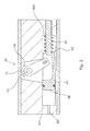
- Fig. 1 shows an arm activation assembly 40 for moving an arm assembly 60 which is shown in Fig. 6 between a retracted position and a projecting position.
- the arm activation assembly 40 is arranged in a tool housing 54 of a downhole tool being part of a tool string 10. An example of such tool string is shown in Fig. 8 .
- the arm activation assembly 40 comprises a piston housing 41, a piston chamber 42 extending in a longitudinal direction of the downhole tool.
- a piston member 47 is arranged inside the piston chamber and the piston member is engaged with the arm assembly. When the piston member 47 is moved back and forth in the longitudinal direction of the piston chamber, the piston member will move a crank arm 72 of an engaging crank 70.
- crank shaft 71 When moving the crank arm 72, a crank shaft 71 is rotated around a rotation axis 32, and hence the arm assembly is moved between a retracted position and a projected position.
- the crank 70 connects the piston member 47 with the arm assembly converting a transverse motion of the piston member to a rotation force acting on the arm assembly.
- the arm assembly may be directly connected with a piston member 47.
- the crank arm is connected with the piston member by the crank arm being arranged in a recess in the piston member and engaging the piston member by engaging means 83.
- the crank arm may however be connected to the piston member in any suitable way known to the person skilled, such as by using a rack also known as a toothed rack or gear-rack, or a worm shaft or a sliding pivot joint.
- the piston member is dividing the piston chamber into a first section 42a and a second section 42b, the first section being in fluid communication with an activation fluid channel 80.
- a hydraulic fluid such as oil may be injected through the fluid channel 80 into the first section 42a of the chamber 42, thereby applying a hydraulic pressure on a first piston face 48 of the piston member 47.
- a spring member 44 is arranged in the second section 42b of the chamber between a second piston face 49 of the piston member and a distal end face 42d of the piston chamber. The spring member 44 applies a spring force to the second piston face 49.
- the hydraulic fluid moves the piston in a first direction and the spring member 44 moves the piston in a second direction opposite the first direction.
- the arm activation assembly in Fig. 1 has the piston member 47 which may comprise a piston part 47a and a piston shaft part 47b.
- the spring member may then circumscribe the piston shaft part, such that the travel of the spring member 44 during compression and decompression is well controlled.
- the piston shaft part may engage a recess 82 in the piston housing 41 to further improve control of the travel of the piston member within the piston chamber. The control of the travel of the piston member is improved since a distal end of the piston shaft part abuts the walls of the recess during travel of the piston.
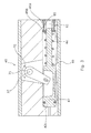
- Fig. 2 shows the arm activation assembly in a projected position.
- a hydraulic pressure is applied to the first piston face 48 of the piston member 47 by pressurising a hydraulic fluid in the first section 42a of the piston chamber 42.
- the hydraulic pressure is applied to the first piston face, the piston member moves towards the distal end face 42d of the piston chamber, thereby compressing the spring member 44.
- the hydraulic pressure must exceed a spring force applied by the spring member 44 on the second piston face 49 and additional frictional forces stemming from the travel of the piston member in the piston chamber.
- crank arm 72 Furthermore, the movement of the piston member results in a movement of the crank arm 72 since the piston member engages the crank arm.
- crank arm When the crank arm is moved in the longitudinal direction of the piston chamber towards the distal end face 42d, the crank shaft 71 will rotate around the rotation axis 32 of the crank 70.
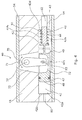
- Fig. 3 shows the arm activation assembly in a retracted position.
- the hydraulic pressure which during projection was applied to a first piston face 48 of the piston member 47 by pressurising a hydraulic fluid in the first section, is then removed.
- the hydraulic pressure will no longer exceed the spring force applied by the spring member on the second piston face, and the piston member will therefore begin to move towards the distal end face 42c of the piston chamber forced by the spring member, thereby decompressing the spring member.
- the spring member acts as a fail-safe so that the tool can always be retracted from the well.
- a downhole tool When working with downhole operations, jamming of downhole tools in a borehole is one of the most aggravating problems, which may cause downtime in the production, and even worse it may shut down a borehole if the jammed downhole tool cannot subsequently be removed. If the hydraulic pressure in the first section is lost, the arm activation assembly 40 will always move to a retracted position due to the spring member 44. Being unable to project the arm assembly with the arm activation assembly is of course inexpedient but it is not critical to the downhole operation since the tool string is merely retracted to the surface by a wireline 9 or a coiled tubing 9 connecting the tool string to the surface (shown in Fig. 8 ). Furthermore, a downhole tool may comprise several arm assemblies and if one does not project others will.
- the arm activation assembly 40 further comprises preloading means 85 for preloading the spring member 44.
- the preloading means allows assembly of the arm activation assembly with an uncompressed spring member 44, where the spring member then, subsequent to the assembly of the arm activation assembly, can be preloaded using the preloading means.
- the preloading means may comprise a screw 85a or a plurality of screws 85a and a washer 85b.
- the preloading means may furthermore allow the user to preload, i.e. compress, the spring member to a certain degree to accommodate for certain requirements to the retraction mechanism of the arm activation assembly.
- a high retraction force may be, if the arm assembly has been used to anchor the tool string in a production casing or the borehole and therefore is sticking to the surface of the production casing or wall of the borehole.
- a lower retraction force may be needed if for example the arm assembly is used for wheels 62 in a driving section 11.
- the retracting force in this situation may not necessarily have to be very high, and a low retraction force exerted by the spring member 44 may be more appropriate for providing a slower retraction of the wheels.
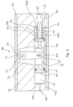
- the spring member is arranged in a spring chamber 42a and the piston is arranged in a piston chamber 42.
- the mounting of springs during production and/or maintenance of separable equipment including springs present a possible risk to the user. Therefore, enclosure of the spring member in a separate chamber may be advantageous to the handling and maintenance of such equipment, especially in a case where a very high preloading force of the spring is required.
- the spring force from the spring member still has to be capable of engaging the piston member in the piston chamber.
- the piston shaft part may enter the spring chamber 42a through a connection hole between the piston chamber and the spring chamber such as shown in Fig. 4 .
- the engagement of the piston member and the spring member may be facilitated by an intermediate piston member 86 sealing off the spring chamber as shown in Fig. 2 .
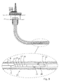
- Fig. 6 is an illustration of a part of the downhole tool with one arm assembly in a projected position and another arm assembly in a retracted position.
- the arm assembly may be used for several purposes during downhole operations such as tool centralising in the borehole 4 or inside a production casing 6, furthermore an arm assembly may be used for anchoring e.g. to ensure weight on bit during horizontal drilling, during downhole stroking or during operations perforating the production casing when setting up production zones.
- the crank shaft may be connected to the arm member 61 by means such as a toothed crank shaft pattern mating with a similar pattern (not shown) in a bore in the arm member.
- the crank shaft and the arm member hereby interlock whereby the rotation force is transferred from the crank shaft to arm member.
- Fig. 7 is another illustration of a part of the downhole tool with one arm assembly in the projected position and another arm assembly in a retracted position.
- the arm assembly comprises an arm member and furthermore a wheel 62 for driving the tool string during downhole operations.
- An arm member 61 of the arm assembly 60 is seen in the left side of Fig. 7 in the projected position and in this situation engaging an inner wall of a production casing 6.
- an elongate axis of the arm member 61 has a projection angle A1 of less than ninety degrees with respect to the longitudinal axis of the tool string. In this way, the retraction of the arm assembly will not have a barbing function when pulling the wireline 9 or coiled tubing 9.
- crank shaft 71 is arranged away from a centre axis of the arm assembly. The intention is to be able to reach as far as possible away from the tool string thereby being able to operate with larger casings.
- the number of driving units 11 and/or the number of wheels 62 in a tool string may be varied depending on the required pulling force e.g. high pulling force is required when operating a heavy tool string. Therefore, a number of arm activation assemblies and arm assemblies may be arranged in a driving unit and/or more than one driving unit may be arranged in the tool string.
- the downhole tool string 10 shown in Fig. 8 comprises an electrical motor 17 for moving a hydraulic pump 18.
- the hydraulic motor 18 may be used to generate a pressurised hydraulic fluid.
- the pressurised fluid may be injected through the fluid channel 80 and into the first section of the chamber to project the arm assembly by means of the arm activation assembly.
- the electric motor 17 may be powered from the surface by a wireline 9 or alternatively the electric motor may be powered by batteries (not shown) arranged in the tool string.
- the hydraulic pump may be replaced by a hydraulic pump at the surface generating a pressurised fluid at the surface which is pumped through a coiled tubing 9 to the downhole tool string.
- Coiled tubing operations are typically limited to smaller depths of boreholes due to the weight of the coiled tubing. At very large depths and in horizontal parts of the well wireline operations are therefore more appropriate than coiled tubing operations.
- the shown tool string comprises a downhole tool in the form of a driving unit 11 for moving the tool string forward downhole.
- the downhole tool extends in a longitudinal direction comprises a tool housing, arm assemblies and arm activation assemblies.
- the tool string shown in Fig. 9 is moved forward by several wheels projecting towards the casing or side walls of the well.
- the wheels are mounted on the arm member 61 such that they can be moved between a retracted position and a projecting position. When the wheels turn the tool string is moved forward deeper into the hole and typically the wireline or the coiled tubing is used to retract the tool string back towards the surface, since it is faster than using downhole propagation means such as the driving unit.
- the fluid transferred into the first section of the chamber may be branched out through other fluid channels to reach an adjacent arm activation assembly (not shown) in a driving unit.
- the arm activation assembly may thus comprise an integrated fluid circuit in the form of fluid channels provided in the walls of the piston housing.
- Several activation assemblies may then be combined to provide a larger fluid circuit without the need of external piping connecting the individual activation assemblies. Fluid channels of subsequent piston houses are joined by connectors (not shown) creating tight fluid joints.
- the spring member 44 may be any type member exerting a spring force on the second piston face 49 such as a coil spring, helical spring, bellow, volute spring, leaf spring, gas spring or disc spring.
- the spring type may be used for designing an appropriate spring force exerted on the piston member such as a constant spring force or a spring force that increases during projection of the arm assembly such that the highest spring force is obtained at the outermost position of the arm assembly.
- switches for determining position of the piston member 47 and/or crank arm 72 feedback signals may be fed back to the user and/or to controlling electronics 16 in the tool string (shown in Fig. 8 ).
Priority Applications (9)
| Application Number | Priority Date | Filing Date | Title |
|---|---|---|---|
| EP11160492A EP2505767A1 (de) | 2011-03-30 | 2011-03-30 | Ausfallsichere Feder |
| PCT/EP2012/055641 WO2012130942A1 (en) | 2011-03-30 | 2012-03-29 | Fail-safe spring |
| RU2013147728/03A RU2013147728A (ru) | 2011-03-30 | 2012-03-29 | Отказобезопасная пружина |
| CN2012800162448A CN103443391A (zh) | 2011-03-30 | 2012-03-29 | 自动防止故障的弹簧 |
| EP12711165.6A EP2691598A1 (de) | 2011-03-30 | 2012-03-29 | Ausfallsichere feder |
| AU2012234260A AU2012234260B2 (en) | 2011-03-30 | 2012-03-29 | Fail-safe spring |
| US14/008,365 US9097087B2 (en) | 2011-03-30 | 2012-03-29 | Fail-safe spring |
| MX2013010934A MX2013010934A (es) | 2011-03-30 | 2012-03-29 | Resorte a prueba de fallos. |
| CA2831651A CA2831651A1 (en) | 2011-03-30 | 2012-03-29 | Fail-safe spring |
Applications Claiming Priority (1)
| Application Number | Priority Date | Filing Date | Title |
|---|---|---|---|
| EP11160492A EP2505767A1 (de) | 2011-03-30 | 2011-03-30 | Ausfallsichere Feder |
Publications (1)
| Publication Number | Publication Date |
|---|---|
| EP2505767A1 true EP2505767A1 (de) | 2012-10-03 |
Family
ID=44221067
Family Applications (2)
| Application Number | Title | Priority Date | Filing Date |
|---|---|---|---|
| EP11160492A Withdrawn EP2505767A1 (de) | 2011-03-30 | 2011-03-30 | Ausfallsichere Feder |
| EP12711165.6A Withdrawn EP2691598A1 (de) | 2011-03-30 | 2012-03-29 | Ausfallsichere feder |
Family Applications After (1)
| Application Number | Title | Priority Date | Filing Date |
|---|---|---|---|
| EP12711165.6A Withdrawn EP2691598A1 (de) | 2011-03-30 | 2012-03-29 | Ausfallsichere feder |
Country Status (8)
| Country | Link |
|---|---|
| US (1) | US9097087B2 (de) |
| EP (2) | EP2505767A1 (de) |
| CN (1) | CN103443391A (de) |
| AU (1) | AU2012234260B2 (de) |
| CA (1) | CA2831651A1 (de) |
| MX (1) | MX2013010934A (de) |
| RU (1) | RU2013147728A (de) |
| WO (1) | WO2012130942A1 (de) |
Cited By (1)
| Publication number | Priority date | Publication date | Assignee | Title |
|---|---|---|---|---|
| WO2020159552A1 (en) * | 2019-02-01 | 2020-08-06 | Halliburton Energy Services, Inc. | Downhole tractor with bi-directional wheel assembly |
Families Citing this family (2)
| Publication number | Priority date | Publication date | Assignee | Title |
|---|---|---|---|---|
| US9847101B2 (en) * | 2014-12-19 | 2017-12-19 | Oracle International Corporation | Video storytelling based on conditions determined from a business object |
| GB2612995A (en) * | 2021-11-18 | 2023-05-24 | Delavarmoghaddam Abbas | Apparatus, systems and methods for conveying tools and equipment in a wellbore |
Citations (11)
| Publication number | Priority date | Publication date | Assignee | Title |
|---|---|---|---|---|
| US3177938A (en) * | 1958-10-23 | 1965-04-13 | Schlumberger Well Surv Corp | Methods and apparatus for operating borehole equipment |
| WO1993018277A1 (en) * | 1992-03-13 | 1993-09-16 | Htc A/S | A tractor for advancing processing and measuring equipment in a borehole |
| US6273189B1 (en) * | 1999-02-05 | 2001-08-14 | Halliburton Energy Services, Inc. | Downhole tractor |
| US6629568B2 (en) * | 2001-08-03 | 2003-10-07 | Schlumberger Technology Corporation | Bi-directional grip mechanism for a wide range of bore sizes |
| WO2006115418A1 (en) * | 2005-04-28 | 2006-11-02 | Hav Technology As | Pulling tool for use in oil and gas wells |
| US20070181298A1 (en) * | 2006-02-09 | 2007-08-09 | Sheiretov Todor K | Self-anchoring device with force amplification |
| WO2008091157A1 (en) * | 2007-01-23 | 2008-07-31 | Wellbore Solutions As | Device for transport of tools in wellbores and pipelines |
| WO2008111844A1 (en) * | 2007-03-13 | 2008-09-18 | Aker Well Service As | Wireline tractor device |
| WO2009020397A1 (en) * | 2007-08-08 | 2009-02-12 | Wellbore Solutions As | Coupling device for converting mechanical torque into hydraulic pressure for exerting radial thrusting force on drive wheels in a pulling tool in a well |
| WO2009111693A2 (en) * | 2008-03-06 | 2009-09-11 | Baker Hughes Incorporated | Through tubing gun lock |
| WO2010123375A1 (en) * | 2009-04-22 | 2010-10-28 | Aker Well Service As | Stroker device |
Family Cites Families (7)
| Publication number | Priority date | Publication date | Assignee | Title |
|---|---|---|---|---|
| US2332749A (en) * | 1942-07-11 | 1943-10-26 | Betty Lee Mclaughlin | Tubing anchor |
| US3254531A (en) * | 1962-05-03 | 1966-06-07 | Halliburton Co | Formation fluid sampling method |
| FR2168920B1 (de) * | 1972-01-26 | 1975-06-13 | Schlumberger Prospection | |
| US4819760A (en) * | 1988-05-03 | 1989-04-11 | Atlantic Richfield Company | Locking arm for well tool |
| US5242020A (en) * | 1990-12-17 | 1993-09-07 | Baker Hughes Incorporated | Method for deploying extendable arm for formation evaluation MWD tool |
| US5101907A (en) * | 1991-02-20 | 1992-04-07 | Halliburton Company | Differential actuating system for downhole tools |
| DK178754B1 (da) * | 2009-11-13 | 2017-01-02 | Maersk Olie & Gas | Indretning til positionering af et værktøj i et brøndrør, anvendelse deraf og fremgangsmåde til positionering af indretningen |
-
2011
- 2011-03-30 EP EP11160492A patent/EP2505767A1/de not_active Withdrawn
-
2012
- 2012-03-29 WO PCT/EP2012/055641 patent/WO2012130942A1/en active Application Filing
- 2012-03-29 EP EP12711165.6A patent/EP2691598A1/de not_active Withdrawn
- 2012-03-29 US US14/008,365 patent/US9097087B2/en not_active Expired - Fee Related
- 2012-03-29 AU AU2012234260A patent/AU2012234260B2/en not_active Ceased
- 2012-03-29 CN CN2012800162448A patent/CN103443391A/zh active Pending
- 2012-03-29 RU RU2013147728/03A patent/RU2013147728A/ru not_active Application Discontinuation
- 2012-03-29 MX MX2013010934A patent/MX2013010934A/es unknown
- 2012-03-29 CA CA2831651A patent/CA2831651A1/en not_active Abandoned
Patent Citations (11)
| Publication number | Priority date | Publication date | Assignee | Title |
|---|---|---|---|---|
| US3177938A (en) * | 1958-10-23 | 1965-04-13 | Schlumberger Well Surv Corp | Methods and apparatus for operating borehole equipment |
| WO1993018277A1 (en) * | 1992-03-13 | 1993-09-16 | Htc A/S | A tractor for advancing processing and measuring equipment in a borehole |
| US6273189B1 (en) * | 1999-02-05 | 2001-08-14 | Halliburton Energy Services, Inc. | Downhole tractor |
| US6629568B2 (en) * | 2001-08-03 | 2003-10-07 | Schlumberger Technology Corporation | Bi-directional grip mechanism for a wide range of bore sizes |
| WO2006115418A1 (en) * | 2005-04-28 | 2006-11-02 | Hav Technology As | Pulling tool for use in oil and gas wells |
| US20070181298A1 (en) * | 2006-02-09 | 2007-08-09 | Sheiretov Todor K | Self-anchoring device with force amplification |
| WO2008091157A1 (en) * | 2007-01-23 | 2008-07-31 | Wellbore Solutions As | Device for transport of tools in wellbores and pipelines |
| WO2008111844A1 (en) * | 2007-03-13 | 2008-09-18 | Aker Well Service As | Wireline tractor device |
| WO2009020397A1 (en) * | 2007-08-08 | 2009-02-12 | Wellbore Solutions As | Coupling device for converting mechanical torque into hydraulic pressure for exerting radial thrusting force on drive wheels in a pulling tool in a well |
| WO2009111693A2 (en) * | 2008-03-06 | 2009-09-11 | Baker Hughes Incorporated | Through tubing gun lock |
| WO2010123375A1 (en) * | 2009-04-22 | 2010-10-28 | Aker Well Service As | Stroker device |
Cited By (4)
| Publication number | Priority date | Publication date | Assignee | Title |
|---|---|---|---|---|
| WO2020159552A1 (en) * | 2019-02-01 | 2020-08-06 | Halliburton Energy Services, Inc. | Downhole tractor with bi-directional wheel assembly |
| GB2594628A (en) * | 2019-02-01 | 2021-11-03 | Halliburton Energy Services Inc | Downhole tractor with bi-directional wheel assembly |
| US11371303B2 (en) | 2019-02-01 | 2022-06-28 | Halliburton Energy Services, Inc. | Downhole tractor with bi-directional wheel assembly |
| GB2594628B (en) * | 2019-02-01 | 2022-11-09 | Halliburton Energy Services Inc | Downhole tractor with bi-directional wheel assembly |
Also Published As
| Publication number | Publication date |
|---|---|
| US9097087B2 (en) | 2015-08-04 |
| AU2012234260A1 (en) | 2013-05-02 |
| CA2831651A1 (en) | 2012-10-04 |
| RU2013147728A (ru) | 2015-05-10 |
| CN103443391A (zh) | 2013-12-11 |
| WO2012130942A1 (en) | 2012-10-04 |
| AU2012234260B2 (en) | 2015-09-03 |
| EP2691598A1 (de) | 2014-02-05 |
| US20140014322A1 (en) | 2014-01-16 |
| MX2013010934A (es) | 2013-12-06 |
Similar Documents
| Publication | Publication Date | Title |
|---|---|---|
| US6345669B1 (en) | Reciprocating running tool | |
| US9458695B2 (en) | Downhole pressure compensating device | |
| US9568038B2 (en) | Dual-configuration shear bolt | |
| EP2505768B1 (de) | Ausfallsichere Feder | |
| US11585175B2 (en) | Actuator with port | |
| WO2017030944A1 (en) | Modular earth-boring tools, modules for such tools and related methods | |
| US9097087B2 (en) | Fail-safe spring | |
| CA2930660C (en) | Distributed lift systems for oil and gas extraction | |
| EP2505771A1 (de) | Armanordnung | |
| US9523253B2 (en) | Torque member | |
| EP2744974B1 (de) | Gegen rohrdruck unempfindlicher und druckkompensierter aktuator für ein bohrlochwerkzeug und verfahren dafür | |
| GB2585719A (en) | Downhole tool including a multi-stage reciprocating and automatically reset pump | |
| US8739860B2 (en) | Mechanical actuator with electronic adjustment | |
| US20080047715A1 (en) | Wellbore tractor with fluid conduit sheath | |
| US20180038163A1 (en) | Preventing Buckling For Downhole Linear Actuator | |
| AU2019394726B2 (en) | Downhole tool with a long projecting extension | |
| EP3070258A1 (de) | Bohrlochsenkwerkzeug |
Legal Events
| Date | Code | Title | Description |
|---|---|---|---|
| PUAI | Public reference made under article 153(3) epc to a published international application that has entered the european phase |
Free format text: ORIGINAL CODE: 0009012 |
|
| AK | Designated contracting states |
Kind code of ref document: A1 Designated state(s): AL AT BE BG CH CY CZ DE DK EE ES FI FR GB GR HR HU IE IS IT LI LT LU LV MC MK MT NL NO PL PT RO RS SE SI SK SM TR |
|
| AX | Request for extension of the european patent |
Extension state: BA ME |
|
| STAA | Information on the status of an ep patent application or granted ep patent |
Free format text: STATUS: THE APPLICATION IS DEEMED TO BE WITHDRAWN |
|
| 18D | Application deemed to be withdrawn |
Effective date: 20130404 |