EP1281557A1 - Hybrid drivetrain including a lockable planetary gear and one-way clutch - Google Patents
Hybrid drivetrain including a lockable planetary gear and one-way clutch Download PDFInfo
- Publication number
- EP1281557A1 EP1281557A1 EP02291743A EP02291743A EP1281557A1 EP 1281557 A1 EP1281557 A1 EP 1281557A1 EP 02291743 A EP02291743 A EP 02291743A EP 02291743 A EP02291743 A EP 02291743A EP 1281557 A1 EP1281557 A1 EP 1281557A1
- Authority
- EP
- European Patent Office
- Prior art keywords
- planetary gear
- powertrain
- rotation
- linked
- rotor
- Prior art date
- Legal status (The legal status is an assumption and is not a legal conclusion. Google has not performed a legal analysis and makes no representation as to the accuracy of the status listed.)
- Withdrawn
Links
Images

Classifications
-
- B—PERFORMING OPERATIONS; TRANSPORTING
- B60—VEHICLES IN GENERAL
- B60K—ARRANGEMENT OR MOUNTING OF PROPULSION UNITS OR OF TRANSMISSIONS IN VEHICLES; ARRANGEMENT OR MOUNTING OF PLURAL DIVERSE PRIME-MOVERS IN VEHICLES; AUXILIARY DRIVES FOR VEHICLES; INSTRUMENTATION OR DASHBOARDS FOR VEHICLES; ARRANGEMENTS IN CONNECTION WITH COOLING, AIR INTAKE, GAS EXHAUST OR FUEL SUPPLY OF PROPULSION UNITS IN VEHICLES
- B60K6/00—Arrangement or mounting of plural diverse prime-movers for mutual or common propulsion, e.g. hybrid propulsion systems comprising electric motors and internal combustion engines ; Control systems therefor, i.e. systems controlling two or more prime movers, or controlling one of these prime movers and any of the transmission, drive or drive units Informative references: mechanical gearings with secondary electric drive F16H3/72; arrangements for handling mechanical energy structurally associated with the dynamo-electric machine H02K7/00; machines comprising structurally interrelated motor and generator parts H02K51/00; dynamo-electric machines not otherwise provided for in H02K see H02K99/00
- B60K6/20—Arrangement or mounting of plural diverse prime-movers for mutual or common propulsion, e.g. hybrid propulsion systems comprising electric motors and internal combustion engines ; Control systems therefor, i.e. systems controlling two or more prime movers, or controlling one of these prime movers and any of the transmission, drive or drive units Informative references: mechanical gearings with secondary electric drive F16H3/72; arrangements for handling mechanical energy structurally associated with the dynamo-electric machine H02K7/00; machines comprising structurally interrelated motor and generator parts H02K51/00; dynamo-electric machines not otherwise provided for in H02K see H02K99/00 the prime-movers consisting of electric motors and internal combustion engines, e.g. HEVs
- B60K6/22—Arrangement or mounting of plural diverse prime-movers for mutual or common propulsion, e.g. hybrid propulsion systems comprising electric motors and internal combustion engines ; Control systems therefor, i.e. systems controlling two or more prime movers, or controlling one of these prime movers and any of the transmission, drive or drive units Informative references: mechanical gearings with secondary electric drive F16H3/72; arrangements for handling mechanical energy structurally associated with the dynamo-electric machine H02K7/00; machines comprising structurally interrelated motor and generator parts H02K51/00; dynamo-electric machines not otherwise provided for in H02K see H02K99/00 the prime-movers consisting of electric motors and internal combustion engines, e.g. HEVs characterised by apparatus, components or means specially adapted for HEVs
- B60K6/38—Arrangement or mounting of plural diverse prime-movers for mutual or common propulsion, e.g. hybrid propulsion systems comprising electric motors and internal combustion engines ; Control systems therefor, i.e. systems controlling two or more prime movers, or controlling one of these prime movers and any of the transmission, drive or drive units Informative references: mechanical gearings with secondary electric drive F16H3/72; arrangements for handling mechanical energy structurally associated with the dynamo-electric machine H02K7/00; machines comprising structurally interrelated motor and generator parts H02K51/00; dynamo-electric machines not otherwise provided for in H02K see H02K99/00 the prime-movers consisting of electric motors and internal combustion engines, e.g. HEVs characterised by apparatus, components or means specially adapted for HEVs characterised by the driveline clutches
- B60K6/383—One-way clutches or freewheel devices
-
- B—PERFORMING OPERATIONS; TRANSPORTING
- B60—VEHICLES IN GENERAL
- B60K—ARRANGEMENT OR MOUNTING OF PROPULSION UNITS OR OF TRANSMISSIONS IN VEHICLES; ARRANGEMENT OR MOUNTING OF PLURAL DIVERSE PRIME-MOVERS IN VEHICLES; AUXILIARY DRIVES FOR VEHICLES; INSTRUMENTATION OR DASHBOARDS FOR VEHICLES; ARRANGEMENTS IN CONNECTION WITH COOLING, AIR INTAKE, GAS EXHAUST OR FUEL SUPPLY OF PROPULSION UNITS IN VEHICLES
- B60K6/00—Arrangement or mounting of plural diverse prime-movers for mutual or common propulsion, e.g. hybrid propulsion systems comprising electric motors and internal combustion engines ; Control systems therefor, i.e. systems controlling two or more prime movers, or controlling one of these prime movers and any of the transmission, drive or drive units Informative references: mechanical gearings with secondary electric drive F16H3/72; arrangements for handling mechanical energy structurally associated with the dynamo-electric machine H02K7/00; machines comprising structurally interrelated motor and generator parts H02K51/00; dynamo-electric machines not otherwise provided for in H02K see H02K99/00
- B60K6/20—Arrangement or mounting of plural diverse prime-movers for mutual or common propulsion, e.g. hybrid propulsion systems comprising electric motors and internal combustion engines ; Control systems therefor, i.e. systems controlling two or more prime movers, or controlling one of these prime movers and any of the transmission, drive or drive units Informative references: mechanical gearings with secondary electric drive F16H3/72; arrangements for handling mechanical energy structurally associated with the dynamo-electric machine H02K7/00; machines comprising structurally interrelated motor and generator parts H02K51/00; dynamo-electric machines not otherwise provided for in H02K see H02K99/00 the prime-movers consisting of electric motors and internal combustion engines, e.g. HEVs
- B60K6/22—Arrangement or mounting of plural diverse prime-movers for mutual or common propulsion, e.g. hybrid propulsion systems comprising electric motors and internal combustion engines ; Control systems therefor, i.e. systems controlling two or more prime movers, or controlling one of these prime movers and any of the transmission, drive or drive units Informative references: mechanical gearings with secondary electric drive F16H3/72; arrangements for handling mechanical energy structurally associated with the dynamo-electric machine H02K7/00; machines comprising structurally interrelated motor and generator parts H02K51/00; dynamo-electric machines not otherwise provided for in H02K see H02K99/00 the prime-movers consisting of electric motors and internal combustion engines, e.g. HEVs characterised by apparatus, components or means specially adapted for HEVs
- B60K6/38—Arrangement or mounting of plural diverse prime-movers for mutual or common propulsion, e.g. hybrid propulsion systems comprising electric motors and internal combustion engines ; Control systems therefor, i.e. systems controlling two or more prime movers, or controlling one of these prime movers and any of the transmission, drive or drive units Informative references: mechanical gearings with secondary electric drive F16H3/72; arrangements for handling mechanical energy structurally associated with the dynamo-electric machine H02K7/00; machines comprising structurally interrelated motor and generator parts H02K51/00; dynamo-electric machines not otherwise provided for in H02K see H02K99/00 the prime-movers consisting of electric motors and internal combustion engines, e.g. HEVs characterised by apparatus, components or means specially adapted for HEVs characterised by the driveline clutches
- B60K6/387—Actuated clutches, i.e. clutches engaged or disengaged by electric, hydraulic or mechanical actuating means
-
- B—PERFORMING OPERATIONS; TRANSPORTING
- B60—VEHICLES IN GENERAL
- B60K—ARRANGEMENT OR MOUNTING OF PROPULSION UNITS OR OF TRANSMISSIONS IN VEHICLES; ARRANGEMENT OR MOUNTING OF PLURAL DIVERSE PRIME-MOVERS IN VEHICLES; AUXILIARY DRIVES FOR VEHICLES; INSTRUMENTATION OR DASHBOARDS FOR VEHICLES; ARRANGEMENTS IN CONNECTION WITH COOLING, AIR INTAKE, GAS EXHAUST OR FUEL SUPPLY OF PROPULSION UNITS IN VEHICLES
- B60K6/00—Arrangement or mounting of plural diverse prime-movers for mutual or common propulsion, e.g. hybrid propulsion systems comprising electric motors and internal combustion engines ; Control systems therefor, i.e. systems controlling two or more prime movers, or controlling one of these prime movers and any of the transmission, drive or drive units Informative references: mechanical gearings with secondary electric drive F16H3/72; arrangements for handling mechanical energy structurally associated with the dynamo-electric machine H02K7/00; machines comprising structurally interrelated motor and generator parts H02K51/00; dynamo-electric machines not otherwise provided for in H02K see H02K99/00
- B60K6/20—Arrangement or mounting of plural diverse prime-movers for mutual or common propulsion, e.g. hybrid propulsion systems comprising electric motors and internal combustion engines ; Control systems therefor, i.e. systems controlling two or more prime movers, or controlling one of these prime movers and any of the transmission, drive or drive units Informative references: mechanical gearings with secondary electric drive F16H3/72; arrangements for handling mechanical energy structurally associated with the dynamo-electric machine H02K7/00; machines comprising structurally interrelated motor and generator parts H02K51/00; dynamo-electric machines not otherwise provided for in H02K see H02K99/00 the prime-movers consisting of electric motors and internal combustion engines, e.g. HEVs
- B60K6/42—Arrangement or mounting of plural diverse prime-movers for mutual or common propulsion, e.g. hybrid propulsion systems comprising electric motors and internal combustion engines ; Control systems therefor, i.e. systems controlling two or more prime movers, or controlling one of these prime movers and any of the transmission, drive or drive units Informative references: mechanical gearings with secondary electric drive F16H3/72; arrangements for handling mechanical energy structurally associated with the dynamo-electric machine H02K7/00; machines comprising structurally interrelated motor and generator parts H02K51/00; dynamo-electric machines not otherwise provided for in H02K see H02K99/00 the prime-movers consisting of electric motors and internal combustion engines, e.g. HEVs characterised by the architecture of the hybrid electric vehicle
- B60K6/44—Series-parallel type
- B60K6/445—Differential gearing distribution type
-
- B—PERFORMING OPERATIONS; TRANSPORTING
- B60—VEHICLES IN GENERAL
- B60W—CONJOINT CONTROL OF VEHICLE SUB-UNITS OF DIFFERENT TYPE OR DIFFERENT FUNCTION; CONTROL SYSTEMS SPECIALLY ADAPTED FOR HYBRID VEHICLES; ROAD VEHICLE DRIVE CONTROL SYSTEMS FOR PURPOSES NOT RELATED TO THE CONTROL OF A PARTICULAR SUB-UNIT
- B60W10/00—Conjoint control of vehicle sub-units of different type or different function
- B60W10/02—Conjoint control of vehicle sub-units of different type or different function including control of driveline clutches
-
- B—PERFORMING OPERATIONS; TRANSPORTING
- B60—VEHICLES IN GENERAL
- B60W—CONJOINT CONTROL OF VEHICLE SUB-UNITS OF DIFFERENT TYPE OR DIFFERENT FUNCTION; CONTROL SYSTEMS SPECIALLY ADAPTED FOR HYBRID VEHICLES; ROAD VEHICLE DRIVE CONTROL SYSTEMS FOR PURPOSES NOT RELATED TO THE CONTROL OF A PARTICULAR SUB-UNIT
- B60W10/00—Conjoint control of vehicle sub-units of different type or different function
- B60W10/10—Conjoint control of vehicle sub-units of different type or different function including control of change-speed gearings
-
- Y—GENERAL TAGGING OF NEW TECHNOLOGICAL DEVELOPMENTS; GENERAL TAGGING OF CROSS-SECTIONAL TECHNOLOGIES SPANNING OVER SEVERAL SECTIONS OF THE IPC; TECHNICAL SUBJECTS COVERED BY FORMER USPC CROSS-REFERENCE ART COLLECTIONS [XRACs] AND DIGESTS
- Y02—TECHNOLOGIES OR APPLICATIONS FOR MITIGATION OR ADAPTATION AGAINST CLIMATE CHANGE
- Y02T—CLIMATE CHANGE MITIGATION TECHNOLOGIES RELATED TO TRANSPORTATION
- Y02T10/00—Road transport of goods or passengers
- Y02T10/60—Other road transportation technologies with climate change mitigation effect
- Y02T10/62—Hybrid vehicles
Definitions
- the invention relates to a power train of motor vehicle with hybrid motorization.
- the invention relates more particularly to a group motor vehicle powertrain with hybrid motorization operating in several modes, of the type in which elements of a planetary gear such as a crown, a planetary, and a planet carrier are linked in rotation to powertrain components such as an output shaft of a heat engine, a rotor of a first electric machine capable of operating either as an engine or generator, a rotor of a second electric machine capable of operating either as an engine or generator, and a bridge for transmitting power drive to vehicle wheels, and the type in which the rotor of the second electric machine and the bridge are linked in rotation to the same element of the planetary gear.
- a planetary gear such as a crown, a planetary, and a planet carrier
- powertrain components such as an output shaft of a heat engine, a rotor of a first electric machine capable of operating either as an engine or generator, a rotor of a second electric machine capable of operating either as an engine or generator, and a bridge for transmitting power drive to vehicle wheels, and the type in
- EP-A-0.769.403 describes and represents a powertrain of this type which is likely to operate in several modes, namely in particular a all-electric mode, a thermal operating mode allowing the batteries to be recharged when the vehicle is running, a hybrid operating mode, and a recharging mode battery stopped.
- the power delivered by the heat engine must pass through the train epicyclic whose elements are movable relative to each other to others.
- the overall performance of the powertrain is thus greatly affected by the mechanical performance of the train epicyclic as well as by the electrical efficiency of the machines electric.
- the invention proposes a powertrain allowing the power delivered by the engine with the bridge which drives the wheels of the vehicle.
- the invention provides a powertrain of the type previously described, characterized in that it includes at least one controlled coupling device selectively linking the train element in rotation planetary which is linked to the output shaft of the heat engine with one of the remaining elements of the planetary gear train for lock all the planetary gear elements together relationship to others and thus determine at least one so-called relationship of direct plug.
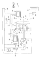
- FIGS. 1 to 3 show three modes of realization of a powertrain 10 in accordance with the invention.
- such a powertrain 10 comprises an epicyclic train 12 whose elements, in particular a planet carrier 14, a sun gear 16, and a ring 18, are linked in rotation to powertrain organs 10 such an output shaft 20 of a heat engine 22, a rotor 24 of a first electric machine 26, a rotor 28 of a second electric machine 30, and a bridge 32 which is intended for drive at least one wheel 34 of the vehicle.
- the two machines 26 and 30 are likely to work either motor or generator, and they are at this title likely to exchange electrical powers with a storage battery 27.
- the rotor 28 of the second electric machine 30 and bridge 32 are linked in rotation to the same element of the planetary gear 12.
- the powertrain 10 includes a command 38 which is capable of controlling the organs of the powertrain 10 according to different operating modes, in particular at least one so-called operating mode "hybrid” during which the heat engine 22 and the electric machines 26, 30 participate in traction and at least a so-called “pure electric” operating mode during which only the electric machines 26, 30 participate in traction.
- the control unit 38 is capable of controlling the operation of the heat engine 22, the operation of a controller 29 of the storage battery 27, operation of the first electric machine 26, and the operation of the second electric machine 18 according to different modes.
- control unit 38 permanently receives information from the various group bodies powertrain 10 and, in response to actuation of a pedal accelerator 31 and by virtue of internal programming, transmits operating instructions for the engine thermal 22, controller 29, battery 27, first electric machine 26, and the second electric machine 30.
- This arrangement is particularly advantageous because it allows in particular to benefit from reduction reports variables.
- the rotor 24 of the first electric machine is linked in rotation to the planetary 14 of the planetary gear 12
- the shaft 20 of the engine thermal is linked to the planet carrier 16 of the planetary gear train 12
- the bridge 32 and the rotor 28 of the second electric machine 30 are both linked in rotation to the crown 18 of the train planetary 12.
- the first electric machine 26 is operating as a generator and the second electric machine 30 operates in engine, there is a powertrain 10 allowing low or medium speeds. If, on the contrary, the first electric machine 26 works as a motor by turning in the opposite direction to the heat engine 14, and if the second electric machine 30 works as a generator, high speed of the crown 28 of the planetary gear 12 allowing high vehicle speeds.
- the group power train 10 generally comprises at least a controlled coupling device 36 allowing selectively to link in rotation the planetary gear element 12 which is linked to the output shaft 20 of the heat engine 22 with one of the remaining elements of the planetary gear 10 for locking all the elements 14, 16, 18 of the planetary gear train 10 each by relationship to others and thus determine at least one so-called relationship of direct plug.
- the device 36 controlled coupling 36 consists of a clutch controlled which is piloted, just like the other organs powertrain 10, by the control unit 38.
- the powertrain 10 comprises at at least one controlled braking device 40 which is intended to brake the rotor 24 of the first electric machine 26.
- This braking device 40 is also controlled by unit 38 of ordered.
- the rotor 24 of the first electric machine 26 is linked in rotation to the planetary 14 of the train epicyclic 10. This configuration is not limiting of the invention, and the rotor 24 of the first electric machine 26 could be linked to another element of the planetary train, the combination of the first electric machine 26 and a determined element of the planetary gear train 10 depending on the transmission reports sought.
- the rotor 24 of the first electric machine 26 is linked in rotation to the planetary 14 of the planetary gear 10 by means of a gear 42.
- the sun gear 14 is for example produced under the shape of a one-piece tubular element which includes, right to the left of Figure 1, a set of teeth 44 which meshes with the satellites 46 of the planetary gear train 10, a set of teeth 48 which mesh with a pinion 49 carried by the rotor 24 of the first electric machine 26, and a disc 50, coaxial with planetary 14, which is part of the controlled braking device.
- the rotor 28 of the second electric machine 30 and bridge 32 are both linked in rotation to the same output element of the planetary gear 10.
- a drive pinion 35, driven by the bridge 32, and a pinion 33 which is carried by the rotor 28 of the second electric machine 30 both mesh with a pinion 37 which is directly linked in rotation at the crown 18 of the planetary gear 10.
- the output shaft 20 of the heat engine 22 is directly linked in rotation to the holder-16 planetary gear satellites 10.
- the powertrain 10 includes a freewheel device 39 which is mounted on the output shaft 20 of the heat engine 22 so as to prevent it from turning in opposite direction to the normal direction of rotation of the motor 22, especially during purely operating modes of the powertrain for which the engine thermal 22 is stopped.
- the controlled braking device 40 comprises at least a plate 54, which is mounted fixed in rotation relative to a fixed element 56 of the powertrain 10.
- the plate 54 is coaxial with the planetary 14, and is arranged opposite the disc 50.
- the plate 54 and the disc 50 are movable one relative to the other, that is to say that one or the other of the disk 50 and tray 54 is axially movable, so that it can cooperate by friction respectively with the plate 54 or the disc 50 so as to immobilize the planet 14.
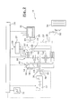
- Figure 2 shows a second embodiment of the invention which is substantially analogous to the first mode of realization previously described, except that the rotor 24 of the first electric machine 26 is coaxial with planetary 14 is directly linked in rotation to the planetary 14 of the planetary gear 10.
- the rotor 24 of the first machine electric 26 is also coaxial with the whole train epicyclic 10. This configuration makes it possible to propose a powertrain 10 which is particularly compact in the axial direction.
- the planetary 14 is for example produced in the form of a one-piece tubular element which comprises, from right to left of Figure 1, the set of teeth 44 which mesh with the satellites 46 of the train epicyclic 10 and a support 59 substantially in the form of disc which carries both the rotor 24 of the first machine electric 26 and a disc 50, part of the device 40 of controlled braking.
- the shaft 52 which is linked to the planet carrier 16 of the planetary gear 12, crosses the planet 14.
- the controlled braking device 40 comprises a plate 54, which is coaxial with a stator 58 of the first electric machine.
- the plate 54 is integral with said stator 58 and it is fixed to the fixed element 56 of the group powertrain 10.
- the disc 50 is arranged opposite the plate 54, and it is coaxial and linked in rotation to the rotor 24 of the first machine electric 26 and planetary 14 of the planetary gear 10.
- the disc 50 and the plate are axially movable relative to each other.
- FIG. 3 represents a third embodiment of the invention which is substantially analogous to the second mode of realization previously described, except that the output shaft 20 of the heat engine 22 is directly linked in rotation at the crown of the planetary gear 10 and that the rotor 28 of the second electric machine 30 and the deck 32 are all two linked in rotation to the planet carrier 16 of the planetary gear 10.
- the planet carrier 16 which forms the exit element of the train planetary 10 is directly linked in rotation to the rotor 28 of the second electric machine 30 and it has a pinion 37 coaxial which meshes with a drive pinion 35 of the deck 32.
- control unit 38 is capable of controlling the controlled braking device 40 and the clutch 36 forming the coupling device controlled to determine different operating modes of the powertrain 10.
- control unit 38 can determine, as previously mentioned, a so-called direct hold mode according to which the controlled braking device 40 is inactive and according to which the controlled clutch device 36 is active to lock all elements 14, 16, 18 of the planetary gear relative to each other and so determine the ratio says direct plug.
- control unit 38 can also determine a so-called reduction mode according to which the braking device 40 controlled is active and according to which the clutch device 36 ordered is inactive.
- the train epicyclic which has its planetary 14 blocked, operates in reducer.
- control unit 38 can determine a mode said of parking, according to which the braking device 40 controlled is active and according to which the clutch device 36 ordered is active. In this configuration, all the elements 14, 16, 18 of the planetary gear 10 are immobilized and therefore the bridge 32 and the wheels 34 are immobilized.
- the invention therefore advantageously makes it possible to benefit a particularly compact powertrain offering many possibilities of obtaining reports of reduction, while offering performance similar to that of a conventional vehicle with thermal engine for high speeds, with the advantage of reduced consumption and pollution.
Abstract
Description
L'invention concerne un groupe motopropulseur de véhicule automobile à motorisation hybride.The invention relates to a power train of motor vehicle with hybrid motorization.
L'invention concerne plus particulièrement un groupe motopropulseur de véhicule automobile à motorisation hybride fonctionnant selon plusieurs modes, du type dans lequel des éléments d'un train épicycloïdal tels qu'une couronne, un planétaire, et un porte-satellites sont liés en rotation à des organes du groupe motopropulseur tels qu'un arbre de sortie d'un moteur thermique, un rotor d'une première machine électrique susceptible de fonctionner indifféremment en moteur ou en générateur, un rotor d'une deuxième machine électrique susceptible de fonctionner indifféremment en moteur ou en générateur, et un pont destiné à transmettre une puissance motrice à des roues du véhicule, et du type dans lequel le rotor de la deuxième machine électrique et le pont sont liés en rotation au même élément du train épicycloïdal.The invention relates more particularly to a group motor vehicle powertrain with hybrid motorization operating in several modes, of the type in which elements of a planetary gear such as a crown, a planetary, and a planet carrier are linked in rotation to powertrain components such as an output shaft of a heat engine, a rotor of a first electric machine capable of operating either as an engine or generator, a rotor of a second electric machine capable of operating either as an engine or generator, and a bridge for transmitting power drive to vehicle wheels, and the type in which the rotor of the second electric machine and the bridge are linked in rotation to the same element of the planetary gear.
On connaít de nombreux exemples de groupes motopropulseurs de ce type.We know many examples of groups powertrains of this type.
Le document EP-A-0.769.403 décrit et représente un groupe motopropulseur de ce type qui est susceptible de fonctionner suivant plusieurs modes, à savoir notamment un mode tout électrique, un mode de fonctionnement thermique permettant la recharge des batteries lorsque le véhicule roule, un mode de fonctionnement hybride, et un mode de rechargement de la batterie à l'arrêt.The document EP-A-0.769.403 describes and represents a powertrain of this type which is likely to operate in several modes, namely in particular a all-electric mode, a thermal operating mode allowing the batteries to be recharged when the vehicle is running, a hybrid operating mode, and a recharging mode battery stopped.
Un problème se pose lorsque le véhicule roule à des vitesses élevées en mode de fonctionnement hybride.A problem arises when the vehicle is driven at high speeds in hybrid operating mode.
En effet, dans cette configuration, la puissance délivrée par le moteur thermique transite obligatoirement par le train épicycloïdal dont les éléments sont mobiles les uns par rapport aux autres.. Indeed, in this configuration, the power delivered by the heat engine must pass through the train epicyclic whose elements are movable relative to each other to others..
Le rendement global du groupe motopropulseur est ainsi grandement altéré par le rendement mécanique du train épicycloïdal ainsi que par le rendement électrique des machines électriques.The overall performance of the powertrain is thus greatly affected by the mechanical performance of the train epicyclic as well as by the electrical efficiency of the machines electric.
Ainsi, une partie de la puissance délivrée par le moteur thermique est elle dissipée en pure perte sous forme de chaleur et de frottement et ne participe pas à la traction du véhicule.So part of the power delivered by the engine is it dissipated in pure loss as heat and friction and does not participate in the traction of the vehicle.
Aussi, pour de grandes vitesses du véhicule, il est nécessaire de pouvoir transmettre la puissance délivrée par le moteur thermique au pont qui entraíne les roues du véhicule, en minimisant les pertes électriques et mécaniques.Also, for high vehicle speeds, it is necessary to be able to transmit the power delivered by the internal combustion engine driving the vehicle wheels, minimizing electrical and mechanical losses.
Dans ce but l'invention propose un groupe motopropulseur permettant de transmettre directement la puissance délivrée par le moteur thermique au pont qui entraíne les roues du véhicule.To this end, the invention proposes a powertrain allowing the power delivered by the engine with the bridge which drives the wheels of the vehicle.
Dans ce but, l'invention propose un groupe motopropulseur du type précédemment décrit, caractérisé en ce qu'il comporte au moins un dispositif d'accouplement commandé permettant sélectivement de lier en rotation l'élément du train épicycloïdal qui est lié à l'arbre de sortie du moteur thermique avec un des éléments restants du train épicycloïdal pour verrouiller tous les éléments du train épicycloïdal les uns par rapport aux autres et déterminer ainsi au moins un rapport dit de prise directe.To this end, the invention provides a powertrain of the type previously described, characterized in that it includes at least one controlled coupling device selectively linking the train element in rotation planetary which is linked to the output shaft of the heat engine with one of the remaining elements of the planetary gear train for lock all the planetary gear elements together relationship to others and thus determine at least one so-called relationship of direct plug.
Selon d'autres caractéristiques de l'invention :
- le groupe motopropulseur comporte au moins un dispositif de freinage commandé qui est destiné à freiner le rotor de la première machine électrique,
- le dispositif d'accouplement est un embrayage commandé,
- le rotor de la première machine électrique est lié en rotation au planétaire du train épicycloïdal,
- le rotor de la première machine électrique est lié en rotation au planétaire du train épicycloïdal par l'intermédiaire d'un engrenage,
- le dispositif de freinage commandé comporte au moins un plateau, qui est monté fixe à rotation par rapport à un élément fixe du groupe motopropulseur, coaxialement au planétaire, et un disque, agencé en regard du plateau et mobile axialement par rapport à celui-ci, qui est coaxial et lié en rotation au planétaire du train épicycloïdal,
- le rotor de la première machine électrique est coaxial et lié en rotation au planétaire du train épicycloïdal,
- le dispositif de freinage commandé comporte au moins un plateau, qui est coaxial et lié à un stator de la première machine électrique, et un disque, agencé en regard du plateau et mobile axialement par rapport à celui-ci, qui est coaxial et lié en rotation au rotor de la première machine électrique et au planétaire du train épicycloïdal,
- l'élément de sortie du train épicycloïdal comporte un pignon coaxial qui engrène simultanément avec un pignon porté par le rotor de la deuxième machine électrique et avec un pignon d'attaque du pont,
- l'élément de sortie du train épicycloïdal est directement lié en rotation au rotor de la deuxième machine électrique et il comporte un pignon coaxial qui engrène un pignon d'attaque du pont,
- l'arbre de sortie du moteur thermique est lié en rotation au porte-satellites du train épicycloïdal, et le rotor de la deuxième machine électrique et le pont sont tous deux liés en rotation à la couronne du train épicycloïdal,
- l'arbre de sortie du moteur thermique est lié en rotation à la couronne du train épicycloïdal, et le rotor de la deuxième machine électrique et le pont sont tous deux liés en rotation au porte-satellites du train épicycloïdal,
- le groupe motopropulseur comporte un dispositif de roue libre interposé entre l'arbre de sortie du moteur thermique et le dispositif d'accouplement commandé,
- le groupe motopropulseur comporte une unité de
commande qui est susceptible de commander le dispositif de
freinage commandé et le dispositif d'accouplement commandé
pour déterminer au moins :
- un mode dit de prise directe selon lequel le dispositif de freinage commandé est inactif et selon lequel le dispositif d'embrayage commandé est actif pour verrouiller tous les éléments du train épicycloïdal les uns par rapport aux autres et déterminer ainsi le rapport dit de prise directe.
- un mode dit de réduction selon lequel le dispositif de freinage commandé est actif et selon lequel le dispositif d'embrayage commandé est inactif pour faire fonctionner le train épicycloïdal en réducteur,
- un mode dit de parking, selon lequel le dispositif de freinage commandé est actif et selon lequel le dispositif d'embrayage commandé est actif pour immobiliser le train épicycloïdal et le pont.
- the powertrain includes at least one controlled braking device which is intended to brake the rotor of the first electric machine,
- the coupling device is a controlled clutch,
- the rotor of the first electric machine is linked in rotation to the planetary of the planetary gear train,
- the rotor of the first electric machine is linked in rotation to the planetary of the planetary gear train by means of a gear,
- the controlled braking device comprises at least one plate, which is mounted fixed in rotation relative to a fixed element of the powertrain, coaxially with the planet, and a disc, arranged opposite the plate and axially movable relative thereto, which is coaxial and linked in rotation to the planetary of the planetary gear,
- the rotor of the first electric machine is coaxial and linked in rotation to the planetary of the planetary gear,
- the controlled braking device comprises at least one plate, which is coaxial and linked to a stator of the first electric machine, and a disc, arranged opposite the plate and movable axially with respect thereto, which is coaxial and linked in rotation of the rotor of the first electric machine and of the planet wheel of the planetary gear,
- the output element of the planetary gear train comprises a coaxial pinion which simultaneously meshes with a pinion carried by the rotor of the second electric machine and with a drive pinion for the bridge,
- the output element of the planetary gear is directly linked in rotation to the rotor of the second electric machine and it comprises a coaxial pinion which meshes with a drive pinion of the bridge,
- the output shaft of the heat engine is linked in rotation to the planet carrier of the planetary gear train, and the rotor of the second electric machine and the bridge are both linked in rotation to the crown of the planetary gear train,
- the output shaft of the heat engine is linked in rotation to the crown of the planetary gear train, and the rotor of the second electric machine and the bridge are both linked in rotation to the planet carrier of the planetary gear train,
- the powertrain includes a freewheel device interposed between the output shaft of the heat engine and the controlled coupling device,
- the powertrain has a control unit which is capable of controlling the controlled braking device and the controlled coupling device to determine at least:
- a so-called direct engagement mode in which the controlled braking device is inactive and in which the controlled clutch device is active in order to lock all the elements of the planetary gear with respect to each other and thus determine the so-called direct engagement ratio.
- a so-called reduction mode according to which the controlled braking device is active and according to which the controlled clutch device is inactive for operating the planetary gear train as a reduction gear,
- a so-called parking mode, according to which the controlled braking device is active and according to which the controlled clutch device is active to immobilize the planetary train and the bridge.
D'autres caractéristiques et avantages de l'invention apparaítront à la lecture de la description détaillée qui suit pour la compréhension de laquelle on se reportera aux dessins annexés dans lesquels :
- la figure 1 est une vue schématique en coupe d'un premier mode de réalisation d'un groupe motopropulseur selon l'invention ;
- la figure 2 est une vue schématique en coupe d'un deuxième mode de réalisation du groupe motopropulseur selon l'invention ; et
- la figure 3 est une vue schématique en coupe d'un premier troisième mode de réalisation du groupe motopropulseur selon l'invention.
- Figure 1 is a schematic sectional view of a first embodiment of a powertrain according to the invention;
- Figure 2 is a schematic sectional view of a second embodiment of the powertrain according to the invention; and
- Figure 3 is a schematic sectional view of a first third embodiment of the powertrain according to the invention.
Dans la description qui va suivre, des chiffres de référence identiques désignent des pièces identiques ou ayant des fonctions similaires. In the description which follows, figures of identical reference designates identical parts or having similar functions.
On a représenté aux figures 1 à 3 trois modes de
réalisation d'un groupe motopropulseur 10 conforme à
l'invention.Figures 1 to 3 show three modes of
realization of a
De manière connue, un tel groupe motopropulseur 10
comporte un train épicycloïdal 12 dont les éléments, notamment
un porte-satellites 14, un planétaire 16, et une couronne 18, sont
liés en rotation à des organes du groupe motopropulseur 10 tels
qu'un arbre 20 de sortie d'un moteur thermique 22, un rotor 24
d'une première machine électrique 26, un rotor 28 d'une
deuxième machine électrique 30, et un pont 32 qui est destiné à
entraíner au moins une roue 34 du véhicule. Les deux machines
électriques 26 et 30 sont susceptibles de fonctionner
indifféremment en moteur ou en un générateur, et elles sont à ce
titre susceptibles d'échanger des puissances électriques avec
une batterie d'accumulateurs 27.In known manner, such a
Par ailleurs, de manière connue, le rotor 28 de la
deuxième machine 30 électrique et le pont 32 sont liés en
rotation au même élément du train épicycloïdal 12.Furthermore, in known manner, the
Le groupe motopropulseur 10 comporte une unité de
commande 38 qui est susceptible de commander les organes du
groupe motopropulseur 10 selon différents modes de fonctionnement,
notamment au moins un mode de fonctionnement dit
"hybride" au cours duquel le moteur thermique 22 et les
machines électriques 26, 30 participent à la traction et au moins
un mode de fonctionnement dit "électrique pur" au cours duquel
seules les machines électriques 26, 30 participent à la traction.
Ainsi, l'unité de commande 38 est susceptible de commander le
fonctionnement du moteur thermique 22, le fonctionnement d'un
contrôleur 29 de la batterie d'accumulateurs 27, le fonctionnement
de la première machine électrique 26, et le fonctionnement
de la deuxième machine électrique 18 selon différents modes. A
cet effet, l'unité de commande 38 reçoit en permanence des
informations en provenance des différents organes du groupe
motopropulseur 10 et, en réponse à l'actionnement d'une pédale
d'accélérateur 31 et en vertu d'une programmation interne, émet
des consignes de fonctionnement à l'intention du moteur
thermique 22, du contrôleur 29 de la batterie 27, de la première
machine électrique 26, et de la deuxième machine électrique 30.The
L'émission de telles consignes étant connue de l'état de la technique, il n'en sera pas fait plus état dans la présente description.The issuance of such instructions being known to the state of the technical, it will not be made more in the present description.
Cette disposition est particulièrement avantageuse car elle permet notamment de bénéficier de rapports de réduction variables.This arrangement is particularly advantageous because it allows in particular to benefit from reduction reports variables.
A titre d'exemple, dans les premier et deuxième modes de
réalisation qui ont été représentés aux figures 1 et 2, le rotor 24
de la première machine électrique est lié en rotation au
planétaire 14 du train épicycloïdal 12, l'arbre 20 du moteur
thermique est lié au porte-satellites 16 du train épicycloïdal 12,
et le pont 32 et le rotor 28 de la deuxième machine électrique 30
sont tous deux liés en rotation à la couronne 18 du train
épicycloïdal 12.By way of example, in the first and second modes of
embodiment which have been represented in FIGS. 1 and 2, the
De ce fait, si la première machine électrique 26 fonctionne
en générateur et la deuxième machine électrique 30 fonctionne
en moteur, on bénéficie d'un groupe motopropulseur 10
autorisant des vitesses faibles ou moyennes. Si, au contraire, la
première machine électrique 26 fonctionne en moteur en tournant
en sens inverse du moteur thermique 14, et si la deuxième
machine électrique 30 fonctionne en générateur, on obtient une
vitesse élevée de la couronne 28 du train épicycloïdal 12
autorisant des vitesses élevées du véhicule.Therefore, if the first
Il importe, dans un tel groupe motopropulseur 10, de
pouvoir bénéficier d'un rapport de transmission dit "long"
permettant de réduire la consommation du moteur thermique 22
sur les parcours de type routier ou autoroutier.It is important, in such a
Dans ce but, conformément à l'invention, le groupe
motopropulseur 10 comporte d'une manière générale au moins
un dispositif 36 d'accouplement commandé permettant
sélectivement de lier en rotation l'élément du train épicycloïdal
12 qui est lié à l'arbre 20 de sortie du moteur thermique 22 avec
un des éléments restants du train épicycloïdal 10 pour verrouiller
tous les éléments 14, 16, 18 du train épicycloïdal 10 les uns par
rapport aux autres et déterminer ainsi au moins un rapport dit de
prise directe.To this end, in accordance with the invention, the
Dans les modes de réalisation préférés de l'invention qui
ont été représentés aux figures 1 à 3, le dispositif 36
d'accouplement commandé 36 est constitué d'un embrayage
commandé qui est piloté, au même titre que les autres organes
du groupe motopropulseur 10, par l'unité 38 de commande.In the preferred embodiments of the invention which
have been shown in Figures 1 to 3, the
Par ailleurs, le groupe motopropulseur 10 comporte au
moins un dispositif 40 de freinage commandé qui est destiné à
freiner le rotor 24 de la première machine électrique 26. Ce
dispositif 40 de freinage est aussi commandé par l'unité 38 de
commande.Furthermore, the
Dans les modes de réalisation préférés de l'invention qui
ont été représentés aux figures 1 à 3, le rotor 24 de la première
machine électrique 26 est lié en rotation au planétaire 14 du train
épicycloïdal 10. Cette configuration n'est pas limitative de
l'invention, et le rotor 24 de la première machine électrique 26
pourrait être lié à un autre élément du train épicycloïdal,
l'association de la première machine électrique 26 et d'un
élément déterminé du train épicycloïdal 10 dépendant des
rapports de transmission recherchés.In the preferred embodiments of the invention which
have been shown in Figures 1 to 3, the
Plus particulièrement, selon le premier mode de
réalisation qui est représenté à la figure 1, le rotor 24 de la
première machine électrique 26 est lié en rotation au planétaire
14 du train épicycloïdal 10 par l'intermédiaire d'un engrenage 42.More particularly, according to the first mode of
embodiment which is shown in Figure 1, the
A cet effet, le planétaire 14 est par exemple réalisé sous
la forme d'un élément tubulaire monobloc qui comporte, de la
droite vers la gauche de la figure 1, un jeu de dentures 44 qui
engrène avec les satellites 46 du train épicycloïdal 10, un jeu de
dentures 48 qui engrène avec un pignon 49 porté par le rotor 24
de la première machine électrique 26, et un disque 50, coaxial au
planétaire 14, qui fait partie du dispositif de freinage commandé.For this purpose, the
Un arbre 52, lié au porte-satellites 16 du train épicycloïdal
12, traverse le planétaire 14.A
Par ailleurs, le rotor 28 de la deuxième machine électrique
30 et le pont 32 sont tous deux liés en rotation à un même
élément de sortie du train épicycloïdal 10. En particulier, un
pignon 35 d'attaque, entraíné par le pont 32, et un pignon 33 qui
est porté par le rotor 28 de la deuxième machine électrique 30
engrènent tous deux avec un pignon 37 qui est directement lié en
rotation à la couronne 18 du train épicycloïdal 10.Furthermore, the
Dans ce mode de réalisation, l'arbre de sortie 20 du
moteur thermique 22 est lié directement en rotation au porte-16
satellites du train épicycloïdal 10.In this embodiment, the
De plus, le groupe motopropulseur 10 comporte un
dispositif 39 de roue libre qui est monté sur l'arbre de sortie 20
du moteur thermique 22 de manière à l'empêcher de tourner en
sens inverse du sens normal de rotation du moteur 22,
notamment au cours des modes de fonctionnement purement
électriques du groupe motopropulseur pour lesquelles le moteur
thermique 22 est arrêté.In addition, the
Le dispositif 40 de freinage commandé comporte au moins
un plateau 54, qui est monté fixe à rotation par rapport à un
élément 56 fixe du groupe motopropulseur 10. Le plateau 54 est
coaxial au planétaire 14, et est agencé en regard du disque 50.
Le plateau 54 et le disque 50 sont mobiles l'un par rapport à
l'autre, c'est à dire que l'un ou l'autre des disque 50 et plateau
54 est mobile axialement, de manière à pouvoir coopérer par
friction respectivement avec le plateau 54 ou bien le disque 50
afin d'immobiliser ainsi le planétaire 14.The controlled
Dans cette configuration, comme on le verra
ultérieurement dans la suite de la présente description, lorsque
le dispositif 40 de freinage commandé est inactif et lorsque
l'embrayage 36 formant le dispositif d'accouplement commandé
est actif, les éléments 14, 16, 18 du train épicycloïdal 12 sont
verrouillés les uns par rapport aux autres et la puissance du
moteur thermique 22 peut cheminer directement de l'arbre 20 de
sortie du moteur 22 au pont 32 en passant par le train
épicycloïdal 12 qui se comporte alors comme un accouplement
rigide.In this configuration, as we will see
later in the rest of this description, when
the controlled
La figure 2 représente un deuxième mode de réalisation
de l'invention qui est sensiblement analogue au premier mode de
réalisation précédemment décrit, à cette différence près que le
rotor 24 de la première machine électrique 26 est coaxial au
planétaire 14 est lié directement en rotation au planétaire 14 du
train épicycloïdal 10.Figure 2 shows a second embodiment
of the invention which is substantially analogous to the first mode of
realization previously described, except that the
De préférence, le rotor 24 de la première machine
électrique 26 est de surcroít coaxial à l'ensemble du train
épicycloïdal 10. Cette configuration permet de proposer un
groupe motopropulseur 10 qui est particulièrement compact
suivant la direction axiale.Preferably, the
Dans cette configuration, le planétaire 14 est par exemple
réalisé sous la forme d'un élément tubulaire monobloc qui
comporte, de la droite vers la gauche de la figure 1, le jeu de
dentures 44 qui engrène avec les satellites 46 du train
épicycloïdal 10 et un support 59 sensiblement en forme de
disque qui porte à la fois le rotor 24 de la première machine
électrique 26 et un disque 50, faisant partie du dispositif 40 de
freinage commandé. L'arbre 52, qui est lié au porte-satellites 16
du train épicycloïdal 12, traverse le planétaire 14.In this configuration, the planetary 14 is for example
produced in the form of a one-piece tubular element which
comprises, from right to left of Figure 1, the set of
Par ailleurs, le dispositif 40 de freinage commandé
comporte un plateau 54, qui est coaxial à un stator 58 de la
première machine électrique. Le plateau 54 est solidaire dudit
stator 58 et il est fixé à l'élément fixe 56 du groupe
motopropulseur 10.Furthermore, the controlled
Le disque 50 est agencé en regard du plateau 54, et il est
coaxial et lié en rotation au rotor 24 de la première machine
électrique 26 et au planétaire 14 du train épicycloïdal 10. D'une
manière analogue au mode de réalisation précédent, le disque 50
et le plateau sont mobiles axialement l'un par rapport à l'autre.The
Dans cette configuration, on comprendra que lorsque le
dispositif 40 de freinage commandé est inactif et lorsque
l'embrayage 36 formant le dispositif 36 de freinage est actif, les
éléments 14, 16, 18 du train épicycloïdal 12 sont verrouillés les
uns par rapport aux autres et la puissance du moteur thermique
22 peut cheminer directement de l'arbre 20 de sortie du moteur
22 au pont 32 en passant par le train épicycloïdal 10 qui se
comporte alors comme un accouplement rigide.In this configuration, it will be understood that when the
controlled
La figure 3 représente un troisième mode de réalisation de
l'invention qui est sensiblement analogue au deuxième mode de
réalisation précédemment décrit, à ces différences près que
l'arbre de sortie 20 du moteur thermique 22 est directement lié
en rotation à la couronne du train épicycloïdal 10 et que le rotor
28 de la deuxième machine électrique 30 et le pont 32 sont tous
deux liés en rotation au porte-satellites 16 du train épicycloïdal
10.FIG. 3 represents a third embodiment of
the invention which is substantially analogous to the second mode of
realization previously described, except that
the
Cette configuration permet de proposer des rapports de réduction différents entre les différents éléments du train épicycloïdal 10.This configuration makes it possible to propose reports of different reduction between different elements of the train epicyclic 10.
De préférence, dans ce troisième mode de réalisation, le
porte-satellites 16 qui forme l'élément de sortie du train
épicycloïdal 10 est directement lié en rotation au rotor 28 de la
deuxième machine électrique 30 et il comporte un pignon 37
coaxial qui engrène un pignon 35 d'attaque du pont 32.Preferably, in this third embodiment, the
Avantageusement, quelque soit le mode de réalisation
envisagé, l'unité 38 de commande est susceptible de commander
le dispositif 40 de freinage commandé et l'embrayage 36 formant
le dispositif d'accouplement commandé pour déterminer
différents modes de fonctionnement du groupe motopropulseur
10.Advantageously, whatever the embodiment
envisaged, the
En particulier, l'unité 38 de commande peut déterminer,
comme précédemment évoqué, un mode dit de prise directe
selon lequel le dispositif 40 de freinage commandé est inactif et
selon lequel le dispositif 36 d'embrayage commandé est actif
pour verrouiller tous les éléments 14, 16, 18 du train épicycloïdal
les uns par rapport aux autres et déterminer ainsi le rapport dit
de prise directe.In particular, the
De plus, l'unité 38 de commande peut aussi déterminer un
mode dit de réduction selon lequel le dispositif 40 de freinage
commandé est actif et selon lequel le dispositif 36 d'embrayage
commandé est inactif. Dans cette configuration, le train
épicycloïdal, qui a son planétaire 14 bloqué, fonctionne en
réducteur.In addition, the
Enfin, l'unité 38 de commande peut déterminer un mode
dit de parking, selon lequel le dispositif 40 de freinage
commandé est actif et selon lequel le dispositif 36 d'embrayage
commandé est actif. Dans cette configuration, tous les éléments
14, 16, 18 du train épicycloïdal 10 sont immobilisés et de ce fait
le pont 32 et les roues 34 sont immobilisés.Finally, the
Les autres modes de fonctionnement "électrique pur",
dans lesquels seules les deux machines électriques 26 et 30
participent à la traction, ou "hybride", dans lesquels le moteur
thermique 22 et les deux machines électriques 26 et 30
participent à la traction sont aussi mis en oeuvre dans l'invention.
Toutefois, leur principe étant largement connu de l'état de la
technique, il n'en sera pas fait état de manière plus détaillée
dans la présente description.The other "pure electric" operating modes,
in which only the two
L'invention permet donc avantageusement de bénéficier d'un groupe motopropulseur particulièrement compact et offrant de nombreuses possibilités d'obtentions de rapports de réduction, tout en offrant des performances analogues à celle d'un véhicule conventionnel à moteur thermique pour des vitesses élevées, avec l'avantage de caractéristiques de consommation et de pollution réduites.The invention therefore advantageously makes it possible to benefit a particularly compact powertrain offering many possibilities of obtaining reports of reduction, while offering performance similar to that of a conventional vehicle with thermal engine for high speeds, with the advantage of reduced consumption and pollution.
Claims (13)
caractérisé en ce qu'il comporte un dispositif (39) de roue libre interposé entre l'arbre (20) de sortie du moteur thermique (22) et le dispositif (36) d'accouplement commandé.Powertrain (10) of a motor vehicle with hybrid motorization operating in several modes, of the type in which elements of a planetary gear (12) such as a crown (18), a sun gear (14), and a planet carrier (16) are linked in rotation to organs of the powertrain (10) such as an output shaft (20) of a heat engine (22), a rotor (24) of a first electric machine (26) capable to operate either as an engine or as a generator, a rotor (28) of a second electric machine (30) capable of operating either as an engine or as a generator, and a bridge (32) intended to transmit motive power to the wheels (34 ) of the vehicle, and of the type in which the rotor (28) of the second electric machine (30) and the bridge (32) are linked in rotation to the same output element of the planetary gear train (12), and of the type which comprises at least one controlled coupling device (36) allowing s electively to link in rotation the element of the planetary gear train (10) which is linked to the output shaft (20) of the heat engine (22) with one of the remaining elements of the planetary gear train (12) to lock all the elements (14 , 16, 18) of the planetary gear with respect to each other and thus determine at least one so-called direct setting ratio,
characterized in that it includes a freewheel device (39) interposed between the output shaft (20) of the heat engine (22) and the controlled coupling device (36).
Applications Claiming Priority (2)
| Application Number | Priority Date | Filing Date | Title |
|---|---|---|---|
| FR0110230 | 2001-07-31 | ||
| FR0110230A FR2828140B1 (en) | 2001-07-31 | 2001-07-31 | HYBRID DRIVE GROUP COMPRISING A LOCKABLE EPICYCLOIDAL TRAIN |
Publications (1)
| Publication Number | Publication Date |
|---|---|
| EP1281557A1 true EP1281557A1 (en) | 2003-02-05 |
Family
ID=8866112
Family Applications (1)
| Application Number | Title | Priority Date | Filing Date |
|---|---|---|---|
| EP02291743A Withdrawn EP1281557A1 (en) | 2001-07-31 | 2002-07-11 | Hybrid drivetrain including a lockable planetary gear and one-way clutch |
Country Status (2)
| Country | Link |
|---|---|
| EP (1) | EP1281557A1 (en) |
| FR (1) | FR2828140B1 (en) |
Cited By (11)
| Publication number | Priority date | Publication date | Assignee | Title |
|---|---|---|---|---|
| EP1449701A1 (en) * | 2003-02-24 | 2004-08-25 | Peugeot Citroen Automobiles S.A. | Coupling device between ICE output shaft of hybrid drive vehicle and input shaft of vehicle change speed gear box |
| GB2405129A (en) * | 2003-06-14 | 2005-02-23 | Christopher William Hend Ellis | Infinitely variable transmission |
| WO2006117492A1 (en) * | 2005-05-02 | 2006-11-09 | Peugeot Citroen Automobiles Sa | Method for blocking wheels of a hybrid vehicle when stopped and associated transmission device |
| CN100363651C (en) * | 2005-05-26 | 2008-01-23 | 武汉理工大学 | Double clutch automatic speed changing power coupler |
| DE102006041160A1 (en) * | 2006-09-01 | 2008-09-11 | Audi Ag | Hybrid drive arrangement for motor vehicle, has internal combustion engine and electrical drive machine, which are rigidly linked with each other by summation gear and operate on common output shaft |
| DE102007044107A1 (en) * | 2007-09-15 | 2009-03-19 | Volkswagen Ag | Doubly power-splitting transmission for hybrid vehicle, has differential e.g. planetary gear, exhibiting three differential shafts, where two shafts are coupled with one another by switchable clutch which exhibits adjustable coupling |
| EP2407363A1 (en) * | 2009-03-12 | 2012-01-18 | Toyota Jidosha Kabushiki Kaisha | Device for preventing false lock |
| CN105082977A (en) * | 2014-05-22 | 2015-11-25 | 福特全球技术公司 | Clutch control to enter powersplit hybrid powertrain parallel mode |
| CN105151042A (en) * | 2014-05-22 | 2015-12-16 | 福特全球技术公司 | Entering and exiting parallel operation of a powersplit hybrid powertrain |
| DE102016008173A1 (en) * | 2016-07-02 | 2018-01-04 | Audi Ag | Drive device for a motor vehicle and method for operating a drive device |
| DE102021112914A1 (en) | 2021-05-18 | 2022-11-24 | Bayerische Motoren Werke Aktiengesellschaft | hybrid drive device |
Families Citing this family (2)
| Publication number | Priority date | Publication date | Assignee | Title |
|---|---|---|---|---|
| FR2954257B1 (en) | 2009-12-18 | 2012-04-13 | Solution F | HYBRID POWERTRAIN GROUP. |
| DE102017101650B4 (en) * | 2017-01-27 | 2021-11-04 | Renk Gmbh | Overlay gear, drive arrangement with two drive units and the overlay gear and method for operating the drive arrangement |
Citations (7)
| Publication number | Priority date | Publication date | Assignee | Title |
|---|---|---|---|---|
| DE4124479A1 (en) * | 1991-07-24 | 1993-01-28 | Bayerische Motoren Werke Ag | Hybrid drive esp. for motor vehicle including stepless gear box - connected across clutch consisting of electric machines and three shaft power distribution drive with electric motors working as generator as required |
| US5258651A (en) * | 1992-04-17 | 1993-11-02 | General Motors Corporation | Electrically biased starting reaction device for a power transmission |
| EP0710787A2 (en) * | 1994-11-04 | 1996-05-08 | Aisin Aw Co., Ltd. | Starting system with energy recovery for automotive vehicles |
| EP0769403A2 (en) | 1995-10-18 | 1997-04-23 | Toyota Jidosha Kabushiki Kaisha | Hybrid vehicle drive system having two motor generator units and engine starting means |
| DE19841829A1 (en) * | 1998-09-12 | 2000-03-16 | Daimler Chrysler Ag | Hybrid drive especially for vehicle has stator and rotor each as machine part, one rigidly connected to motor input and other to output of superposition gearbox. |
| FR2786137A1 (en) * | 1998-11-23 | 2000-05-26 | Rachid Hamdani | Hybrid motor vehicle drive with internal combustion engine and motor having electro-mechanical differential coupler |
| FR2814989A1 (en) * | 2000-10-11 | 2002-04-12 | Renault | Propulsion unit, for hybrid automotive vehicle, ships or railway locomotives, has locking/braking unit connected to gear train, and which enables changeover from electric drive to internal combustion engine drive |
-
2001
- 2001-07-31 FR FR0110230A patent/FR2828140B1/en not_active Expired - Fee Related
-
2002
- 2002-07-11 EP EP02291743A patent/EP1281557A1/en not_active Withdrawn
Patent Citations (7)
| Publication number | Priority date | Publication date | Assignee | Title |
|---|---|---|---|---|
| DE4124479A1 (en) * | 1991-07-24 | 1993-01-28 | Bayerische Motoren Werke Ag | Hybrid drive esp. for motor vehicle including stepless gear box - connected across clutch consisting of electric machines and three shaft power distribution drive with electric motors working as generator as required |
| US5258651A (en) * | 1992-04-17 | 1993-11-02 | General Motors Corporation | Electrically biased starting reaction device for a power transmission |
| EP0710787A2 (en) * | 1994-11-04 | 1996-05-08 | Aisin Aw Co., Ltd. | Starting system with energy recovery for automotive vehicles |
| EP0769403A2 (en) | 1995-10-18 | 1997-04-23 | Toyota Jidosha Kabushiki Kaisha | Hybrid vehicle drive system having two motor generator units and engine starting means |
| DE19841829A1 (en) * | 1998-09-12 | 2000-03-16 | Daimler Chrysler Ag | Hybrid drive especially for vehicle has stator and rotor each as machine part, one rigidly connected to motor input and other to output of superposition gearbox. |
| FR2786137A1 (en) * | 1998-11-23 | 2000-05-26 | Rachid Hamdani | Hybrid motor vehicle drive with internal combustion engine and motor having electro-mechanical differential coupler |
| FR2814989A1 (en) * | 2000-10-11 | 2002-04-12 | Renault | Propulsion unit, for hybrid automotive vehicle, ships or railway locomotives, has locking/braking unit connected to gear train, and which enables changeover from electric drive to internal combustion engine drive |
Cited By (20)
| Publication number | Priority date | Publication date | Assignee | Title |
|---|---|---|---|---|
| EP1449701A1 (en) * | 2003-02-24 | 2004-08-25 | Peugeot Citroen Automobiles S.A. | Coupling device between ICE output shaft of hybrid drive vehicle and input shaft of vehicle change speed gear box |
| FR2851518A1 (en) * | 2003-02-24 | 2004-08-27 | Peugeot Citroen Automobiles Sa | COUPLING DEVICE BETWEEN THE MOTOR SHAFT OF A THERMAL ENGINE OF A HYBRID DRIVE GROUP OF A MOTOR VEHICLE AND THE PRIMARY SHAFT OF THE GEARBOX OF THIS VEHICLE |
| GB2405129A (en) * | 2003-06-14 | 2005-02-23 | Christopher William Hend Ellis | Infinitely variable transmission |
| GB2405129B (en) * | 2003-06-14 | 2006-10-18 | Christopher William Hend Ellis | Kinetic energy storage system |
| WO2006117492A1 (en) * | 2005-05-02 | 2006-11-09 | Peugeot Citroen Automobiles Sa | Method for blocking wheels of a hybrid vehicle when stopped and associated transmission device |
| US8055415B2 (en) | 2005-05-02 | 2011-11-08 | Peugeot Citroen Automobiles Sa | Method for blocking wheels of a hybrid vehicle when stopped and associated transmission device |
| CN100363651C (en) * | 2005-05-26 | 2008-01-23 | 武汉理工大学 | Double clutch automatic speed changing power coupler |
| DE102006041160A1 (en) * | 2006-09-01 | 2008-09-11 | Audi Ag | Hybrid drive arrangement for motor vehicle, has internal combustion engine and electrical drive machine, which are rigidly linked with each other by summation gear and operate on common output shaft |
| DE102006041160B4 (en) * | 2006-09-01 | 2018-05-09 | Audi Ag | Hybrid drive arrangement for motor vehicles |
| DE102007044107A1 (en) * | 2007-09-15 | 2009-03-19 | Volkswagen Ag | Doubly power-splitting transmission for hybrid vehicle, has differential e.g. planetary gear, exhibiting three differential shafts, where two shafts are coupled with one another by switchable clutch which exhibits adjustable coupling |
| CN102348586A (en) * | 2009-03-12 | 2012-02-08 | 丰田自动车株式会社 | Device for preventing false lock |
| EP2407363A4 (en) * | 2009-03-12 | 2013-03-13 | Toyota Motor Co Ltd | Device for preventing false lock |
| CN102348586B (en) * | 2009-03-12 | 2014-07-16 | 丰田自动车株式会社 | Device for preventing false lock |
| EP2407363A1 (en) * | 2009-03-12 | 2012-01-18 | Toyota Jidosha Kabushiki Kaisha | Device for preventing false lock |
| CN105082977A (en) * | 2014-05-22 | 2015-11-25 | 福特全球技术公司 | Clutch control to enter powersplit hybrid powertrain parallel mode |
| CN105151042A (en) * | 2014-05-22 | 2015-12-16 | 福特全球技术公司 | Entering and exiting parallel operation of a powersplit hybrid powertrain |
| CN105151042B (en) * | 2014-05-22 | 2019-01-04 | 福特全球技术公司 | Into and exit power dividing hybrid power power drive system parallel running method |
| DE102016008173A1 (en) * | 2016-07-02 | 2018-01-04 | Audi Ag | Drive device for a motor vehicle and method for operating a drive device |
| US10399429B2 (en) | 2016-07-02 | 2019-09-03 | Audi Ag | Drive device for a motor vehicle and method for operating a drive device |
| DE102021112914A1 (en) | 2021-05-18 | 2022-11-24 | Bayerische Motoren Werke Aktiengesellschaft | hybrid drive device |
Also Published As
| Publication number | Publication date |
|---|---|
| FR2828140B1 (en) | 2003-10-03 |
| FR2828140A1 (en) | 2003-02-07 |
Similar Documents
| Publication | Publication Date | Title |
|---|---|---|
| JP3893938B2 (en) | Hybrid vehicle drive structure with transmission | |
| EP1097830B1 (en) | Hybrid drive unit with at least two planetary gearings | |
| EP1453694B9 (en) | Power transmission device with at least two planetary gear trains | |
| EP1281557A1 (en) | Hybrid drivetrain including a lockable planetary gear and one-way clutch | |
| EP1100690B1 (en) | Hybrid engine transmission unit comprising two electrical machines | |
| EP2200880A2 (en) | Coupling device for a hybrid power train that operates in at least two, electrical/combustion - electrical modes, intended for a vehicle | |
| FR2742703A1 (en) | Differential transmission for hybrid powered vehicle | |
| FR2918003A1 (en) | Hybrid traction device for steering system of e.g. crawler transporter, has gearset engaging with heat engine, motor/generator and electric motor, where gearset has two sun gears driven by engine and motor/generator, respectively | |
| FR2774039A1 (en) | Hybrid drive for motor vehicles with braking on the alternator | |
| FR2923420A1 (en) | Motor vehicle e.g. hybrid motor vehicle, has belt drive connecting shaft of engine to electric machine and comprising controlled disengageable pulley, and another belt drive comprising free wheeling pulley received on shaft of engine | |
| EP1337412B1 (en) | Dual-control hybrid engine-transmission unit for a vehicle | |
| EP1094960B1 (en) | Motor vehicle with mechanical and electric generators | |
| FR2783764A1 (en) | Hybrid drive system for motor vehicle includes IC engine and electrical machines, with facility for direct drive from IC engine when required | |
| FR2946292A3 (en) | Power train for motor vehicle, has electrical machine for driving wheels of motor vehicle by speed changing mechanism, and input clutches intercalated between electrical machine and speed changing mechanism | |
| FR2847014A1 (en) | Infinitely variable mechanical transmission with electric control, uses two parallel transmission paths with selective immobilization of gears to determine operating mode | |
| FR2833538A1 (en) | Power transmission device comprises first input/output rotating with output shaft, second input/output rotating with i.c. engine output shaft and third input/output rotating with electric motor rotor | |
| EP4041581B1 (en) | Power transmission assembly and vehicle comprising said assembly | |
| FR2814989A1 (en) | Propulsion unit, for hybrid automotive vehicle, ships or railway locomotives, has locking/braking unit connected to gear train, and which enables changeover from electric drive to internal combustion engine drive | |
| FR2935307A1 (en) | Hybrid vehicle, has speed reducers installed between electrical machines and shafts of rear wheels, where gear ratio of reducers is adapted based on wheel speed to extend operating speed range of machines | |
| FR2792582A1 (en) | Prime mover disposition for hybrid electric vehicle, comprises IC engine, driving one axle, and electric motor, supplied by battery-backed engine-driven alternator | |
| FR2792985A1 (en) | Transversal motor/propelling unit for car has epicyclical gear train mounted downstream of speed changer, and uses common gear train and speed changer shaft to one wheel | |
| EP4096949A1 (en) | Method for managing a deceleration phase of a hybrid-type motor vehicle | |
| WO2003078188A2 (en) | Hybrid engine transmission unit and corresponding control methods | |
| EP4279308A1 (en) | Hybrid drive assembly for a vehicle | |
| WO2003070506A1 (en) | Device for driving motor vehicles, in particular with hybrid propulsion |
Legal Events
| Date | Code | Title | Description |
|---|---|---|---|
| PUAI | Public reference made under article 153(3) epc to a published international application that has entered the european phase |
Free format text: ORIGINAL CODE: 0009012 |
|
| AK | Designated contracting states |
Designated state(s): AT BE BG CH CY CZ DE DK EE ES FI FR GB GR IE IT LI LU MC NL PT SE SK TR |
|
| AX | Request for extension of the european patent |
Extension state: AL LT LV MK RO SI |
|
| 17P | Request for examination filed |
Effective date: 20030716 |
|
| AKX | Designation fees paid |
Designated state(s): BE DE ES GB IT |
|
| STAA | Information on the status of an ep patent application or granted ep patent |
Free format text: STATUS: THE APPLICATION IS DEEMED TO BE WITHDRAWN |
|
| 18D | Application deemed to be withdrawn |
Effective date: 20080201 |