EP4279308A1 - Hybrid drive assembly for a vehicle - Google Patents
Hybrid drive assembly for a vehicle Download PDFInfo
- Publication number
- EP4279308A1 EP4279308A1 EP23173760.2A EP23173760A EP4279308A1 EP 4279308 A1 EP4279308 A1 EP 4279308A1 EP 23173760 A EP23173760 A EP 23173760A EP 4279308 A1 EP4279308 A1 EP 4279308A1
- Authority
- EP
- European Patent Office
- Prior art keywords
- shaft
- electric machine
- reversible electric
- coupling
- output shaft
- Prior art date
- Legal status (The legal status is an assumption and is not a legal conclusion. Google has not performed a legal analysis and makes no representation as to the accuracy of the status listed.)
- Pending
Links
- 238000010168 coupling process Methods 0.000 claims abstract description 197
- 238000005859 coupling reaction Methods 0.000 claims abstract description 197
- 230000008878 coupling Effects 0.000 claims abstract description 196
- 230000002441 reversible effect Effects 0.000 claims abstract description 129
- 230000005540 biological transmission Effects 0.000 claims abstract description 98
- 230000007246 mechanism Effects 0.000 claims description 37
- 239000003638 chemical reducing agent Substances 0.000 claims description 24
- 230000003068 static effect Effects 0.000 claims description 10
- 230000009467 reduction Effects 0.000 claims description 9
- 208000032370 Secondary transmission Diseases 0.000 claims description 8
- 238000003466 welding Methods 0.000 claims description 3
- 239000000543 intermediate Substances 0.000 description 166
- 241000282472 Canis lupus familiaris Species 0.000 description 19
- 230000008859 change Effects 0.000 description 10
- 230000001052 transient effect Effects 0.000 description 10
- 230000001172 regenerating effect Effects 0.000 description 8
- 230000007935 neutral effect Effects 0.000 description 6
- 230000009365 direct transmission Effects 0.000 description 3
- 230000002787 reinforcement Effects 0.000 description 3
- 230000001360 synchronised effect Effects 0.000 description 3
- 230000008901 benefit Effects 0.000 description 2
- 238000000034 method Methods 0.000 description 2
- 230000001681 protective effect Effects 0.000 description 2
- 230000001133 acceleration Effects 0.000 description 1
- 230000006978 adaptation Effects 0.000 description 1
- 230000002457 bidirectional effect Effects 0.000 description 1
- 238000005119 centrifugation Methods 0.000 description 1
- 238000002485 combustion reaction Methods 0.000 description 1
- 230000010354 integration Effects 0.000 description 1
- 230000008929 regeneration Effects 0.000 description 1
- 238000011069 regeneration method Methods 0.000 description 1
- 230000003014 reinforcing effect Effects 0.000 description 1
- 238000004513 sizing Methods 0.000 description 1
- 230000009466 transformation Effects 0.000 description 1
- 230000001131 transforming effect Effects 0.000 description 1
- 230000007704 transition Effects 0.000 description 1
- 238000011144 upstream manufacturing Methods 0.000 description 1
Images


Classifications
-
- B—PERFORMING OPERATIONS; TRANSPORTING
- B60—VEHICLES IN GENERAL
- B60K—ARRANGEMENT OR MOUNTING OF PROPULSION UNITS OR OF TRANSMISSIONS IN VEHICLES; ARRANGEMENT OR MOUNTING OF PLURAL DIVERSE PRIME-MOVERS IN VEHICLES; AUXILIARY DRIVES FOR VEHICLES; INSTRUMENTATION OR DASHBOARDS FOR VEHICLES; ARRANGEMENTS IN CONNECTION WITH COOLING, AIR INTAKE, GAS EXHAUST OR FUEL SUPPLY OF PROPULSION UNITS IN VEHICLES
- B60K6/00—Arrangement or mounting of plural diverse prime-movers for mutual or common propulsion, e.g. hybrid propulsion systems comprising electric motors and internal combustion engines ; Control systems therefor, i.e. systems controlling two or more prime movers, or controlling one of these prime movers and any of the transmission, drive or drive units Informative references: mechanical gearings with secondary electric drive F16H3/72; arrangements for handling mechanical energy structurally associated with the dynamo-electric machine H02K7/00; machines comprising structurally interrelated motor and generator parts H02K51/00; dynamo-electric machines not otherwise provided for in H02K see H02K99/00
- B60K6/20—Arrangement or mounting of plural diverse prime-movers for mutual or common propulsion, e.g. hybrid propulsion systems comprising electric motors and internal combustion engines ; Control systems therefor, i.e. systems controlling two or more prime movers, or controlling one of these prime movers and any of the transmission, drive or drive units Informative references: mechanical gearings with secondary electric drive F16H3/72; arrangements for handling mechanical energy structurally associated with the dynamo-electric machine H02K7/00; machines comprising structurally interrelated motor and generator parts H02K51/00; dynamo-electric machines not otherwise provided for in H02K see H02K99/00 the prime-movers consisting of electric motors and internal combustion engines, e.g. HEVs
- B60K6/22—Arrangement or mounting of plural diverse prime-movers for mutual or common propulsion, e.g. hybrid propulsion systems comprising electric motors and internal combustion engines ; Control systems therefor, i.e. systems controlling two or more prime movers, or controlling one of these prime movers and any of the transmission, drive or drive units Informative references: mechanical gearings with secondary electric drive F16H3/72; arrangements for handling mechanical energy structurally associated with the dynamo-electric machine H02K7/00; machines comprising structurally interrelated motor and generator parts H02K51/00; dynamo-electric machines not otherwise provided for in H02K see H02K99/00 the prime-movers consisting of electric motors and internal combustion engines, e.g. HEVs characterised by apparatus, components or means specially adapted for HEVs
- B60K6/38—Arrangement or mounting of plural diverse prime-movers for mutual or common propulsion, e.g. hybrid propulsion systems comprising electric motors and internal combustion engines ; Control systems therefor, i.e. systems controlling two or more prime movers, or controlling one of these prime movers and any of the transmission, drive or drive units Informative references: mechanical gearings with secondary electric drive F16H3/72; arrangements for handling mechanical energy structurally associated with the dynamo-electric machine H02K7/00; machines comprising structurally interrelated motor and generator parts H02K51/00; dynamo-electric machines not otherwise provided for in H02K see H02K99/00 the prime-movers consisting of electric motors and internal combustion engines, e.g. HEVs characterised by apparatus, components or means specially adapted for HEVs characterised by the driveline clutches
- B60K6/387—Actuated clutches, i.e. clutches engaged or disengaged by electric, hydraulic or mechanical actuating means
-
- B—PERFORMING OPERATIONS; TRANSPORTING
- B60—VEHICLES IN GENERAL
- B60K—ARRANGEMENT OR MOUNTING OF PROPULSION UNITS OR OF TRANSMISSIONS IN VEHICLES; ARRANGEMENT OR MOUNTING OF PLURAL DIVERSE PRIME-MOVERS IN VEHICLES; AUXILIARY DRIVES FOR VEHICLES; INSTRUMENTATION OR DASHBOARDS FOR VEHICLES; ARRANGEMENTS IN CONNECTION WITH COOLING, AIR INTAKE, GAS EXHAUST OR FUEL SUPPLY OF PROPULSION UNITS IN VEHICLES
- B60K6/00—Arrangement or mounting of plural diverse prime-movers for mutual or common propulsion, e.g. hybrid propulsion systems comprising electric motors and internal combustion engines ; Control systems therefor, i.e. systems controlling two or more prime movers, or controlling one of these prime movers and any of the transmission, drive or drive units Informative references: mechanical gearings with secondary electric drive F16H3/72; arrangements for handling mechanical energy structurally associated with the dynamo-electric machine H02K7/00; machines comprising structurally interrelated motor and generator parts H02K51/00; dynamo-electric machines not otherwise provided for in H02K see H02K99/00
- B60K6/20—Arrangement or mounting of plural diverse prime-movers for mutual or common propulsion, e.g. hybrid propulsion systems comprising electric motors and internal combustion engines ; Control systems therefor, i.e. systems controlling two or more prime movers, or controlling one of these prime movers and any of the transmission, drive or drive units Informative references: mechanical gearings with secondary electric drive F16H3/72; arrangements for handling mechanical energy structurally associated with the dynamo-electric machine H02K7/00; machines comprising structurally interrelated motor and generator parts H02K51/00; dynamo-electric machines not otherwise provided for in H02K see H02K99/00 the prime-movers consisting of electric motors and internal combustion engines, e.g. HEVs
- B60K6/22—Arrangement or mounting of plural diverse prime-movers for mutual or common propulsion, e.g. hybrid propulsion systems comprising electric motors and internal combustion engines ; Control systems therefor, i.e. systems controlling two or more prime movers, or controlling one of these prime movers and any of the transmission, drive or drive units Informative references: mechanical gearings with secondary electric drive F16H3/72; arrangements for handling mechanical energy structurally associated with the dynamo-electric machine H02K7/00; machines comprising structurally interrelated motor and generator parts H02K51/00; dynamo-electric machines not otherwise provided for in H02K see H02K99/00 the prime-movers consisting of electric motors and internal combustion engines, e.g. HEVs characterised by apparatus, components or means specially adapted for HEVs
- B60K6/36—Arrangement or mounting of plural diverse prime-movers for mutual or common propulsion, e.g. hybrid propulsion systems comprising electric motors and internal combustion engines ; Control systems therefor, i.e. systems controlling two or more prime movers, or controlling one of these prime movers and any of the transmission, drive or drive units Informative references: mechanical gearings with secondary electric drive F16H3/72; arrangements for handling mechanical energy structurally associated with the dynamo-electric machine H02K7/00; machines comprising structurally interrelated motor and generator parts H02K51/00; dynamo-electric machines not otherwise provided for in H02K see H02K99/00 the prime-movers consisting of electric motors and internal combustion engines, e.g. HEVs characterised by apparatus, components or means specially adapted for HEVs characterised by the transmission gearings
-
- B—PERFORMING OPERATIONS; TRANSPORTING
- B60—VEHICLES IN GENERAL
- B60K—ARRANGEMENT OR MOUNTING OF PROPULSION UNITS OR OF TRANSMISSIONS IN VEHICLES; ARRANGEMENT OR MOUNTING OF PLURAL DIVERSE PRIME-MOVERS IN VEHICLES; AUXILIARY DRIVES FOR VEHICLES; INSTRUMENTATION OR DASHBOARDS FOR VEHICLES; ARRANGEMENTS IN CONNECTION WITH COOLING, AIR INTAKE, GAS EXHAUST OR FUEL SUPPLY OF PROPULSION UNITS IN VEHICLES
- B60K6/00—Arrangement or mounting of plural diverse prime-movers for mutual or common propulsion, e.g. hybrid propulsion systems comprising electric motors and internal combustion engines ; Control systems therefor, i.e. systems controlling two or more prime movers, or controlling one of these prime movers and any of the transmission, drive or drive units Informative references: mechanical gearings with secondary electric drive F16H3/72; arrangements for handling mechanical energy structurally associated with the dynamo-electric machine H02K7/00; machines comprising structurally interrelated motor and generator parts H02K51/00; dynamo-electric machines not otherwise provided for in H02K see H02K99/00
- B60K6/20—Arrangement or mounting of plural diverse prime-movers for mutual or common propulsion, e.g. hybrid propulsion systems comprising electric motors and internal combustion engines ; Control systems therefor, i.e. systems controlling two or more prime movers, or controlling one of these prime movers and any of the transmission, drive or drive units Informative references: mechanical gearings with secondary electric drive F16H3/72; arrangements for handling mechanical energy structurally associated with the dynamo-electric machine H02K7/00; machines comprising structurally interrelated motor and generator parts H02K51/00; dynamo-electric machines not otherwise provided for in H02K see H02K99/00 the prime-movers consisting of electric motors and internal combustion engines, e.g. HEVs
- B60K6/22—Arrangement or mounting of plural diverse prime-movers for mutual or common propulsion, e.g. hybrid propulsion systems comprising electric motors and internal combustion engines ; Control systems therefor, i.e. systems controlling two or more prime movers, or controlling one of these prime movers and any of the transmission, drive or drive units Informative references: mechanical gearings with secondary electric drive F16H3/72; arrangements for handling mechanical energy structurally associated with the dynamo-electric machine H02K7/00; machines comprising structurally interrelated motor and generator parts H02K51/00; dynamo-electric machines not otherwise provided for in H02K see H02K99/00 the prime-movers consisting of electric motors and internal combustion engines, e.g. HEVs characterised by apparatus, components or means specially adapted for HEVs
- B60K6/40—Arrangement or mounting of plural diverse prime-movers for mutual or common propulsion, e.g. hybrid propulsion systems comprising electric motors and internal combustion engines ; Control systems therefor, i.e. systems controlling two or more prime movers, or controlling one of these prime movers and any of the transmission, drive or drive units Informative references: mechanical gearings with secondary electric drive F16H3/72; arrangements for handling mechanical energy structurally associated with the dynamo-electric machine H02K7/00; machines comprising structurally interrelated motor and generator parts H02K51/00; dynamo-electric machines not otherwise provided for in H02K see H02K99/00 the prime-movers consisting of electric motors and internal combustion engines, e.g. HEVs characterised by apparatus, components or means specially adapted for HEVs characterised by the assembly or relative disposition of components
- B60K6/405—Housings
-
- B—PERFORMING OPERATIONS; TRANSPORTING
- B60—VEHICLES IN GENERAL
- B60K—ARRANGEMENT OR MOUNTING OF PROPULSION UNITS OR OF TRANSMISSIONS IN VEHICLES; ARRANGEMENT OR MOUNTING OF PLURAL DIVERSE PRIME-MOVERS IN VEHICLES; AUXILIARY DRIVES FOR VEHICLES; INSTRUMENTATION OR DASHBOARDS FOR VEHICLES; ARRANGEMENTS IN CONNECTION WITH COOLING, AIR INTAKE, GAS EXHAUST OR FUEL SUPPLY OF PROPULSION UNITS IN VEHICLES
- B60K6/00—Arrangement or mounting of plural diverse prime-movers for mutual or common propulsion, e.g. hybrid propulsion systems comprising electric motors and internal combustion engines ; Control systems therefor, i.e. systems controlling two or more prime movers, or controlling one of these prime movers and any of the transmission, drive or drive units Informative references: mechanical gearings with secondary electric drive F16H3/72; arrangements for handling mechanical energy structurally associated with the dynamo-electric machine H02K7/00; machines comprising structurally interrelated motor and generator parts H02K51/00; dynamo-electric machines not otherwise provided for in H02K see H02K99/00
- B60K6/20—Arrangement or mounting of plural diverse prime-movers for mutual or common propulsion, e.g. hybrid propulsion systems comprising electric motors and internal combustion engines ; Control systems therefor, i.e. systems controlling two or more prime movers, or controlling one of these prime movers and any of the transmission, drive or drive units Informative references: mechanical gearings with secondary electric drive F16H3/72; arrangements for handling mechanical energy structurally associated with the dynamo-electric machine H02K7/00; machines comprising structurally interrelated motor and generator parts H02K51/00; dynamo-electric machines not otherwise provided for in H02K see H02K99/00 the prime-movers consisting of electric motors and internal combustion engines, e.g. HEVs
- B60K6/42—Arrangement or mounting of plural diverse prime-movers for mutual or common propulsion, e.g. hybrid propulsion systems comprising electric motors and internal combustion engines ; Control systems therefor, i.e. systems controlling two or more prime movers, or controlling one of these prime movers and any of the transmission, drive or drive units Informative references: mechanical gearings with secondary electric drive F16H3/72; arrangements for handling mechanical energy structurally associated with the dynamo-electric machine H02K7/00; machines comprising structurally interrelated motor and generator parts H02K51/00; dynamo-electric machines not otherwise provided for in H02K see H02K99/00 the prime-movers consisting of electric motors and internal combustion engines, e.g. HEVs characterised by the architecture of the hybrid electric vehicle
- B60K6/48—Parallel type
-
- B—PERFORMING OPERATIONS; TRANSPORTING
- B60—VEHICLES IN GENERAL
- B60K—ARRANGEMENT OR MOUNTING OF PROPULSION UNITS OR OF TRANSMISSIONS IN VEHICLES; ARRANGEMENT OR MOUNTING OF PLURAL DIVERSE PRIME-MOVERS IN VEHICLES; AUXILIARY DRIVES FOR VEHICLES; INSTRUMENTATION OR DASHBOARDS FOR VEHICLES; ARRANGEMENTS IN CONNECTION WITH COOLING, AIR INTAKE, GAS EXHAUST OR FUEL SUPPLY OF PROPULSION UNITS IN VEHICLES
- B60K6/00—Arrangement or mounting of plural diverse prime-movers for mutual or common propulsion, e.g. hybrid propulsion systems comprising electric motors and internal combustion engines ; Control systems therefor, i.e. systems controlling two or more prime movers, or controlling one of these prime movers and any of the transmission, drive or drive units Informative references: mechanical gearings with secondary electric drive F16H3/72; arrangements for handling mechanical energy structurally associated with the dynamo-electric machine H02K7/00; machines comprising structurally interrelated motor and generator parts H02K51/00; dynamo-electric machines not otherwise provided for in H02K see H02K99/00
- B60K6/20—Arrangement or mounting of plural diverse prime-movers for mutual or common propulsion, e.g. hybrid propulsion systems comprising electric motors and internal combustion engines ; Control systems therefor, i.e. systems controlling two or more prime movers, or controlling one of these prime movers and any of the transmission, drive or drive units Informative references: mechanical gearings with secondary electric drive F16H3/72; arrangements for handling mechanical energy structurally associated with the dynamo-electric machine H02K7/00; machines comprising structurally interrelated motor and generator parts H02K51/00; dynamo-electric machines not otherwise provided for in H02K see H02K99/00 the prime-movers consisting of electric motors and internal combustion engines, e.g. HEVs
- B60K6/50—Architecture of the driveline characterised by arrangement or kind of transmission units
- B60K6/54—Transmission for changing ratio
- B60K6/547—Transmission for changing ratio the transmission being a stepped gearing
-
- B—PERFORMING OPERATIONS; TRANSPORTING
- B60—VEHICLES IN GENERAL
- B60W—CONJOINT CONTROL OF VEHICLE SUB-UNITS OF DIFFERENT TYPE OR DIFFERENT FUNCTION; CONTROL SYSTEMS SPECIALLY ADAPTED FOR HYBRID VEHICLES; ROAD VEHICLE DRIVE CONTROL SYSTEMS FOR PURPOSES NOT RELATED TO THE CONTROL OF A PARTICULAR SUB-UNIT
- B60W10/00—Conjoint control of vehicle sub-units of different type or different function
- B60W10/04—Conjoint control of vehicle sub-units of different type or different function including control of propulsion units
- B60W10/08—Conjoint control of vehicle sub-units of different type or different function including control of propulsion units including control of electric propulsion units, e.g. motors or generators
-
- B—PERFORMING OPERATIONS; TRANSPORTING
- B60—VEHICLES IN GENERAL
- B60W—CONJOINT CONTROL OF VEHICLE SUB-UNITS OF DIFFERENT TYPE OR DIFFERENT FUNCTION; CONTROL SYSTEMS SPECIALLY ADAPTED FOR HYBRID VEHICLES; ROAD VEHICLE DRIVE CONTROL SYSTEMS FOR PURPOSES NOT RELATED TO THE CONTROL OF A PARTICULAR SUB-UNIT
- B60W10/00—Conjoint control of vehicle sub-units of different type or different function
- B60W10/18—Conjoint control of vehicle sub-units of different type or different function including control of braking systems
- B60W10/196—Conjoint control of vehicle sub-units of different type or different function including control of braking systems acting within the driveline, e.g. retarders
-
- B—PERFORMING OPERATIONS; TRANSPORTING
- B60—VEHICLES IN GENERAL
- B60W—CONJOINT CONTROL OF VEHICLE SUB-UNITS OF DIFFERENT TYPE OR DIFFERENT FUNCTION; CONTROL SYSTEMS SPECIALLY ADAPTED FOR HYBRID VEHICLES; ROAD VEHICLE DRIVE CONTROL SYSTEMS FOR PURPOSES NOT RELATED TO THE CONTROL OF A PARTICULAR SUB-UNIT
- B60W20/00—Control systems specially adapted for hybrid vehicles
- B60W20/10—Controlling the power contribution of each of the prime movers to meet required power demand
- B60W20/13—Controlling the power contribution of each of the prime movers to meet required power demand in order to stay within battery power input or output limits; in order to prevent overcharging or battery depletion
- B60W20/14—Controlling the power contribution of each of the prime movers to meet required power demand in order to stay within battery power input or output limits; in order to prevent overcharging or battery depletion in conjunction with braking regeneration
-
- B—PERFORMING OPERATIONS; TRANSPORTING
- B60—VEHICLES IN GENERAL
- B60W—CONJOINT CONTROL OF VEHICLE SUB-UNITS OF DIFFERENT TYPE OR DIFFERENT FUNCTION; CONTROL SYSTEMS SPECIALLY ADAPTED FOR HYBRID VEHICLES; ROAD VEHICLE DRIVE CONTROL SYSTEMS FOR PURPOSES NOT RELATED TO THE CONTROL OF A PARTICULAR SUB-UNIT
- B60W30/00—Purposes of road vehicle drive control systems not related to the control of a particular sub-unit, e.g. of systems using conjoint control of vehicle sub-units, or advanced driver assistance systems for ensuring comfort, stability and safety or drive control systems for propelling or retarding the vehicle
- B60W30/18—Propelling the vehicle
- B60W30/18009—Propelling the vehicle related to particular drive situations
- B60W30/18109—Braking
- B60W30/18127—Regenerative braking
-
- B—PERFORMING OPERATIONS; TRANSPORTING
- B60—VEHICLES IN GENERAL
- B60K—ARRANGEMENT OR MOUNTING OF PROPULSION UNITS OR OF TRANSMISSIONS IN VEHICLES; ARRANGEMENT OR MOUNTING OF PLURAL DIVERSE PRIME-MOVERS IN VEHICLES; AUXILIARY DRIVES FOR VEHICLES; INSTRUMENTATION OR DASHBOARDS FOR VEHICLES; ARRANGEMENTS IN CONNECTION WITH COOLING, AIR INTAKE, GAS EXHAUST OR FUEL SUPPLY OF PROPULSION UNITS IN VEHICLES
- B60K6/00—Arrangement or mounting of plural diverse prime-movers for mutual or common propulsion, e.g. hybrid propulsion systems comprising electric motors and internal combustion engines ; Control systems therefor, i.e. systems controlling two or more prime movers, or controlling one of these prime movers and any of the transmission, drive or drive units Informative references: mechanical gearings with secondary electric drive F16H3/72; arrangements for handling mechanical energy structurally associated with the dynamo-electric machine H02K7/00; machines comprising structurally interrelated motor and generator parts H02K51/00; dynamo-electric machines not otherwise provided for in H02K see H02K99/00
- B60K6/20—Arrangement or mounting of plural diverse prime-movers for mutual or common propulsion, e.g. hybrid propulsion systems comprising electric motors and internal combustion engines ; Control systems therefor, i.e. systems controlling two or more prime movers, or controlling one of these prime movers and any of the transmission, drive or drive units Informative references: mechanical gearings with secondary electric drive F16H3/72; arrangements for handling mechanical energy structurally associated with the dynamo-electric machine H02K7/00; machines comprising structurally interrelated motor and generator parts H02K51/00; dynamo-electric machines not otherwise provided for in H02K see H02K99/00 the prime-movers consisting of electric motors and internal combustion engines, e.g. HEVs
- B60K6/22—Arrangement or mounting of plural diverse prime-movers for mutual or common propulsion, e.g. hybrid propulsion systems comprising electric motors and internal combustion engines ; Control systems therefor, i.e. systems controlling two or more prime movers, or controlling one of these prime movers and any of the transmission, drive or drive units Informative references: mechanical gearings with secondary electric drive F16H3/72; arrangements for handling mechanical energy structurally associated with the dynamo-electric machine H02K7/00; machines comprising structurally interrelated motor and generator parts H02K51/00; dynamo-electric machines not otherwise provided for in H02K see H02K99/00 the prime-movers consisting of electric motors and internal combustion engines, e.g. HEVs characterised by apparatus, components or means specially adapted for HEVs
- B60K6/38—Arrangement or mounting of plural diverse prime-movers for mutual or common propulsion, e.g. hybrid propulsion systems comprising electric motors and internal combustion engines ; Control systems therefor, i.e. systems controlling two or more prime movers, or controlling one of these prime movers and any of the transmission, drive or drive units Informative references: mechanical gearings with secondary electric drive F16H3/72; arrangements for handling mechanical energy structurally associated with the dynamo-electric machine H02K7/00; machines comprising structurally interrelated motor and generator parts H02K51/00; dynamo-electric machines not otherwise provided for in H02K see H02K99/00 the prime-movers consisting of electric motors and internal combustion engines, e.g. HEVs characterised by apparatus, components or means specially adapted for HEVs characterised by the driveline clutches
- B60K2006/381—Arrangement or mounting of plural diverse prime-movers for mutual or common propulsion, e.g. hybrid propulsion systems comprising electric motors and internal combustion engines ; Control systems therefor, i.e. systems controlling two or more prime movers, or controlling one of these prime movers and any of the transmission, drive or drive units Informative references: mechanical gearings with secondary electric drive F16H3/72; arrangements for handling mechanical energy structurally associated with the dynamo-electric machine H02K7/00; machines comprising structurally interrelated motor and generator parts H02K51/00; dynamo-electric machines not otherwise provided for in H02K see H02K99/00 the prime-movers consisting of electric motors and internal combustion engines, e.g. HEVs characterised by apparatus, components or means specially adapted for HEVs characterised by the driveline clutches characterized by driveline brakes
-
- B—PERFORMING OPERATIONS; TRANSPORTING
- B60—VEHICLES IN GENERAL
- B60K—ARRANGEMENT OR MOUNTING OF PROPULSION UNITS OR OF TRANSMISSIONS IN VEHICLES; ARRANGEMENT OR MOUNTING OF PLURAL DIVERSE PRIME-MOVERS IN VEHICLES; AUXILIARY DRIVES FOR VEHICLES; INSTRUMENTATION OR DASHBOARDS FOR VEHICLES; ARRANGEMENTS IN CONNECTION WITH COOLING, AIR INTAKE, GAS EXHAUST OR FUEL SUPPLY OF PROPULSION UNITS IN VEHICLES
- B60K6/00—Arrangement or mounting of plural diverse prime-movers for mutual or common propulsion, e.g. hybrid propulsion systems comprising electric motors and internal combustion engines ; Control systems therefor, i.e. systems controlling two or more prime movers, or controlling one of these prime movers and any of the transmission, drive or drive units Informative references: mechanical gearings with secondary electric drive F16H3/72; arrangements for handling mechanical energy structurally associated with the dynamo-electric machine H02K7/00; machines comprising structurally interrelated motor and generator parts H02K51/00; dynamo-electric machines not otherwise provided for in H02K see H02K99/00
- B60K6/20—Arrangement or mounting of plural diverse prime-movers for mutual or common propulsion, e.g. hybrid propulsion systems comprising electric motors and internal combustion engines ; Control systems therefor, i.e. systems controlling two or more prime movers, or controlling one of these prime movers and any of the transmission, drive or drive units Informative references: mechanical gearings with secondary electric drive F16H3/72; arrangements for handling mechanical energy structurally associated with the dynamo-electric machine H02K7/00; machines comprising structurally interrelated motor and generator parts H02K51/00; dynamo-electric machines not otherwise provided for in H02K see H02K99/00 the prime-movers consisting of electric motors and internal combustion engines, e.g. HEVs
- B60K6/42—Arrangement or mounting of plural diverse prime-movers for mutual or common propulsion, e.g. hybrid propulsion systems comprising electric motors and internal combustion engines ; Control systems therefor, i.e. systems controlling two or more prime movers, or controlling one of these prime movers and any of the transmission, drive or drive units Informative references: mechanical gearings with secondary electric drive F16H3/72; arrangements for handling mechanical energy structurally associated with the dynamo-electric machine H02K7/00; machines comprising structurally interrelated motor and generator parts H02K51/00; dynamo-electric machines not otherwise provided for in H02K see H02K99/00 the prime-movers consisting of electric motors and internal combustion engines, e.g. HEVs characterised by the architecture of the hybrid electric vehicle
- B60K6/48—Parallel type
- B60K2006/4808—Electric machine connected or connectable to gearbox output shaft
-
- B—PERFORMING OPERATIONS; TRANSPORTING
- B60—VEHICLES IN GENERAL
- B60K—ARRANGEMENT OR MOUNTING OF PROPULSION UNITS OR OF TRANSMISSIONS IN VEHICLES; ARRANGEMENT OR MOUNTING OF PLURAL DIVERSE PRIME-MOVERS IN VEHICLES; AUXILIARY DRIVES FOR VEHICLES; INSTRUMENTATION OR DASHBOARDS FOR VEHICLES; ARRANGEMENTS IN CONNECTION WITH COOLING, AIR INTAKE, GAS EXHAUST OR FUEL SUPPLY OF PROPULSION UNITS IN VEHICLES
- B60K6/00—Arrangement or mounting of plural diverse prime-movers for mutual or common propulsion, e.g. hybrid propulsion systems comprising electric motors and internal combustion engines ; Control systems therefor, i.e. systems controlling two or more prime movers, or controlling one of these prime movers and any of the transmission, drive or drive units Informative references: mechanical gearings with secondary electric drive F16H3/72; arrangements for handling mechanical energy structurally associated with the dynamo-electric machine H02K7/00; machines comprising structurally interrelated motor and generator parts H02K51/00; dynamo-electric machines not otherwise provided for in H02K see H02K99/00
- B60K6/20—Arrangement or mounting of plural diverse prime-movers for mutual or common propulsion, e.g. hybrid propulsion systems comprising electric motors and internal combustion engines ; Control systems therefor, i.e. systems controlling two or more prime movers, or controlling one of these prime movers and any of the transmission, drive or drive units Informative references: mechanical gearings with secondary electric drive F16H3/72; arrangements for handling mechanical energy structurally associated with the dynamo-electric machine H02K7/00; machines comprising structurally interrelated motor and generator parts H02K51/00; dynamo-electric machines not otherwise provided for in H02K see H02K99/00 the prime-movers consisting of electric motors and internal combustion engines, e.g. HEVs
- B60K6/42—Arrangement or mounting of plural diverse prime-movers for mutual or common propulsion, e.g. hybrid propulsion systems comprising electric motors and internal combustion engines ; Control systems therefor, i.e. systems controlling two or more prime movers, or controlling one of these prime movers and any of the transmission, drive or drive units Informative references: mechanical gearings with secondary electric drive F16H3/72; arrangements for handling mechanical energy structurally associated with the dynamo-electric machine H02K7/00; machines comprising structurally interrelated motor and generator parts H02K51/00; dynamo-electric machines not otherwise provided for in H02K see H02K99/00 the prime-movers consisting of electric motors and internal combustion engines, e.g. HEVs characterised by the architecture of the hybrid electric vehicle
- B60K6/48—Parallel type
- B60K2006/4816—Electric machine connected or connectable to gearbox internal shaft
-
- B—PERFORMING OPERATIONS; TRANSPORTING
- B60—VEHICLES IN GENERAL
- B60K—ARRANGEMENT OR MOUNTING OF PROPULSION UNITS OR OF TRANSMISSIONS IN VEHICLES; ARRANGEMENT OR MOUNTING OF PLURAL DIVERSE PRIME-MOVERS IN VEHICLES; AUXILIARY DRIVES FOR VEHICLES; INSTRUMENTATION OR DASHBOARDS FOR VEHICLES; ARRANGEMENTS IN CONNECTION WITH COOLING, AIR INTAKE, GAS EXHAUST OR FUEL SUPPLY OF PROPULSION UNITS IN VEHICLES
- B60K6/00—Arrangement or mounting of plural diverse prime-movers for mutual or common propulsion, e.g. hybrid propulsion systems comprising electric motors and internal combustion engines ; Control systems therefor, i.e. systems controlling two or more prime movers, or controlling one of these prime movers and any of the transmission, drive or drive units Informative references: mechanical gearings with secondary electric drive F16H3/72; arrangements for handling mechanical energy structurally associated with the dynamo-electric machine H02K7/00; machines comprising structurally interrelated motor and generator parts H02K51/00; dynamo-electric machines not otherwise provided for in H02K see H02K99/00
- B60K6/20—Arrangement or mounting of plural diverse prime-movers for mutual or common propulsion, e.g. hybrid propulsion systems comprising electric motors and internal combustion engines ; Control systems therefor, i.e. systems controlling two or more prime movers, or controlling one of these prime movers and any of the transmission, drive or drive units Informative references: mechanical gearings with secondary electric drive F16H3/72; arrangements for handling mechanical energy structurally associated with the dynamo-electric machine H02K7/00; machines comprising structurally interrelated motor and generator parts H02K51/00; dynamo-electric machines not otherwise provided for in H02K see H02K99/00 the prime-movers consisting of electric motors and internal combustion engines, e.g. HEVs
- B60K6/42—Arrangement or mounting of plural diverse prime-movers for mutual or common propulsion, e.g. hybrid propulsion systems comprising electric motors and internal combustion engines ; Control systems therefor, i.e. systems controlling two or more prime movers, or controlling one of these prime movers and any of the transmission, drive or drive units Informative references: mechanical gearings with secondary electric drive F16H3/72; arrangements for handling mechanical energy structurally associated with the dynamo-electric machine H02K7/00; machines comprising structurally interrelated motor and generator parts H02K51/00; dynamo-electric machines not otherwise provided for in H02K see H02K99/00 the prime-movers consisting of electric motors and internal combustion engines, e.g. HEVs characterised by the architecture of the hybrid electric vehicle
- B60K6/48—Parallel type
- B60K2006/4833—Step up or reduction gearing driving generator, e.g. to operate generator in most efficient speed range
- B60K2006/4841—Step up or reduction gearing driving generator, e.g. to operate generator in most efficient speed range the gear provides shifting between multiple ratios
-
- F—MECHANICAL ENGINEERING; LIGHTING; HEATING; WEAPONS; BLASTING
- F16—ENGINEERING ELEMENTS AND UNITS; GENERAL MEASURES FOR PRODUCING AND MAINTAINING EFFECTIVE FUNCTIONING OF MACHINES OR INSTALLATIONS; THERMAL INSULATION IN GENERAL
- F16H—GEARING
- F16H3/00—Toothed gearings for conveying rotary motion with variable gear ratio or for reversing rotary motion
Definitions
- the invention relates to a hybrid drive sub-assembly of a vehicle intended to be positioned between an engine, for example a heat engine, and a set of one or more drive wheels of a vehicle. It relates in particular, although not exclusively, to such a subassembly intended to equip a heavy goods vehicle, that is to say a road vehicle of more than 3.5 tonnes, in particular a road tractor.
- the vehicle can also be a coach.
- the invention also relates to a method of braking this vehicle comprising such a hybrid subassembly.
- a hybrid drive sub-assembly of a vehicle comprising a primary shaft intended to be driven by a thermal engine of the vehicle, a secondary shaft intended to drive a set of one or more drive wheels of the vehicle, and a transmission box comprising one or more primary toothed wheels secured in rotation to the primary shaft or capable of being coupled to the primary shaft, a plurality of secondary toothed wheels secured in rotation to the secondary shaft or capable of being coupled to the secondary shaft, and two intermediate shafts to which intermediate toothed wheels are secured in rotation, the primary toothed wheel(s) and the secondary toothed wheels each meshing with a corresponding toothed wheel among the intermediate toothed wheels.
- the hybrid drive subassembly further comprises a reversible electric machine kinematically linked to the intermediate shafts via an upstream reduction stage and a dog clutch coupling mechanism, said electric machine being able to operate as a current generator to brake the shafts intermediates or as a drive motor for the intermediate shafts.
- a reversible electric machine kinematically linked to the intermediate shafts via an upstream reduction stage and a dog clutch coupling mechanism, said electric machine being able to operate as a current generator to brake the shafts intermediates or as a drive motor for the intermediate shafts.
- Such an electric machine makes it possible to envisage different operating modes, and in particular a transient operation of the electric machine to brake or accelerate the intermediate shafts and promote the synchronization of the transmission box in the phases of change of transmission ratio, engine operation to assist the driving of the main engine of the vehicle outside of the gear change phases and operation of an electric generator, for the power supply of vehicle accessories or a battery, in particular during braking phases of the vehicle.
- the reversible electric machine is necessarily kinematically linked to the secondary shaft via the intermediate shaft.
- This connection with the secondary shaft cannot be direct so that certain operating modes are not optimized in terms of mechanical efficiency, in particular the battery regeneration phase.
- the torque coming from the wheels of the vehicle must pass through the entire transmission box to enter the reversible electric machine and allow its operation in electric generator mode.
- the invention aims to remedy the drawbacks of the state of the art and to propose better integration of an electric machine with the intermediate and secondary shafts of a transmission box, making it possible to envisage previously inaccessible modes of operation.
- a hybrid vehicle drive sub-assembly of the type comprising: at least one primary shaft, at least one secondary shaft and a transmission box comprising at least one minus an intermediate shaft distinct from the primary shaft and the secondary shaft and sets of toothed wheels to achieve several transmission ratios between the primary shaft and the secondary shaft passing through the intermediate shaft.
- the hybrid subassembly also comprises an electromotor group comprising at least one reversible electric machine, and a coupling device which, in at least one secondary coupling position, kinematically connects the output shaft of the reversible electric machine to the secondary shaft without passing through the intermediate shaft.
- the hybrid subassembly includes a multi-disc type shaft braking device engaged with the output shaft to brake the secondary shaft when the coupling device is in the secondary coupling position.
- the coupling device allows direct transmission of power between the reversible electric machine and the secondary shaft without driving the intermediate shaft.
- the shaft braking device of the hybrid subassembly ensures the function of slowing down the vehicle when it is on a low percentage slope and for which the driver does not want to use his main braking system.
- the braking capacity of the multi-disc type shaft braking device can be between 20% and 60% of the braking capacity of the reversible electric machine.
- the vehicle slowing function without a shaft braking device would require a high-power reversible electric machine.
- the shaft braking device provides the additional braking of the secondary shaft necessary and helps reduce the sizing of the reversible electric machine while ensuring other operating modes. The cost of the reversible electric machine is thus reduced.
- the shaft braking device may be engaged directly or indirectly with the output shaft.
- the shaft braking device when the shaft braking device is in direct engagement with the output shaft, one of the components of the shaft braking device meshes directly or is driven in rotation directly by the output shaft .
- the shaft braking device When the shaft braking device is in indirect engagement with the output shaft, one of the components of the shaft braking device meshes with a transmission shaft kinematically linked to the output shafts.
- the kinematic connection can be made using a gear, a belt or a transmission chain.
- one of the components of the shaft braking device directly meshes with the associated transmission shaft.
- the shaft braking device engages indirectly with the output shaft by braking the associated transmission shaft.
- the direct transmission of power between the reversible electric machine and the secondary shaft without driving the intermediate shaft also makes it possible to consider other operating modes which will be described later, including: a permanent electric drive mode of the secondary shaft by the reversible electric machine operating as a motor, a transient mode for maintaining traction during gear changes, a pure regenerative braking mode minimizing the resistant mechanical torque.
- the shaft braking device comprises a multi-disc assembly.
- the multi-disc type shaft braking device can be interposed in the direction of conveying the torque between the rotor of the reversible electric machine and the coupling device.
- the multi-disc type shaft braking device can be interposed axially between the rotor of the reversible electric machine and the coupling device.
- the multi-disc type shaft braking device may comprise a rotating disc holder arranged to be linked in rotation with the output shaft, a static disc holder arranged to be linked in rotation with a fixed part of the box transmission and a multi-disc assembly consisting of a first set of discs engaged with splines of the rotating disc carrier, and a second set of discs engaged with splines of the static disc carrier.
- the rotating disc carrier of the shaft braking device can be rotatably connected by spline with the output shaft or rigidly fixed on the output shaft by means of fixing screws, rivets or by welding.
- the shaft braking device can be in indirect engagement with the output shaft of the reversible electric machine by using a speed reducer, the rotating disc carrier being integral in rotation with the output gear of the speed reducer.
- the multi-disc assembly of the shaft braking device can be pressed axially by an actuating piston of annular shape, coaxial with the output shaft of the reversible electric machine, the piston of actuation being guided axially within a pressure chamber formed directly or indirectly in a stator of the reversible electric machine.
- This shaft braking device structure has the advantage of being radially compact and of being able to be easily integrated into a transmission box.
- the multi-disc assembly of the shaft braking device can be pressed axially by an actuating piston of annular shape, coaxial with the output shaft of the reversible electric machine, the piston d the actuation being guided axially within a pressure chamber formed directly or indirectly in the casing of the transmission box.
- the coupling device can be interposed axially between the rotor of the reversible electric machine and the multi-disc type shaft braking device.
- the multi-disc assembly of the shaft braking device can be pressed axially by an actuating piston of annular shape, coaxial with the output shaft of the reversible electric machine, the actuating piston being guided axially within of a pressure chamber formed directly or indirectly in a casing of the transmission box.
- the coupling device may comprise several coupling positions, in particular a first intermediate coupling position, distinct from the secondary coupling position, which kinematically connects the output shaft of the reversible electric machine to the intermediate shaft, and the multi-disc type shaft braking device engaged with the output shaft of the hybrid sub-assembly is arranged to brake the intermediate shaft when the coupling device is in the first intermediate coupling position .
- the coupling device may comprise a plurality of coupling and/or uncoupling positions, for example three distinct coupling positions, allowing power transmission from the reversible electric machine to the intermediate shaft or the shaft secondary according to different transmission ratios.
- the reversible electric machine may in particular be a synchronous machine with permanent magnets, an asynchronous machine, an electric machine with variable reluctance or a synchronous electric machine with variable reluctance, called synchro-reluctant.
- the coupling device in at least one uncoupling position, simultaneously kinematically uncouples the output shaft of the reversible electric machine from the intermediate shaft and the secondary shaft.
- This position of the coupling device makes it possible to implement additional operating modes in which the electrical machine is uncoupled, either because it is not necessary for the operation of the transmission box, or because it is used for other purposes, for example for driving another rotating member.
- Decoupling the machine electric makes it possible to limit the inertia and the resisting torque at the level of the intermediate shaft, and to relieve the guide bearings of its rotor, which increases their lifespan.
- the coupling device comprises at least one coupling mechanism permanently linked kinematically to the output shaft of the reversible electric machine, an intermediate speed reducer permanently linked kinematically to the shaft intermediate and a secondary speed reducer permanently kinematically linked to the secondary shaft.
- the secondary speed reducer can advantageously comprise a reversing toothed wheel guided in rotation by a guide bearing coaxial with the intermediate shaft.
- the coupling device in an additional intermediate coupling position, kinematically connects the reversible electric machine to the intermediate shaft with a ratio of additional intermediate transmission distinct from the intermediate transmission ratio.
- the power take-off member can be coaxial with the intermediate shaft.
- the hybrid subassembly comprises a power take-off member, capable of being driven at least by the reversible electric machine, the power take-off member being permanently kinematically linked to the output shaft of the reversible electric machine.
- the electromotor group can comprise two reversible electric machines each comprising a rotor with an output shaft rotating around an axis of rotation, the two output shafts meshing simultaneously on a common toothed wheel arranged parallel to the two axes of rotation, the shaft braking device being engaged indirectly with the output shafts by braking the associated common toothed wheel.
- the use of two reversible electric machines improves the traction capacity of the vehicle operating in the mode permanent electric drive of the secondary shaft by the reversible electric machine.
- the association of the shaft braking device with the common toothed wheel makes it possible to distribute the braking assistance mode of the vehicle to the two reversible electric machines.
- the transmission box includes coupling mechanisms for alternately coupling each of the primary gears to the primary shaft, and each of the secondary gears to the secondary shaft.
- the hybrid subassembly may also include a friction clutch, dry or wet, intended to be placed between the primary shaft and the main motor.
- the primary shaft and the secondary shaft have coincident axes of revolution. Alternatively these axes are parallel and distant.
- the coupling device comprises an epicyclic gear train arranged kinematically between the output shaft and the secondary shaft.
- the hybrid subassembly can be equipped with a control unit of the reversible electric machine and the coupling device, and sensors capable of generating a signal representative of a speed of revolution of the intermediate shaft or a member which is kinematically linked to it and a signal representative of a speed of revolution of the reversible electric machine or a member which is kinematically linked to it.
- the control unit can in particular be used to synchronize the coupling device.
- control unit is capable, in a state of uncoupling of the coupling device, of controlling the reversible electric machine so that a relative rotation speed between the coupling member kinematically linked to the electric machine reversible and the coupling member kinematically linked to the intermediate shaft achieves a predetermined condition, and, when the predetermined condition is achieved, to control a coupling of the coupling device.
- the predetermined condition could for example be a zero relative rotation speed or a predetermined relative sliding speed.
- the invention comprises a hybrid engine group with a main engine, preferably internal combustion, and a hybrid subassembly as described above.
- the main engine is equipped with a main engine shaft linked to the primary shaft directly or through a clutch or torque converter.
- a braking assistance mode is controlled without intervention of the intermediate shaft, in which the coupling device is positioned in the secondary coupling position, the shaft is uncoupled secondary of the intermediate shaft by acting on the dog clutch mechanisms and simultaneously electrical energy is generated with the reversible electric machine operating as a generator and the shaft braking device is actuated which then applies a braking torque to the output shaft via the pressurized multi-disc assembly.
- a hybrid subassembly 10 for driving a vehicle comprising a primary shaft 12 intended to be driven by a main engine 14 of the vehicle, for example a heat engine, a secondary shaft 16 intended to drive a set of one or more drive wheels of the vehicle (not illustrated), and a transmission box 18.
- connection of the main motor 14 to the primary shaft 12 may include a clutch 20 of any suitable type, for example a slipper clutch.
- connection of the secondary shaft 16 to the wheels of the vehicle may include one or more drive axles.
- the transmission box 18 comprises an intermediate shaft 26 to which intermediate toothed wheels 28, 30, 32, 34, 36 are secured in rotation.
- the meshing of the gear trains 38, 28 and 40, 30 between primary toothed wheels 38, 40 and the corresponding intermediate toothed wheels 28, 30 are permanent.
- a double synchronizer 41 with three positions makes it possible to couple one or the other of the primary toothed wheels 38, 40 to the primary shaft 12, and offers a neutral position in which none of the primary toothed wheels 38, 40 is coupled to the primary shaft 12.
- the different toothed wheels and primary, secondary and intermediate shafts are housed inside a cavity of a casing 24 of the transmission box 18.
- Secondary toothed wheels 42, 44, 46, coaxial with the secondary shaft 16 also each form a gear train with a corresponding toothed wheel 32, 34, 36, respectively, among the intermediate toothed wheels, one of the trains gear being reversing and comprising an intermediate wheel 48 to produce a reverse gear.
- the meshes of the gear trains formed by the secondary toothed wheels 42, 44, 46 and the corresponding intermediate toothed wheels 32, 34, 36 are permanent.
- a three-position dog clutch without synchronizers 50, positioned between two of the secondary wheels 44, 46, allows either one of the two associated secondary wheels 44, 46 to be coupled to the secondary shaft 16 , or, in an intermediate neutral position, to maintain the associated secondary toothed wheels 44, 46 decoupled from the secondary shaft 16.
- the axis of revolution 100 of the primary shaft 12 is aligned with the axis of revolution 200 with the secondary shaft 16, which allows the primary end gear 40 to be used alternatively as primary wheel, associated with the primary shaft 12 by the synchronizer 41, or as a secondary wheel associated with the secondary shaft 16.
- a dog coupling 52 with three positions without synchronizers, positioned between the end primary wheel 40 and the secondary wheel 42, allows coupling to the secondary shaft 16, i.e. the wheel primary end wheel 40 is the secondary wheel 42, and also allows, in an intermediate neutral position, to maintain the primary end wheel 40 and the secondary wheel 42 decoupled from the secondary shaft 16.
- the hybrid drive subassembly 10 is equipped with an electromotor group 5 comprising a reversible electric machine 56, the output shaft 57 of which rotates around an axis of revolution 300, and a device for coupling 58, comprising in this example a dog mechanism 59 with three positions without synchronizer and two reduction trains of toothed wheels 60, 62, 64, 66, 68.
- the coupling device 58 achieves a rotational coupling of the output shaft 57 with a so-called intermediate speed reducer 260 comprising here a toothed wheel 60 which meshes permanently with a toothed wheel 62 secured to the intermediate shaft 26.
- the coupling device 58 couples the output shaft 57 with a so-called secondary speed reducer 264, comprising a toothed wheel 64 which meshes permanently with an inversion toothed wheel 66 which itself meshes permanently with a toothed wheel 68 secured to the secondary shaft 16.
- a so-called secondary speed reducer 264 comprising a toothed wheel 64 which meshes permanently with an inversion toothed wheel 66 which itself meshes permanently with a toothed wheel 68 secured to the secondary shaft 16.
- the toothed wheel of inversion 66 is guided in rotation by a guide bearing 69 coaxial with the intermediate shaft 26.
- the intermediate shaft 26 can then support the guide bearing 69.
- the coupling device 58 in a neutral position, maintains the output shaft 57 decoupled from the toothed wheels 60, 64.
- the transition from the intermediate coupling position to the secondary coupling position takes place via the coupling mechanism 59 controlled by a control unit 76.
- the intermediate shaft 26 is equipped with a power take-off 98, intended to allow coupling of one or more vehicle accessories, for example a winch, a pump or a tool.
- the power take-off 98 can for example be a transmission shaft comprising an external connection interface, for example a spline.
- the output shaft 57 shown on the figure 1 is integral with the rotor of the reversible electric machine 56 and constitutes a motor shaft.
- the reversible electric machine can integrate a reduction gear between the motor shaft and the output shaft 57.
- the reversible electric machine 56 is powered by a battery 70 via a bidirectional current converter 72 , which makes it possible to power the reversible electric machine 56 as a motor, and conversely, to turn the reversible electric machine 56 as a generator to power battery 70.
- the reversible electric machine 56 is preferably a high voltage machine, powered for example at a nominal voltage between 300 Volts and 800 Volts, capable of delivering significant torque and power, as will be discussed later.
- the rated voltage can be higher than 800 volts.
- the control unit 76 makes it possible to control the reversible electric machine 56 and its coupling device 58. To this control unit are connected sensors 78, 80, 82 to measure the speed of revolution of the output shaft 57, of the intermediate shaft 26 and the secondary shaft 16 or the revolution speeds of elements permanently driven by these shafts.
- This control unit 76 can be integrated into a robotic control of the transmission box 18 which controls the opening and closing of the synchronizers 41, the dog mechanisms 50, 52, and where appropriate the main clutch 20, for respond to a torque or speed instruction.
- the electric machine 56 allows several modes of operation to be considered, as will be discussed later.
- the hybrid subassembly 10 also comprises a shaft braking device 90 of the multi-disc type engaged with the output shaft 57 and arranged to brake the secondary shaft 16 when the coupling device 58 is in the position of secondary coupling.
- the shaft braking device 90 comprises a multi-disc assembly 91.
- the shaft braking device 90 of the multi-disc type is interposed, in the direction of transmission of the torque, between the rotor of the reversible electric machine 56 and the device coupling 58.
- the shaft braking device 90 is interposed axially between the rotor of the reversible electric machine 56 and the coupling device 58.
- the multi-disc type shaft braking device 90 comprises a rotating disc holder 92 arranged to be linked in rotation with the output shaft 57, a static disc holder 93 arranged to be linked in rotation with a fixed part of the transmission box 18 and a multi-disc assembly 91 constituted by a first set of discs 91a engaged with splines of the rotating disc carrier, and a second set of discs 91b engaged with splines of the static disc carrier.
- the rotating disc carrier 92 of the shaft braking device 90 is rotatably connected by spline 94 with the output shaft 57.
- the rotating disc carrier 92 can be rigidly fixed on the output shaft 57 via fixing screws, rivets or by welding.
- the multi-disc assembly of the shaft braking device 90 is pressed axially by an actuating piston 95 of annular shape, coaxial with the output shaft 57 of the reversible electric machine 56.
- the actuating piston 95 is guided axially within a pressure chamber 96 formed directly or indirectly in the stator 56a of the reversible electric machine 56.
- the actuating piston 95 can be guided axially within a pressure chamber 96 formed directly or indirectly in the casing of the transmission box 18.
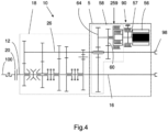
- the coupling device 58 comprises, in addition to the three-position dog clutch coupling mechanism 59, a two-position dog clutch coupling mechanism 159, which achieves rotational coupling of the output shaft 57 with a second intermediate speed reducer 360 comprising a toothed wheel 160 which meshes permanently with a toothed wheel 162 secured to the intermediate shaft 26.
- the transmission ratio produced by the gearing of the toothed wheels 160, 162 is different from the transmission ratio of the gear of the toothed wheels 60, 62.
- the coupling mechanism 159 in a neutral position, keeps the output shaft 57 decoupled from the toothed wheel 160.
- the coupling mechanisms 59, 159 of the coupling device 58 can be of any type, in particular dog clutch with or without synchronization or friction.
- a third embodiment of the invention is thus illustrated, which differs from the example of embodiment of the figure 1 by the fact that the coupling device 58 comprises a coupling mechanism of the wet friction double clutch type 259.
- the coupling device 58 comprises a coupling mechanism of the wet friction triple clutch type 359, producing the same transmission ratios as the exemplary embodiment of the Figure 3 .
- the coupling device comprises a plurality of coupling and uncoupling positions, in particular three distinct coupling positions, allowing power transmission from the reversible electric machine to the intermediate shaft or the secondary shaft according to different transmission ratios.
- the coupling device comprises in particular a first position intermediate coupling position, a second intermediate coupling position otherwise called additional intermediate coupling position and a secondary coupling position.
- the coupling device 58 kinematically connects the reversible electric machine 56 to the intermediate shaft 26 with a second intermediate transmission ratio distinct from the first intermediate transmission ratio.
- the various embodiments described have in common a coupling device 58 capable of taking at least a first so-called intermediate coupling position in which the reversible electric machine 56 is kinematically linked to the intermediate shaft, and at least one position of secondary coupling in which the reversible electric machine 56 is kinematically linked to the secondary shaft 16 without passing through the intermediate shaft 26.
- a braking assistance mode without intervention of the intermediate shaft 26, in which the coupling device 58 is positioned in the secondary coupling position, the secondary shaft 16 is uncoupled from the intermediate shaft 26 by acting on the dog mechanisms 50, 52 and simultaneously, electrical energy is generated with the reversible electric machine 56 operating as a generator and the shaft braking device 90 is actuated which then applies a braking torque to the shaft output 57 via the pressurized multi-disc assembly 91 .
- This braking assistance mode can be advantageous when the vehicle is on a low percentage slope and for which the driver does not want to use his main braking system.
- the braking capacity of the multi-disc type shaft braking device 90 is between 20% and 60% of the braking capacity of the reversible electric machine 56.
- the reversible electric machine To optimally achieve this regenerative braking mode without the main motor, it is advantageous for the reversible electric machine to be able to develop a resistive torque greater than 400 Nm and preferably greater than 450Nm in a speed range of more than 3000 rpm , and preferably more than 4000 rpm having a lower limit which is less than 6500 rpm, and preferably less than 6000 rpm and an upper limit which is greater than 9000 rpm, and preferably greater at 10,000 rpm, for at least 30 seconds.
- the transient mode of maintaining traction during a gear change and the pure regenerative braking mode without the intermediate shaft 26 are transient operating modes, not intended to last more than around thirty seconds.
- the coupling device 58 In a transient mode of synchronization of the intermediate shaft during a gear change, the coupling device 58 is positioned in the first intermediate coupling position, the main motor 14 is uncoupled from the intermediate shaft 26, either at level of the clutch 20, or at the level of the dog mechanism 41, then the reversible electric machine 56 is controlled so as to bring the intermediate shaft 26 to a set speed allowing the engagement of the secondary toothed wheel before recoupling the main engine 14 to the intermediate shaft 26.
- the reversible electric machine 56 thus makes it possible to adapt the speed of revolution of the intermediate shaft to the synchronization needs during switching of the dog mechanisms 50, 52 or the synchronizers 41
- the reversible electric machine can be used alternatively as an electric motor to increase the speed of revolution of the intermediate shaft 26 or as a generator to reduce this speed.
- This adaptation of the speed of the intermediate shaft 26 makes it possible to reduce the interconnection or synchronization times, without having to resort to a gearbox brake.
- one of the primary toothed wheels 38, 40 is coupled to the primary shaft 12, the main motor 14 is powered so as to drive the primary shaft 12 and to exert a main motor torque on the intermediate shaft 26, the coupling device 58 is positioned in the first intermediate coupling position, and the kinetic energy is transformed into electrical energy with the reversible electric machine operating as a generator. Recharging can take place while the intermediate shaft 26 drives the secondary shaft 16 or without connection to the secondary shaft 16.
- one of the secondary gears 42, 44, 46 is coupled to the secondary shaft 16
- one of the primary gears 38, 40 is coupled to the primary shaft
- the main motor 14 is powered so as to drive the primary shaft 12 and to exert a main driving torque on the intermediate shaft 26
- the coupling device 58 is positioned in the first intermediate coupling position or one of the intermediate coupling positions if there are several
- the reversible electric machine generates a reinforcing motor torque on the intermediate shaft, of the same sign as the main motor torque.
- the additional power supply for vehicle traction is achieved with a transmission ratio (for the examples of realization of the figures 1 And 4 ), two transmission ratios (for the examples of realization of the figures 3 And 5 ), or even more.
- the coupling device 58 In a pure electric drive mode passing through the intermediate shaft 26, the coupling device 58 is positioned in the first intermediate coupling position and the main motor 14 is uncoupled from the intermediate shaft 26 while one of the secondary toothed wheels 42, 44, 46 is coupled to the secondary shaft 16, then the reversible electric machine is controlled according to a vehicle speed setpoint.
- the reversible electric machine to be able to continuously develop a motor torque greater than 300 Nm, and preferably greater than 350 Nm, in a range of speed of more than 1000 rpm, and preferably more than 2000 rpm inclusive, having a lower limit which is less than 6000 rpm, and preferably less than 5000 rpm, and an upper limit which is greater at 6000 rpm, preferably greater than 7000 rpm, and preferably greater than 9000 rpm.
- a motor torque greater than 300 Nm, and preferably greater than 350 Nm, in a range of speed of more than 1000 rpm, and preferably more than 2000 rpm inclusive, having a lower limit which is less than 6000 rpm, and preferably less than 5000 rpm, and an upper limit which is greater at 6000 rpm, preferably greater than 7000 rpm, and preferably greater than 9000 rpm.
- the coupling device 58 In a regenerative braking mode passing through the intermediate shaft, the coupling device 58 is positioned in the first intermediate coupling position, the main motor 14 is decoupled from the intermediate shaft 26, at the level of the clutch 20 or synchronizers 41, one of the clutches 50, 52 is engaged to connect the intermediate shaft 26 to the secondary shaft 16 and the reversible electric machine 56 is controlled to operate as a generator.
- the coupling device 58 In a hybrid motor braking mode, the coupling device 58 is positioned in the first intermediate coupling position, a kinematic connection is maintained between the main motor 14, the intermediate shaft 26 and the secondary shaft 16, we transform part of the kinetic energy transmitted by the secondary shaft 16 into electrical energy with the reversible electric machine 56 operating as a generator and part of the kinetic energy transmitted by the secondary shaft 16 is transformed into heat with the main motor 14 developing a resisting torque.
- This mode of operation makes it possible to achieve a greater braking torque than with the main motor 14 alone.
- reversible electric machine 56 as a motor to drive the power take-off 98 while the transmission box 18 is in position neutral to interrupt the connection between the intermediate shaft 26 and the primary shaft 12 on the one hand, and between the intermediate shaft 26 and the secondary shaft 16 on the other hand.
- FIG. 6 On the Figure 6 is illustrated a fifth embodiment of the invention, which differs from the first embodiment by the use of two reversible electric machines 56, each electric machine comprising a stator and a rotor having an output shaft movable in rotation around an axe.
- the reversible electric machines 56 are of the same type and are for example synchronous machines with permanent magnets. Each electrical machine provides the same nominal mechanical power.
- the first electric machine 56 presents in the example described a rotor with a first output shaft 57 rotating around a first axis of rotation X1
- the second electric machine 56 presents a rotor with a second output shaft 57 rotating around 'a second axis of rotation X2.
- the axes of rotation of the reversible electric machines are parallel but not coincident, the two electric machines 56a, 56b not having their axes of rotation aligned.
- the output shafts 57 of the two electric machines mesh simultaneously with a common toothed wheel 110 arranged between the axes X1, X2.
- the common toothed wheel 110 is kinematically linked to the two output shafts and receives the motor torque supplied by the two electrical machines, these being distributed around the common toothed wheel 110 so as to form a first speed reducer Z1, Z2.
- the common toothed wheel 110 is kinematically linked with a transmission shaft 55 specific to the coupling device 58 of this fifth embodiment of the invention using a second speed reducer Z3, Z4.
- the coupling device 58 comprises a dog mechanism 59 with three positions without a synchronizer and two reduction trains of toothed wheels 60, 62, 64, 66, 68.
- the coupling device 58 achieves a rotational coupling of the transmission shaft 55 with a so-called intermediate speed reducer 260 comprising here a toothed wheel 60 which meshes permanently with a toothed wheel 62 secured to the intermediate shaft 26.
- the coupling device 58 couples the transmission shaft 55 with a so-called secondary speed reducer 264, comprising a toothed wheel 64 which meshes permanently with a reversing toothed wheel 66 which itself meshes permanently with a toothed wheel 68 secured to the secondary shaft 16.
- the hybrid subassembly 10 also comprises a multi-disc type shaft braking device 90 engaged with the output shafts 57 of the two electrical machines via the common toothed wheel 110 and arranged to brake the secondary shaft 16 when the coupling device 58 is in the secondary coupling position.
- the shaft braking device 90 comprises a multi-disc assembly 91.
- the shaft braking device 90 of the multi-disc type is interposed, in the direction of transmission of the torque, between the rotor of the reversible electric machine 56 and the device coupling 58.
- the multi-disc type shaft braking device 90 comprises a rotating disc holder 92 arranged to be linked in rotation with the common toothed wheel 110 of axis of rotation 111, a static disc holder 93 arranged to be linked in rotation with a fixed part of the transmission box and a multi-disc assembly 91 constituted by a first set of discs engaged with splines of the rotating disc carrier, and a second set of discs engaged with splines of the static disc carrier.
- the rotating disc carrier 92 of the shaft braking device 90 is linked in rotation by splines with the common toothed wheel 110.
- THE figures 7 And 8 illustrate a sixth embodiment of the invention, which differs from the first embodiment in that the shaft braking device 90 is in indirect engagement with the output shaft 57 of the reversible electric machine 56, in particular by the use of a speed reducer.
- the reversible electric machine 56 comprises an output shaft 57 rotating around an axis of rotation X1, the latter rotating a transmission shaft 55 via a first speed reducer Z1, Z2.
- the transmission shaft 55 includes a coupling device 58.
- the coupling device 58 comprises a dog mechanism 59 with three positions without a synchronizer and two reduction trains of toothed wheels 60, 62, 64, 66, 68.
- the coupling device 58 achieves a rotational coupling of the transmission shaft 55 with a so-called intermediate speed reducer 260 comprising here a toothed wheel 60 which meshes permanently with a toothed wheel 62 secured to the intermediate shaft 26.
- the coupling device 58 couples the transmission shaft 55 with a so-called secondary speed reducer 264, comprising a toothed wheel 64 which meshes permanently with a reversing toothed wheel 66 which itself meshes permanently with a toothed wheel 68 secured to the secondary shaft 16.
- the hybrid subassembly 10 also comprises a shaft braking device 90 of the multi-disc type engaged with the transmission shaft 55 and arranged to brake the secondary shaft 16 when the coupling device 58 is in the position of secondary coupling.
- the shaft braking device 90 comprises a multi-disc assembly 91.
- the shaft braking device 90 of the multi-disc type is interposed, in the direction of transmission of the torque, between the rotor of the reversible electric machine 56 and the device coupling 58.
- the multi-disc type shaft braking device 90 comprises a rotating disc holder 92 engaged with the transmission shaft 55, a static disc holder 93 arranged to be linked in rotation with a fixed part of the transmission box and a multi-disc assembly 91 constituted by a first set of disks engaged with grooves of the rotating disk holder, and a second set of disks engaged with grooves of the static disk holder.
- the rotating disc carrier 92 of the shaft braking device 90 is linked in rotation by splines with the transmission shaft 55.
- the shaft braking device 90 is in indirect engagement with the output shaft 57 of the reversible electric machine by use of a speed reducer Z1, Z2, the rotating disc carrier 92 being integral in rotation of the output pinion Z2 of the speed reducer.
- the dimensioning of the shaft braking device takes into account the reduction ratio associated with the speed reducer Z1, Z2. The risk of centrifugation of the multi-disc assembly 91 of the shaft braking device 90 is limited due to the reduction in the rotation speed.
- the intermediate shaft 26 is equipped with a power take-off 98, intended to allow coupling of one or more vehicle accessories, for example a winch, a pump or a tool.
- the power take-off 98 can for example be a transmission shaft comprising an external connection interface, for example a spline as illustrated in the figure 8 .
- the electric machine is here electrically powered by an inverter 6 for transforming direct electric current into alternating electric current, the inverter comprising a set 6a of electrical components for said transformation and a protective housing 6b accommodating the set of electrical components.
- the inverter protection box 6b is integrated directly into the protective casing of the reversible electric machine 56.
- the inverter 6 is arranged axially along the axis X1 parallel to the reversible electric machine 56.
- the transmission shaft of the power take-off 98 is also oriented parallel to the axis X1 of the reversible electric machine 56.
Abstract
Un sous-ensemble hybride (10) d'entraînement d'un véhicule, comporte au moins un arbre primaire (12), au moins un arbre secondaire (16), une boîte de transmission (18) comportant au moins un arbre intermédiaire (26) distinct de l'arbre primaire (12) et de l'arbre secondaire (16), et un groupe électromoteur comportant au moins une machine électrique réversible (56), et un dispositif d'accouplement (58) qui, dans au moins une position d'accouplement secondaire, lie cinématiquement l'arbre de sortie (57) de la machine électrique réversible (56) à l'arbre secondaire (16) sans passer par l'arbre intermédiaire (26),ledit sous-ensemble hybride comprenant un dispositif de freinage d'arbre (90) de type multidisque en prise avec l'arbre de sortie (57) et agencé pour freiner l'arbre secondaire (16) lorsque le dispositif d'accouplement est dans la position d'accouplement secondaire.A hybrid sub-assembly (10) for driving a vehicle comprises at least one primary shaft (12), at least one secondary shaft (16), a transmission box (18) comprising at least one intermediate shaft (26). ) distinct from the primary shaft (12) and the secondary shaft (16), and an electromotor group comprising at least one reversible electric machine (56), and a coupling device (58) which, in at least one secondary coupling position, kinematically connects the output shaft (57) of the reversible electric machine (56) to the secondary shaft (16) without passing through the intermediate shaft (26), said hybrid subassembly comprising a multi-disc type shaft braking device (90) engaged with the output shaft (57) and arranged to brake the secondary shaft (16) when the coupling device is in the secondary coupling position.
Description
L'invention se rapporte à un sous-ensemble hybride d'entraînement d'un véhicule destiné à être positionné entre un moteur, par exemple un moteur thermique, et un ensemble d'une ou plusieurs roues motrices d'un véhicule. Elle se rapporte en particulier, bien que de façon non exclusive, à un tel sous-ensemble destiné à équiper un poids lourd, c'est-à-dire un véhicule routier de plus de 3,5 tonnes, notamment un tracteur routier. Le véhicule peut également être un autocar. L'invention se rapporte également à un procédé de freinage de ce véhicule comprenant un tel sous-ensemble hybride.The invention relates to a hybrid drive sub-assembly of a vehicle intended to be positioned between an engine, for example a heat engine, and a set of one or more drive wheels of a vehicle. It relates in particular, although not exclusively, to such a subassembly intended to equip a heavy goods vehicle, that is to say a road vehicle of more than 3.5 tonnes, in particular a road tractor. The vehicle can also be a coach. The invention also relates to a method of braking this vehicle comprising such a hybrid subassembly.
Dans le document
Dans le document
Il est donc nécessaire d'envisager une configuration mécanique permettant de lier cinématiquement directement la machine électrique réversible à l'arbre secondaire avec un rapport de démultiplication adapté pour envisager de nouvelles fonctionnalités telle que le mode d'assistance de freinage du véhicule sans intervention de l'arbre intermédiaire.It is therefore necessary to consider a mechanical configuration making it possible to directly link the reversible electric machine kinematically to the secondary shaft with a gear ratio adapted to consider new functionalities such as the vehicle braking assistance mode without intervention of the vehicle. intermediate shaft.
L'invention vise à remédier aux inconvénients de l'état de la technique et à proposer une meilleure intégration d'une machine électrique aux arbres intermédiaire et secondaire d'une boîte de transmission, permettant d'envisager des modes de fonctionnement précédemment inaccessibles.The invention aims to remedy the drawbacks of the state of the art and to propose better integration of an electric machine with the intermediate and secondary shafts of a transmission box, making it possible to envisage previously inaccessible modes of operation.
Pour ce faire est proposé, selon un premier aspect de l'invention, un sous-ensemble hybride d'entraînement d'un véhicule, du type comportant : au moins un arbre primaire, au moins un arbre secondaire et une boîte de transmission comportant au moins un arbre intermédiaire distinct de l'arbre primaire et de l'arbre secondaire et des trains de roues dentées pour réaliser plusieurs rapports de transmission entre l'arbre primaire et l'arbre secondaire en passant par l'arbre intermédiaire. Le sous-ensemble hybride comporte également un groupe électromoteur comportant au moins une machine électrique réversible, et un dispositif d'accouplement qui, dans au moins une position d'accouplement secondaire, lie cinématiquement l'arbre de sortie de la machine électrique réversible à l'arbre secondaire sans passer par l'arbre intermédiaire. De façon remarquable, le sous-ensemble hybride comprend un dispositif de freinage d'arbre de type multidisque en prise avec l'arbre de sortie pour freiner l'arbre secondaire lorsque le dispositif d'accouplement est dans la position d'accouplement secondaire.To do this, according to a first aspect of the invention, a hybrid vehicle drive sub-assembly is proposed, of the type comprising: at least one primary shaft, at least one secondary shaft and a transmission box comprising at least one minus an intermediate shaft distinct from the primary shaft and the secondary shaft and sets of toothed wheels to achieve several transmission ratios between the primary shaft and the secondary shaft passing through the intermediate shaft. The hybrid subassembly also comprises an electromotor group comprising at least one reversible electric machine, and a coupling device which, in at least one secondary coupling position, kinematically connects the output shaft of the reversible electric machine to the secondary shaft without passing through the intermediate shaft. Remarkably, the hybrid subassembly includes a multi-disc type shaft braking device engaged with the output shaft to brake the secondary shaft when the coupling device is in the secondary coupling position.
Il est ainsi avantageux de freiner l'arbre secondaire par rapport à une partie fixe de la boite de transmission lorsque le dispositif d'accouplement est dans la position d'accouplement secondaire. On apporte de manière simple une capacité de freinage supplémentaire au véhicule.It is thus advantageous to brake the secondary shaft relative to a fixed part of the transmission box when the coupling device is in the secondary coupling position. Additional braking capacity is provided in a simple manner to the vehicle.
Dans la position d'accouplement secondaire, le dispositif d'accouplement permet une transmission directe de puissance entre la machine électrique réversible et l'arbre secondaire sans entraînement de l'arbre intermédiaire. Ceci permet d'envisager notamment un mode d'assistance de freinage du véhicule dans lequel le dispositif de freinage d'arbre est agencé pour ralentir l'arbre secondaire. Le dispositif de freinage d'arbre du sous-ensemble hybride permet d'assurer la fonction de ralentissement du véhicule lorsque celui-ci se trouve sur une pente à faible pourcentage et pour lequel le conducteur ne veut pas utiliser son système de freinage principal. Dans ce mode d'assistance de freinage, la capacité de freinage du dispositif de freinage d'arbre de type multidisque peut être comprise entre 20 % et 60 % de la capacité de freinage de la machine électrique réversible. La fonction de ralentissement du véhicule sans dispositif de freinage d'arbre réclamerait une machine électrique réversible de forte puissance. Il est nécessaire de dissiper de l'énergie en grande quantité sur un temps court. La machine électrique réversible utilisée seule pour cette fonction de ralentissement devrait alors avoir des caractéristiques de puissance maximale spécifique pour cette application. Le dispositif de freinage d'arbre apporte le complément de freinage de l'arbre secondaire nécessaire et permet de réduire le dimensionnement de la machine électrique réversible tout en assurant les autres modes de fonctionnement. Le cout de la machine électrique réversible est ainsi réduit.In the secondary coupling position, the coupling device allows direct transmission of power between the reversible electric machine and the secondary shaft without driving the intermediate shaft. This makes it possible to envisage in particular a vehicle braking assistance mode in which the shaft braking device is arranged to slow down the secondary shaft. The shaft braking device of the hybrid subassembly ensures the function of slowing down the vehicle when it is on a low percentage slope and for which the driver does not want to use his main braking system. In this braking assistance mode, the braking capacity of the multi-disc type shaft braking device can be between 20% and 60% of the braking capacity of the reversible electric machine. The vehicle slowing function without a shaft braking device would require a high-power reversible electric machine. It is necessary to dissipate energy in large quantities in a short time. The reversible electric machine used alone for this slowing down function should then have specific maximum power characteristics for this application. The shaft braking device provides the additional braking of the secondary shaft necessary and helps reduce the sizing of the reversible electric machine while ensuring other operating modes. The cost of the reversible electric machine is thus reduced.
De préférence, le dispositif de freinage d'arbre peut être en prise directement ou indirectement avec l'arbre de sortie. Au sens de l'invention, lorsque le dispositif de freinage d'arbre est en prise directe avec l'arbre de sortie, un des constituants du dispositif de freinage d'arbre engrène directement ou est entraîné en rotation directement par l'arbre de sortie. Lorsque le dispositif de freinage d'arbre est en prise indirecte avec l'arbre de sortie, un des constituants du dispositif de freinage d'arbre engrène avec un arbre de transmission lié cinématiquement aux arbres de sortie. La liaison cinématique peut se faire à l'aide d'un engrenage, d'une courroie ou d'une chaîne de transmission. Dans ce deuxième cas, un des constituants du dispositif de freinage d'arbre engrène directement l'arbre de transmission associé. Ainsi, le dispositif de freinage d'arbre est en prise indirectement avec l'arbre de sortie par freinage de l'arbre de transmission associé.Preferably, the shaft braking device may be engaged directly or indirectly with the output shaft. Within the meaning of the invention, when the shaft braking device is in direct engagement with the output shaft, one of the components of the shaft braking device meshes directly or is driven in rotation directly by the output shaft . When the shaft braking device is in indirect engagement with the output shaft, one of the components of the shaft braking device meshes with a transmission shaft kinematically linked to the output shafts. The kinematic connection can be made using a gear, a belt or a transmission chain. In this second case, one of the components of the shaft braking device directly meshes with the associated transmission shaft. Thus, the shaft braking device engages indirectly with the output shaft by braking the associated transmission shaft.
La transmission directe de puissance entre la machine électrique réversible et l'arbre secondaire sans entraînement de l'arbre intermédiaire permet d'envisager également d'autres modes de fonctionnement qui seront décrit plus loin, parmi lesquels : un mode d'entraînement électrique permanent de l'arbre secondaire par la machine électrique réversible fonctionnant en moteur, un mode transitoire de maintien de la traction lors des changements de rapport, un mode de freinage régénératif pur minimisant le couple mécanique résistant.The direct transmission of power between the reversible electric machine and the secondary shaft without driving the intermediate shaft also makes it possible to consider other operating modes which will be described later, including: a permanent electric drive mode of the secondary shaft by the reversible electric machine operating as a motor, a transient mode for maintaining traction during gear changes, a pure regenerative braking mode minimizing the resistant mechanical torque.
De préférence, le dispositif de freinage d'arbre comprend un ensemble multidisques.Preferably, the shaft braking device comprises a multi-disc assembly.
Avantageusement, le dispositif de freinage d'arbre de type multidisque peut être interposé dans le sens d'acheminement du couple entre le rotor de la machine électrique réversible et le dispositif d'accouplement.Advantageously, the multi-disc type shaft braking device can be interposed in the direction of conveying the torque between the rotor of the reversible electric machine and the coupling device.
De préférence, le dispositif de freinage d'arbre de type multidisque peut être interposé axialement entre le rotor de la machine électrique réversible et le dispositif d'accouplement.Preferably, the multi-disc type shaft braking device can be interposed axially between the rotor of the reversible electric machine and the coupling device.
Avantageusement, le dispositif de freinage d'arbre de type multidisque peut comprendre un porte-disques tournant agencé pour être lié en rotation avec l'arbre de sortie, un porte-disques statique agencé pour être lié en rotation avec une partie fixe de la boite de transmission et un ensemble multidisques constitué par un premier jeu de disques en prise avec des cannelures du porte-disques tournant, et un deuxième jeu de disques en prise avec des cannelures du porte-disques statique.Advantageously, the multi-disc type shaft braking device may comprise a rotating disc holder arranged to be linked in rotation with the output shaft, a static disc holder arranged to be linked in rotation with a fixed part of the box transmission and a multi-disc assembly consisting of a first set of discs engaged with splines of the rotating disc carrier, and a second set of discs engaged with splines of the static disc carrier.
Le porte-disques tournant du dispositif de freinage d'arbre peut être lié en rotation par cannelure avec l'arbre de sortie ou fixé rigidement sur l'arbre de sortie par l'intermédiaire de vis de fixation, de rivets ou par soudure.The rotating disc carrier of the shaft braking device can be rotatably connected by spline with the output shaft or rigidly fixed on the output shaft by means of fixing screws, rivets or by welding.
Selon une variante de l'invention, le dispositif de freinage d'arbre peut être en prise indirecte avec l'arbre de sortie de la machine électrique réversible par utilisation d'un réducteur de vitesse, le porte-disques tournant étant solidaire en rotation du pignon de sortie du réducteur de vitesse.According to a variant of the invention, the shaft braking device can be in indirect engagement with the output shaft of the reversible electric machine by using a speed reducer, the rotating disc carrier being integral in rotation with the output gear of the speed reducer.
Selon une variante de l'invention, l'ensemble multidisques du dispositif de freinage d'arbre peut être pressé axialement par un piston d'actionnement de forme annulaire, coaxial à l'arbre de sortie de la machine électrique réversible, le piston d'actionnement étant guidé axialement au sein d'une chambre de pression formée directement ou indirectement dans un stator de la machine électrique réversible. Cette structure de dispositif de freinage d'arbre présente l'avantage d'être compacte radialement et de pouvoir s'intégrer facilement au sein d'une boite de transmission.According to a variant of the invention, the multi-disc assembly of the shaft braking device can be pressed axially by an actuating piston of annular shape, coaxial with the output shaft of the reversible electric machine, the piston of actuation being guided axially within a pressure chamber formed directly or indirectly in a stator of the reversible electric machine. This shaft braking device structure has the advantage of being radially compact and of being able to be easily integrated into a transmission box.
Selon une autre variante de l'invention, l'ensemble multidisques du dispositif de freinage d'arbre peut être pressé axialement par un piston d'actionnement de forme annulaire, coaxial à l'arbre de sortie de la machine électrique réversible, le piston d'actionnement étant guidé axialement au sein d'une chambre de pression formée directement ou indirectement dans le carter de la boite de transmission.According to another variant of the invention, the multi-disc assembly of the shaft braking device can be pressed axially by an actuating piston of annular shape, coaxial with the output shaft of the reversible electric machine, the piston d the actuation being guided axially within a pressure chamber formed directly or indirectly in the casing of the transmission box.
Selon une autre variante de l'invention, le dispositif d'accouplement peut être interposé axialement entre le rotor de la machine électrique réversible et le dispositif de freinage d'arbre de type multidisque.According to another variant of the invention, the coupling device can be interposed axially between the rotor of the reversible electric machine and the multi-disc type shaft braking device.
Avantageusement, l'ensemble multidisques du dispositif de freinage d'arbre peut être pressé axialement par un piston d'actionnement de forme annulaire, coaxial à l'arbre de sortie de la machine électrique réversible, le piston d'actionnement étant guidé axialement au sein d'une chambre de pression formée directement ou indirectement dans un carter de la boite de transmission.Advantageously, the multi-disc assembly of the shaft braking device can be pressed axially by an actuating piston of annular shape, coaxial with the output shaft of the reversible electric machine, the actuating piston being guided axially within of a pressure chamber formed directly or indirectly in a casing of the transmission box.
De préférence, le dispositif d'accouplement peut comprendre plusieurs positions d'accouplement, notamment une première position d'accouplement intermédiaire, distincte de la position d'accouplement secondaire, qui lie cinématiquement l'arbre de sortie de la machine électrique réversible à l'arbre intermédiaire, et le dispositif de freinage d'arbre de type multidisque en prise avec l'arbre de sortie du sous-ensemble hybride est agencé pour freiner l'arbre intermédiaire lorsque le dispositif d'accouplement est dans la première position d'accouplement intermédiaire.Preferably, the coupling device may comprise several coupling positions, in particular a first intermediate coupling position, distinct from the secondary coupling position, which kinematically connects the output shaft of the reversible electric machine to the intermediate shaft, and the multi-disc type shaft braking device engaged with the output shaft of the hybrid sub-assembly is arranged to brake the intermediate shaft when the coupling device is in the first intermediate coupling position .
Le dispositif d'accouplement peut comprendre une pluralité de positions d'accouplement et/ou de désaccouplement, par exemple trois positions d'accouplement distinctes, permettant une transmission de puissance en provenance de la machine électrique réversible vers l'arbre intermédiaire ou l'arbre secondaire selon des rapports de transmission différents.The coupling device may comprise a plurality of coupling and/or uncoupling positions, for example three distinct coupling positions, allowing power transmission from the reversible electric machine to the intermediate shaft or the shaft secondary according to different transmission ratios.
La machine électrique réversible pourra notamment être une machine synchrone à aimants permanents, une machine asynchrone, une machine électrique à réluctance variable ou une machine électrique synchrone à réluctance variable, dite synchro-réluctante.The reversible electric machine may in particular be a synchronous machine with permanent magnets, an asynchronous machine, an electric machine with variable reluctance or a synchronous electric machine with variable reluctance, called synchro-reluctant.
Suivant un mode de réalisation, le dispositif d'accouplement, dans au moins une position de désaccouplement, désaccouple cinématiquement de manière simultanée l'arbre de sortie de la machine électrique réversible à l'arbre intermédiaire et à l'arbre secondaire. Cette position du dispositif d'accouplement permet de mettre en oeuvre des modes de fonctionnement supplémentaires dans lesquels la machine électrique est désaccouplée, soit parce qu'elle n'est pas nécessaire au fonctionnement de la boîte de transmission, soit parce qu'elle est utilisée à d'autres fins, par exemple pour l'entraînement d'un autre organe tournant. Le découplage de la machine électrique permet de limiter l'inertie et le couple résistant au niveau de l'arbre intermédiaire, et de soulager les paliers de guidage de son rotor, ce qui augmente leur durée de vie.According to one embodiment, the coupling device, in at least one uncoupling position, simultaneously kinematically uncouples the output shaft of the reversible electric machine from the intermediate shaft and the secondary shaft. This position of the coupling device makes it possible to implement additional operating modes in which the electrical machine is uncoupled, either because it is not necessary for the operation of the transmission box, or because it is used for other purposes, for example for driving another rotating member. Decoupling the machine electric makes it possible to limit the inertia and the resisting torque at the level of the intermediate shaft, and to relieve the guide bearings of its rotor, which increases their lifespan.
Suivant un mode de réalisation, le dispositif d'accouplement comprend au moins un mécanisme d'accouplement lié cinématiquement de façon permanente à l'arbre de sortie de la machine électrique réversible, un réducteur de vitesse intermédiaire lié cinématiquement de façon permanente à l'arbre intermédiaire et un réducteur de vitesse secondaire liée cinématiquement de façon permanente à l'arbre secondaire. Le réducteur de vitesse secondaire peut avantageusement comprendre une roue dentée d'inversion guidée en rotation par un palier de guidage coaxial avec l'arbre intermédiaire.According to one embodiment, the coupling device comprises at least one coupling mechanism permanently linked kinematically to the output shaft of the reversible electric machine, an intermediate speed reducer permanently linked kinematically to the shaft intermediate and a secondary speed reducer permanently kinematically linked to the secondary shaft. The secondary speed reducer can advantageously comprise a reversing toothed wheel guided in rotation by a guide bearing coaxial with the intermediate shaft.
La machine électrique réversible peut être de préférence dimensionnée de manière à être pleinement opérationnelle pour de larges plages de fonctionnement dans les divers modes de fonctionnement envisagée. Ainsi, on prévoit de façon préférentielle que la machine électrique réversible réponde à un ou plusieurs des critères suivants :
- la machine électrique réversible est apte à développer de façon continue un couple moteur supérieur à 300 Nm, et de préférence supérieure à 350Nm, dans une plage de vitesse de plus de 1000 tr/min, et de préférence de plus de 2000 tr/min comprise ayant une borne inférieure qui est inférieure à 6000 tr/min, et de préférence inférieure à 5000 tr/min, et une borne supérieure qui est supérieure à 6000 tr/min, de préférence supérieure à 7000 tr/min, et de préférence supérieure à 9000 tr/min ;
- la machine électrique réversible est apte à développer un couple résistant supérieur à 400 Nm et de préférence supérieur à 450Nm dans une plage de vitesse de plus de 3000 tr/min, et de préférence de plus de 4000 tr/min ayant une borne inférieure qui est inférieure à 6500 tr/min, et de préférence inférieure à 6000 tr/min et une borne supérieure qui est supérieure à 9000 tr/min, et de préférence supérieure à 10000 tr/min, pendant 30 secondes ;
- la machine électrique réversible est apte à développer un couple moteur supérieur à 50 Nm et de préférence supérieur à 60Nm dans une plage de vitesse de plus de 5500 tr/min, et de préférence de plus de 7000 tr/min ayant une borne inférieure qui est inférieure à 5000 tr/min, et de préférence inférieure à 4500 tr/min et une borne supérieure qui est supérieure à 10000 tr/min, et de préférence supérieure à 11000 tr/min, pendant 5 secondes en régime de transitoire de changement de rapport.
- the reversible electric machine is capable of continuously developing a motor torque greater than 300 Nm, and preferably greater than 350 Nm, in a speed range of more than 1000 rpm, and preferably more than 2000 rpm inclusive having a lower limit which is less than 6000 rpm, and preferably less than 5000 rpm, and an upper limit which is greater than 6000 rpm, preferably greater than 7000 rpm, and preferably greater than 9000 rpm;
- the reversible electric machine is capable of developing a resistant torque greater than 400 Nm and preferably greater than 450 Nm in a speed range of more than 3000 rpm, and preferably more than 4000 rpm having a lower limit which is less than 6500 rpm, and preferably less than 6000 rpm and an upper limit which is greater than 9000 rpm, and preferably greater than 10000 rpm, for 30 seconds;
- the reversible electric machine is capable of developing a motor torque greater than 50 Nm and preferably greater than 60 Nm in a speed range of more than 5500 rpm, and preferably more than 7000 rpm having a lower limit which is less than 5000 rpm, and preferably less than 4500 rpm and an upper limit which is greater than 10000 rpm, and preferably greater than 11000 rpm, for 5 seconds in gear change transient mode .
En pratique, le dispositif d'accouplement dans la première position d'accouplement intermédiaire lie cinématiquement l'arbre de sortie de la machine électrique réversible à l'arbre intermédiaire avec un rapport de transmission dit intermédiaire alors que le dispositif d'accouplement dans la position d'accouplement secondaire lie cinématiquement la machine électrique réversible à l'arbre secondaire avec un rapport de transmission dit secondaire. Suivant un exemple de réalisation, le dispositif d'accouplement répond à un ou plusieurs des critères suivants :
- le rapport de transmission secondaire est supérieur à 6, et de préférence supérieur ou égal à 8 ;
- le rapport de transmission intermédiaire supérieur 4, et de préférence supérieur ou égal à 6 entre l'arbre intermédiaire et l'arbre de sortie de de la machine électrique réversible ;
- le rapport de transmission secondaire est strictement supérieur au rapport de transmission intermédiaire, de préférence avec un facteur supérieur ou égal à 1,5 entre rapport de transmission secondaire et rapport de transmission intermédiaire.
- the secondary transmission ratio is greater than 6, and preferably greater than or equal to 8;
- the upper intermediate transmission ratio 4, and preferably greater than or equal to 6 between the intermediate shaft and the output shaft of the reversible electric machine;
- the secondary transmission ratio is strictly greater than the intermediate transmission ratio, preferably with a factor greater than or equal to 1.5 between secondary transmission ratio and intermediate transmission ratio.
Il peut être avantageux de disposer de plusieurs rapports de transmission entre la machine électrique réversible et l'arbre intermédiaire et/ou entre la machine électrique réversible et l'arbre secondaire. A cette fin, le dispositif d'accouplement, dans une position d'accouplement intermédiaire supplémentaire, lie cinématiquement la machine électrique réversible à l'arbre intermédiaire avec un rapport de transmission intermédiaire supplémentaire distinct du rapport de transmission intermédiaire.It may be advantageous to have several transmission ratios between the reversible electric machine and the intermediate shaft and/or between the reversible electric machine and the secondary shaft. For this purpose, the coupling device, in an additional intermediate coupling position, kinematically connects the reversible electric machine to the intermediate shaft with a ratio of additional intermediate transmission distinct from the intermediate transmission ratio.
Suivant un mode de réalisation particulièrement avantageux, le sous-ensemble hybride comporte en outre un organe de prise de force, apte à être entraîné au moins par la machine électrique réversible, de préférence de l'une des manières suivantes :
- l'organe de prise de force est lié cinématiquement de façon permanente à l'arbre intermédiaire ;
- l'organe de prise de force est lié cinématiquement à l'arbre intermédiaire par l'intermédiaire du dispositif d'accouplement en position d'accouplement intermédiaire ;
- l'organe de prise de force est lié cinématiquement à l'arbre de sortie de la machine électrique réversible par l'intermédiaire du dispositif d'accouplement en position d'accouplement intermédiaire.
- the power take-off member is permanently kinematically linked to the intermediate shaft;
- the power take-off member is kinematically linked to the intermediate shaft via the coupling device in the intermediate coupling position;
- the power take-off member is kinematically linked to the output shaft of the reversible electric machine via the coupling device in the intermediate coupling position.
Suivant ce mode de réalisation, l'organe de prise de force peut être coaxial à l'arbre intermédiaire.According to this embodiment, the power take-off member can be coaxial with the intermediate shaft.
Suivant un autre mode de réalisation particulièrement avantageux, le sous-ensemble hybride comporte un organe de prise de force, apte à être entraîné au moins par la machine électrique réversible, l'organe de prise de force étant lié cinématiquement de façon permanente à l'arbre de sortie de la machine électrique réversible.According to another particularly advantageous embodiment, the hybrid subassembly comprises a power take-off member, capable of being driven at least by the reversible electric machine, the power take-off member being permanently kinematically linked to the output shaft of the reversible electric machine.
Suivant un autre mode de réalisation particulièrement avantageux, le groupe électromoteur peut comporter deux machines électriques réversibles comprenant chacune un rotor avec un arbre de sortie tournant autour d'un axe de rotation, les deux arbres de sortie engrenant simultanément sur une roue dentée commune disposée parallèlement aux deux axes de rotation, le dispositif de freinage d'arbre étant en prise indirectement avec les arbres de sortie par freinage de la roue dentée commune associée. De cette manière, l'utilisation de deux machines électriques réversibles améliore la capacité de traction du véhicule fonctionnant dans le mode d'entraînement électrique permanent de l'arbre secondaire par la machine électrique réversible. L'association du dispositif de freinage d'arbre à la roue dentée commune permet de répartir le mode d'assistance de freinage du véhicule sur les deux machines électriques réversibles.According to another particularly advantageous embodiment, the electromotor group can comprise two reversible electric machines each comprising a rotor with an output shaft rotating around an axis of rotation, the two output shafts meshing simultaneously on a common toothed wheel arranged parallel to the two axes of rotation, the shaft braking device being engaged indirectly with the output shafts by braking the associated common toothed wheel. In this way, the use of two reversible electric machines improves the traction capacity of the vehicle operating in the mode permanent electric drive of the secondary shaft by the reversible electric machine. The association of the shaft braking device with the common toothed wheel makes it possible to distribute the braking assistance mode of the vehicle to the two reversible electric machines.
On peut alors envisager un entraînement de la prise de force par la machine électrique réversible sans recours au moteur principal du véhicule, ce qui permet d'atteindre des vitesses de rotation très nettement supérieures à 1000 tr/min, par exemple supérieures à 1500 tr/min, et le cas échéant jusqu'à 5000 tr/min.We can then envisage driving the power take-off by the reversible electric machine without recourse to the main engine of the vehicle, which makes it possible to achieve rotation speeds very significantly higher than 1000 rpm, for example higher than 1500 rpm. min, and if necessary up to 5000 rpm.
En pratique, la boîte de transmission peut avantageusement comporter :
- une, ou de préférence plusieurs roues dentées primaires aptes à être accouplées à l'arbre primaire, par exemple par un ou plusieurs mécanismes d'accouplement et de désaccouplement, par exemple des synchroniseurs ou/ des crabots,
- plusieurs roues dentées secondaires aptes être accouplées à l'arbre secondaire, par exemple par un ou plusieurs mécanismes d'accouplement et de désaccouplement, par exemple des synchroniseurs ou/ des crabots,
- des roues dentées intermédiaires solidarisées de façon permanente à l'arbre intermédiaire, la ou les roues dentées primaires et les roues dentées secondaires engrenant chacune de façon permanente avec une roue dentée correspondante parmi les roues dentées intermédiaires pour réaliser les trains de roues dentées.
- one, or preferably several primary toothed wheels capable of being coupled to the primary shaft, for example by one or more coupling and uncoupling mechanisms, for example synchronizers or/or clutches,
- several secondary toothed wheels capable of being coupled to the secondary shaft, for example by one or more coupling and uncoupling mechanisms, for example synchronizers or/and clutches,
- intermediate toothed wheels permanently secured to the intermediate shaft, the primary toothed wheel(s) and the secondary toothed wheels each meshing permanently with a corresponding toothed wheel among the intermediate toothed wheels to produce the sets of toothed wheels.
En pratique, la boîte de transmission comporte des mécanismes d'accouplement pour accoupler alternativement chacune des roues dentées primaires à l'arbre primaire, et chacune des roues dentées secondaire à l'arbre secondaire. Le cas échéant, le sous-ensemble hybride peut en outre comporter un embrayage à friction, sec ou humide, destiné à être disposé entre l'arbre primaire et le moteur principal.In practice, the transmission box includes coupling mechanisms for alternately coupling each of the primary gears to the primary shaft, and each of the secondary gears to the secondary shaft. If necessary, the hybrid subassembly may also include a friction clutch, dry or wet, intended to be placed between the primary shaft and the main motor.
Diverses configurations des roues dentées primaires, des roues dentées secondaires, de l'arbre intermédiaire et du rotor de la machine électrique réversible sont envisageables.Various configurations of the primary gears, the secondary gears, the intermediate shaft and the rotor of the reversible electric machine are possible.
Suivant un mode de réalisation, l'arbre primaire et l'arbre secondaire ont des axes de révolution confondus. Alternativement ces axes sont parallèles et distants.According to one embodiment, the primary shaft and the secondary shaft have coincident axes of revolution. Alternatively these axes are parallel and distant.
Suivant un exemple de réalisation, l'arbre de sortie de la machine électrique réversible a un axe de révolution parallèle à un axe de révolution de l'arbre intermédiaire, une ou plusieurs des caractéristiques suivantes étant de préférence réalisées :
- l'axe de révolution de l'arbre de sortie est confondu avec l'axe de révolution de l'arbre intermédiaire ;
- l'axe de révolution de l'arbre de sortie est distant de l'axe de révolution de l'arbre intermédiaire ;
- l'axe de révolution de l'arbre de sortie est distant d'un axe de révolution de l'arbre primaire ;
- l'axe de révolution de l'arbre de sortie est distant d'un axe de révolution de l'arbre secondaire.
- the axis of revolution of the output shaft coincides with the axis of revolution of the intermediate shaft;
- the axis of revolution of the output shaft is distant from the axis of revolution of the intermediate shaft;
- the axis of revolution of the output shaft is distant from an axis of revolution of the primary shaft;
- the axis of revolution of the output shaft is distant from an axis of revolution of the secondary shaft.
Suivant un exemple de réalisation, le dispositif d'accouplement comporte un train épicycloïdal disposé cinématiquement entre l'arbre de sortie et l'arbre secondaire.According to an exemplary embodiment, the coupling device comprises an epicyclic gear train arranged kinematically between the output shaft and the secondary shaft.
Suivant différentes variantes, le dispositif d'accouplement comporte un ou plusieurs des mécanismes d'accouplement suivants :
- un mécanisme à crabot,
- un mécanisme à synchroniseur,
- un mécanisme d'embrayage, de préférence un mécanisme d'embrayage à friction, de préférence humide,
- un double embrayage à friction, de préférence humide,
- un triple embrayage à friction, de préférence humide.
- a dog mechanism,
- a synchronizer mechanism,
- a clutch mechanism, preferably a friction clutch mechanism, preferably wet,
- a double friction clutch, preferably wet,
- a triple friction clutch, preferably wet.
On pourra notamment envisager un mécanisme à crabot sans synchronisation dans les cas où il est prévu que la machine électrique elle-même soit utilisée pour synchroniser le dispositif d'accouplement avec la roue dentée associée.We could in particular consider a dog mechanism without synchronization in cases where it is planned that the electric machine itself is used to synchronize the coupling device with the associated toothed wheel.
Suivant un mode de réalisation, le sous-ensemble hybride peut être équipé d'une unité de commande de la machine électrique réversible et du dispositif d'accouplement, et des capteurs aptes à générer un signal représentatif d'une vitesse de révolution de l'arbre intermédiaire ou d'un organe qui lui est lié cinématiquement et un signal représentatif d'une vitesse de révolution de la machine électrique réversible ou d'un organe qui lui est lié cinématiquement. L'unité de commande peut notamment être mise en oeuvre pour synchroniser le dispositif d'accouplement. De préférence, l'unité de commande est apte, dans un état de désaccouplement du dispositif d'accouplement, à commander la machine électrique réversible de façon qu'une vitesse de rotation relative entre l'organe d'accouplement lié cinématiquement à la machine électrique réversible et l'organe d'accouplement lié cinématiquement à l'arbre intermédiaire réalise à une condition prédéterminée, et, lorsque la condition prédéterminée est réalisée, à commander un accouplement du dispositif d'accouplement. La condition prédéterminée pourra par exemple être une vitesse de rotation relative nulle ou une vitesse relative de glissement prédéterminée.According to one embodiment, the hybrid subassembly can be equipped with a control unit of the reversible electric machine and the coupling device, and sensors capable of generating a signal representative of a speed of revolution of the intermediate shaft or a member which is kinematically linked to it and a signal representative of a speed of revolution of the reversible electric machine or a member which is kinematically linked to it. The control unit can in particular be used to synchronize the coupling device. Preferably, the control unit is capable, in a state of uncoupling of the coupling device, of controlling the reversible electric machine so that a relative rotation speed between the coupling member kinematically linked to the electric machine reversible and the coupling member kinematically linked to the intermediate shaft achieves a predetermined condition, and, when the predetermined condition is achieved, to control a coupling of the coupling device. The predetermined condition could for example be a zero relative rotation speed or a predetermined relative sliding speed.
Suivant un autre aspect de l'invention, celle-ci comporte un groupe moteur hybride avec un moteur principal, de préférence à combustion interne, et un sous-ensemble hybride tel que décrit précédemment. Le moteur principal est équipé d'un arbre moteur principal lié à l'arbre primaire directement ou par l'intermédiaire d'un embrayage ou d'un convertisseur de couple.According to another aspect of the invention, it comprises a hybrid engine group with a main engine, preferably internal combustion, and a hybrid subassembly as described above. The main engine is equipped with a main engine shaft linked to the primary shaft directly or through a clutch or torque converter.
De préférence, l'unité de commande du dispositif d'accouplement est opérationnel pour piloter un ou plusieurs des modes de fonctionnement suivants :
- un mode d'assistance de freinage sans intervention de l'arbre intermédiaire, dans lequel on positionne le dispositif d'accouplement dans la position d'accouplement secondaire, on désaccouple l'arbre secondaire de l'arbre intermédiaire en agissant sur les mécanismes à crabot et simultanément on génère de l'énergie électrique avec la machine électrique réversible fonctionnant en génératrice et on actionne le dispositif de freinage d'arbre qui applique alors un couple de freinage sur l'arbre de sortie par l'intermédiaire de l'ensemble multidisque mis sous pression.
- un mode transitoire de maintien de la traction lors d'un passage de rapport, dans lequel on positionne le dispositif d'accouplement dans la position d'accouplement secondaire, on désaccouple le moteur principal de l'arbre intermédiaire, et on commande la machine électrique réversible de manière à générer un couple moteur sur l'arbre secondaire ou à minimiser une variation de vitesse de l'arbre secondaire alors que l'on commande un changement de rapport de la boîte de transmission ;
- un mode de ralentissement régénératif pur sans l'arbre intermédiaire, dans lequel on positionne le dispositif d'accouplement dans la position d'accouplement secondaire, on désaccouple l'arbre secondaire de l'arbre intermédiaire et on génère de l'énergie électrique avec la machine électrique réversible fonctionnant en génératrice ;
- un mode d'entraînement électrique direct sans l'arbre intermédiaire, dans lequel le dispositif d'accouplement est positionné dans la position d'accouplement secondaire, l'arbre intermédiaire est désaccouplé de l'arbre secondaire, et la machine électrique réversible est motrice.
- a braking assistance mode without intervention of the intermediate shaft, in which the coupling device is positioned in the secondary coupling position, the secondary shaft is uncoupled from the intermediate shaft by acting on the mechanisms at clutch and simultaneously electrical energy is generated with the reversible electric machine operating as a generator and the shaft braking device is actuated which then applies a braking torque to the output shaft via the multi-disc assembly put under pressure.
- a transient mode for maintaining traction during a gear change, in which the coupling device is positioned in the secondary coupling position, the main motor is uncoupled from the intermediate shaft, and the electric machine is controlled reversible so as to generate a motor torque on the secondary shaft or to minimize a variation in speed of the secondary shaft while controlling a gear change of the transmission box;
- a pure regenerative slowdown mode without the intermediate shaft, in which the coupling device is positioned in the secondary coupling position, the secondary shaft is uncoupled from the intermediate shaft and electrical energy is generated with the reversible electric machine operating as a generator;
- a direct electric drive mode without the intermediate shaft, in which the coupling device is positioned in the secondary coupling position, the intermediate shaft is uncoupled from the secondary shaft, and the reversible electric machine is driving.
De préférence, l'unité de commande est opérationnel pour piloter un ou plusieurs des modes de fonctionnement suivants :
- un mode de renforcement, dans lequel la boîte de transmission réalise un des rapports de transmission entre l'arbre primaire et l'arbre secondaire en passant par l'arbre intermédiaire, le moteur principal est alimenté de manière à entraîner l'arbre primaire et à exercer un couple moteur principal sur l'arbre intermédiaire, le dispositif d'accouplement est positionné dans la première position d'accouplement intermédiaire, et la machine électrique réversible génère un couple moteur de renforcement sur l'arbre intermédiaire, de même signe que le couple moteur principal ;
- un mode de recharge, dans lequel la boîte de transmission est positionnée de façon à relier l'arbre primaire à l'arbre intermédiaire, on alimente le moteur principal de manière à entraîner l'arbre primaire et à exercer un couple moteur principal sur l'arbre intermédiaire, on positionne le dispositif d'accouplement dans la première position d'accouplement intermédiaire, et on transforme de l'énergie cinétique en énergie électrique avec la machine électrique réversible fonctionnant en génératrice ;
- un mode transitoire de synchronisation de l'arbre intermédiaire lors d'un passage d'un des rapports de transmission de la boîte de transmission, dans lequel on positionne le dispositif d'accouplement dans la première position d'accouplement intermédiaire, on désaccouple le moteur principal de l'arbre intermédiaire, puis on commande la machine électrique réversible de manière à amener l'arbre intermédiaire à une vitesse de consigne permettant l'engagement de la roue dentée secondaire avant de réaccoupler le moteur principal à l'arbre intermédiaire ;
- un mode d'entraînement électrique indirect, dans lequel on positionne le dispositif d'accouplement dans la première position d'accouplement intermédiaire et on désaccouple le moteur principal de l'arbre intermédiaire alors que l'arbre intermédiaire est lié cinématiquement à l'arbre secondaire, puis on commande la machine électrique réversible en fonction d'une consigne de vitesse du véhicule ;
- un mode de freinage régénératif par l'arbre intermédiaire, dans lequel le dispositif d'accouplement est positionné dans la première position d'accouplement intermédiaire, l'arbre moteur principal est découplé de l'arbre intermédiaire et la machine électrique réversible est pilotée pour fonctionner en génératrice ;
- un mode de freinage moteur hybride, dans lequel on positionne le dispositif d'accouplement dans la première position d'accouplement intermédiaire, un des rapports de transmission entre l'arbre primaire et l'arbre secondaire passant par l'arbre de intermédiaire étant engagé, l'arbre primaire étant lié cinématiquement à l'arbre moteur principal, et l'on transforme de l'énergie cinétique en énergie électrique avec la machine électrique réversible fonctionnant en génératrice et on transforme de l'énergie cinétique en chaleur avec le moteur principal développant un couple résistant ;
- un mode d'entraînement d'une prise de force, dans lequel on positionne le dispositif d'accouplement dans la première position d'accouplement intermédiaire et on désaccouple le moteur principal de l'arbre intermédiaire, l'arbre intermédiaire de l'arbre secondaire, puis on commande la machine électrique réversible pour entraîner une prise de force accouplée à l'arbre intermédiaire.
- a reinforcement mode, in which the gearbox achieves one of the transmission ratios between the primary shaft and the secondary shaft passing through the intermediate shaft, the main motor is powered so as to drive the primary shaft and to exert a main driving torque on the intermediate shaft, the coupling device is positioned in the first intermediate coupling position, and the reversible electric machine generates a driving torque of reinforcement on the intermediate shaft, of the same sign as the main engine torque;
- a recharge mode, in which the transmission box is positioned so as to connect the primary shaft to the intermediate shaft, the main motor is powered so as to drive the primary shaft and to exert a main motor torque on the intermediate shaft, the coupling device is positioned in the first intermediate coupling position, and kinetic energy is transformed into electrical energy with the reversible electric machine operating as a generator;
- a transient mode of synchronization of the intermediate shaft during a change from one of the transmission ratios of the gearbox, in which the coupling device is positioned in the first intermediate coupling position, the engine is uncoupled main part of the intermediate shaft, then the reversible electric machine is controlled so as to bring the intermediate shaft to a set speed allowing the engagement of the secondary toothed wheel before re-coupling the main motor to the intermediate shaft;
- an indirect electric drive mode, in which the coupling device is positioned in the first intermediate coupling position and the main motor is uncoupled from the intermediate shaft while the intermediate shaft is kinematically linked to the secondary shaft , then the reversible electric machine is controlled according to a vehicle speed setpoint;
- a regenerative braking mode by the intermediate shaft, in which the coupling device is positioned in the first intermediate coupling position, the main motor shaft is decoupled from the intermediate shaft and the reversible electric machine is controlled to operate as a generator;
- a hybrid engine braking mode, in which the coupling device is positioned in the first intermediate coupling position, one of the transmission ratios between the primary shaft and the secondary shaft passing through the intermediate shaft being engaged, the primary shaft being kinematically linked to the main motor shaft, and kinetic energy is transformed into electrical energy with the reversible electric machine operating as a generator and kinetic energy is transformed into heat with the main motor developing a resistant couple;
- a mode of driving a power take-off, in which the coupling device is positioned in the first intermediate coupling position and the main motor is uncoupled from the intermediate shaft, the intermediate shaft from the secondary shaft , then the reversible electric machine is controlled to drive a power take-off coupled to the intermediate shaft.
Suivant un autre aspect de l'invention, celle-ci a trait à un procédé de freinage d'un véhicule comportant un sous ensemble hybride reprenant tout ou partie des caractéristiques mentionnées précédemment. Avec une unité de commande du dispositif d'accouplement, on pilote un mode d'assistance de freinage sans intervention de l'arbre intermédiaire, dans lequel on positionne le dispositif d'accouplement dans la position d'accouplement secondaire, on désaccouple l'arbre secondaire de l'arbre intermédiaire en agissant sur les mécanismes à crabot et simultanément on génère de l'énergie électrique avec la machine électrique réversible fonctionnant en génératrice et on actionne le dispositif de freinage d'arbre qui applique alors un couple de freinage sur l'arbre de sortie par l'intermédiaire de l'ensemble multidisque mis sous pression.According to another aspect of the invention, it relates to a method of braking a vehicle comprising a hybrid subassembly incorporating all or part of the characteristics mentioned above. With a control unit of the coupling device, a braking assistance mode is controlled without intervention of the intermediate shaft, in which the coupling device is positioned in the secondary coupling position, the shaft is uncoupled secondary of the intermediate shaft by acting on the dog clutch mechanisms and simultaneously electrical energy is generated with the reversible electric machine operating as a generator and the shaft braking device is actuated which then applies a braking torque to the output shaft via the pressurized multi-disc assembly.
D'autres caractéristiques et avantages de l'invention ressortiront à la lecture de la description qui suit, en référence aux figures annexées.
- [
Fig. 1 ] Lafigure 1 illustre un sous-ensemble hybride d'entraînement d'un véhicule suivant un premier mode de réalisation. - [
Fig. 2 ] Lafigure 2 illustre le dispositif de freinage d'arbre du sous-ensemble hybride suivant le premier mode de réalisation. - [
Fig. 3 ] Lafigure 3 illustre un sous-ensemble hybride d'entraînement d'un véhicule suivant un deuxième mode de réalisation. - [
Fig. 4 ] Lafigure 4 illustre un sous-ensemble hybride d'entraînement d'un véhicule suivant un troisième mode de réalisation. - [
Fig. 5 ] Lafigure 5 illustre un sous-ensemble hybride d'entraînement d'un véhicule suivant un quatrième mode de réalisation. - [
Fig. 6 ] Lafigure 6 illustre un sous-ensemble hybride d'entraînement d'un véhicule suivant un cinquième mode de réalisation. - [
Fig. 7 ] Lafigure 7 illustre un sous-ensemble hybride d'entraînement d'un véhicule suivant un sixième mode de réalisation. - [
Fig. 8 ] Lafigure 8 est une vue isométrique du sous-ensemble hybride suivant le sixième mode de réalisation de lafigure 7 .
- [
Fig. 1 ] Therefigure 1 illustrates a hybrid drive sub-assembly of a vehicle according to a first embodiment. - [
Fig. 2 ] Therefigure 2 illustrates the shaft braking device of the hybrid subassembly according to the first embodiment. - [
Fig. 3 ] ThereFigure 3 illustrates a hybrid drive sub-assembly of a vehicle according to a second embodiment. - [
Fig. 4 ] Therefigure 4 illustrates a hybrid drive sub-assembly of a vehicle according to a third embodiment. - [
Fig. 5 ] Therefigure 5 illustrates a hybrid drive sub-assembly of a vehicle according to a fourth embodiment. - [
Fig. 6 ] ThereFigure 6 illustrates a hybrid drive sub-assembly of a vehicle according to a fifth embodiment. - [
Fig. 7 ] ThereFigure 7 illustrates a hybrid drive sub-assembly of a vehicle according to a sixth embodiment. - [
Fig. 8 ] Therefigure 8 is an isometric view of the hybrid subassembly according to the sixth embodiment of theFigure 7 .
Pour plus de clarté, les éléments identiques ou similaires sont repérés par des signes de référence identiques sur l'ensemble des figures.For greater clarity, identical or similar elements are identified by identical reference signs throughout the figures.
Sur la
La liaison du moteur principal 14 à l'arbre primaire 12 peut inclure un embrayage 20 de tout type approprié, par exemple un embrayage à glissement. La liaison de l'arbre secondaire 16 aux roues du véhicule peut inclure un ou plusieurs ponts moteurs.The connection of the
La boîte de transmission 18 comporte un arbre intermédiaire 26 auquel sont solidarisées en rotation des roues dentées intermédiaires 28, 30, 32, 34, 36. Deux roues dentées primaires 38, 40 coaxiales avec l'arbre primaire 12, forment chacune un train d'engrenage avec une roue dentée correspondante 28, respectivement 30, parmi les roues dentées intermédiaires. Les engrènements des trains d'engrenages 38, 28 et 40, 30 entre roues dentées primaires 38, 40 et les roues dentées intermédiaires correspondantes 28, 30 sont permanents. Un double synchroniseur 41 à trois positions permet d'accoupler l'une ou l'autre des roues dentées primaires 38, 40 à l'arbre primaire 12, et offre une position neutre dans laquelle aucune des roues dentées primaires 38, 40 n'est accouplée à l'arbre primaire 12. Les différentes roues dentées et arbres primaire, secondaire et intermédiaire sont logés à l'intérieur d'une cavité d'un carter 24 de la boîte de transmission 18. The
Des roues dentées secondaires 42, 44, 46, coaxiales avec l'arbre secondaire 16, forment également chacune un train d'engrenage avec une roue dentée correspondante 32, 34, 36, respectivement, parmi les roues dentées intermédiaires, l'un des trains d'engrenage étant inverseur et comportant une roue intermédiaire 48 pour réaliser un rapport de marche arrière. Les engrènements des trains d'engrenages formés par les roues dentées secondaires 42, 44, 46 et les roues dentées intermédiaires correspondantes 32, 34, 36 sont permanents. Un accouplement à crabot à trois positions sans synchroniseurs 50, positionné entre deux des roues secondaires 44, 46, permet soit d'accoupler à l'arbre secondaire 16 l'une ou l'autre des deux roues secondaires associées 44, 46, soit, dans une position neutre intermédiaire, de maintenir les roues dentées secondaires associées 44, 46 découplé de l'arbre secondaire 16. Secondary
Dans ce mode de réalisation, l'axe de révolution 100 de l'arbre primaire 12 est aligné avec l'axe de révolution 200 avec l'arbre secondaire 16, ce qui permet d'utiliser la roue dentée primaire d'extrémité 40 alternativement comme roue primaire, associée à l'arbre primaire 12 par le synchroniseur 41, ou comme roue secondaire associée à l'arbre secondaire 16. À cet effet, un accouplement à crabot 52 à trois positions sans synchroniseurs, positionné entre la roue primaire d'extrémité 40 et la roue secondaire 42, permet d'accoupler à l'arbre secondaire 16 soit la roue primaire d'extrémité 40 soit la roue secondaire 42, et permet également, dans une position neutre intermédiaire, de maintenir la roue primaire d'extrémité 40 et la roue secondaire 42 découplées de l'arbre secondaire 16. In this embodiment, the axis of
On établit ainsi une boîte de transmission 18 à six rapports de marche avant et potentiellement deux rapports de marche arrière, que l'on peut le cas échéant coupler en sortie d'arbre secondaire 16 à un train épicycloïdal (non illustré) afin d'obtenir une boîte de vitesse à douze rapports.We thus establish a
De façon remarquable, le sous-ensemble hybride d'entraînement 10 est équipé d'un groupe électromoteur 5 comportant une machine électrique réversible 56, dont l'arbre de sortie 57 tourne autour d'un axe de révolution 300, et un dispositif d'accouplement 58, comportant dans cet exemple un mécanisme à crabot 59 à trois positions sans synchroniseur et deux trains réducteurs de roues dentées 60, 62, 64, 66, 68. Dans une position de liaison à l'arbre intermédiaire 26, dite également position d'accouplement intermédiaire, le dispositif d'accouplement 58 réalise un accouplement en rotation de l'arbre de sortie 57 avec un réducteur de vitesse dit intermédiaire 260 comportant ici une roue dentée 60 qui engrène de façon permanente avec une roue dentée 62 solidaire de l'arbre intermédiaire 26. Dans une position de liaison à l'arbre secondaire, dite également position d'accouplement secondaire, le dispositif d'accouplement 58 réalise un accouplement de l'arbre de sortie 57 avec un réducteur de vitesse dit secondaire 264, comportant une roue dentée 64 qui engrène de façon permanente avec une roue dentée d'inversion 66 qui engrène elle-même de façon permanente avec une roue dentée 68 solidaire de l'arbre secondaire 16. De façon remarquable, on peut prévoir que la roue dentée d'inversion 66 soit guidée en rotation par un palier de guidage 69 coaxial avec l'arbre intermédiaire 26. L'arbre intermédiaire 26 peut alors supporter le palier de guidage 69. Enfin, le dispositif d'accouplement 58, dans une position neutre, maintient l'arbre de sortie 57 découplé des roues dentées 60, 64. Au sein du dispositif d'accouplement 58, le passage de la position d'accouplement intermédiaire à la position d'accouplement secondaire se fait par l'intermédiaire du mécanisme d'accouplement 59 piloté par une unité de commande 76. Remarkably, the
Le cas échéant, l'arbre intermédiaire 26 est équipé d'une prise de force 98, destinée à permettre un accouplement d'un ou plusieurs accessoires du véhicule, par exemple un treuil, une pompe ou un outil. La prise de force 98 peut être par exemple un arbre de transmission comprenant une interface externe de raccordement, par exemple une cannelure.Where applicable, the
L'arbre de sortie 57 illustré sur la
La machine électrique réversible 56 est alimentée par une batterie 70 par l'intermédiaire d'un convertisseur de courant 72 bidirectionnel, qui permet d'alimenter la machine électrique réversible 56 en moteur, et inversement, de faire tourner la machine électrique réversible 56 en génératrice pour alimenter la batterie 70. The reversible
La machine électrique réversible 56 est de préférence une machine à haute tension, alimentée par exemple à une tension nominale entre 300 Volts et 800 Volts, capable de délivrer un couple et une puissance importante, comme il sera discuté plus loin. La tension nominale peut être supérieure à 800 volts.The reversible
L'unité de commande 76 permet de commander la machine électrique réversible 56 et son dispositif d'accouplement 58. À cette unité de commande sont connectés des capteurs 78, 80, 82 pour mesurer la vitesse de révolution de l'arbre de sortie 57, de l'arbre intermédiaire 26 et de l'arbre secondaire 16 ou des vitesses de révolution d'éléments entraînés de façon permanente par ces arbres. Cette unité de commande 76 peut être intégrée à une commande robotisée de la boîte de transmission 18 qui commande l'ouverture et la fermeture des synchroniseurs 41, des mécanismes à crabot 50, 52, et le cas échéant de l'embrayage principal 20, pour répondre à une consigne de couple ou de vitesse.The
La machine électrique 56 permet d'envisager plusieurs modes de fonctionnement, comme il sera discuté plus loin.The
Le sous-ensemble hybride 10 comprend également un dispositif de freinage d'arbre 90 de type multidisque en prise avec l'arbre de sortie 57 et agencé pour freiner l'arbre secondaire 16 lorsque le dispositif d'accouplement 58 est dans la position d'accouplement secondaire. Le dispositif de freinage d'arbre 90 comprend un ensemble multidisques 91. Le dispositif de freinage d'arbre 90 de type multidisque est interposé, dans le sens d'acheminement du couple, entre le rotor de la machine électrique réversible 56 et le dispositif d'accouplement 58. Accessoirement, le dispositif de freinage d'arbre 90 est interposé axialement entre le rotor de la machine électrique réversible 56 et le dispositif d'accouplement 58. The
Comme illustré sur la
Dans l'exemple de mise en oeuvre de l'invention de la
Alternativement, le piston d'actionnement 95 peut être guidé axialement au sein d'une chambre de pression 96 formée directement ou indirectement dans le carter de la boite de transmission 18. Alternatively, the
Sur la
L'homme du métier comprendra, sans qu'il soit nécessaire de l'illustrer dans le détail, qu'il pourrait le cas échéant multiplier les rapports de transmission entre l'arbre de sortie 57 et l'arbre intermédiaire en ajoutant des réducteurs de vitesses entre les mécanismes d'accouplement 59, 159 et l'arbre intermédiaire 26. De façon analogue, il serait possible de multiplier les rapports de transmission entre l'arbre de sortie 57 et l'arbre secondaire 16 en ajoutant des mécanismes d'accouplement et des réducteurs de vitesses entre l'arbre de sortie 57 et l'arbre secondaire 16. Those skilled in the art will understand, without it being necessary to illustrate it in detail, that he could, if necessary, multiply the transmission ratios between the
Les mécanismes d'accouplement 59, 159 du dispositif d'accouplement 58 peuvent être de tout type, notamment à crabot avec ou sans synchronisation ou à friction. Sur la
Dans les exemples de réalisation de l'invention selon les
Les divers exemples de réalisation décrits ont en commun un dispositif d'accouplement 58 apte prendre au moins une première position d'accouplement dite intermédiaire dans laquelle la machine électrique réversible 56 est liée cinématiquement à l'arbre intermédiaire, et au moins une position d'accouplement secondaire dans laquelle la machine électrique réversible 56 est liée cinématiquement à l'arbre secondaire 16 sans passer par l'arbre intermédiaire 26. On peut exploiter ces divers accouplements pour réaliser une grande variété de modes de fonctionnement, comme il va être discuté à présent.The various embodiments described have in common a
Tout d'abord, plusieurs modes de fonctionnement peuvent être mis en oeuvre alors que le dispositif d'accouplement 58 relie l'arbre de sortie 57 à l'arbre secondaire 16 sans intervention de l'arbre intermédiaire 26. First of all, several operating modes can be implemented while the
On peut envisager un mode d'assistance de freinage sans intervention de l'arbre intermédiaire 26, dans lequel on positionne le dispositif d'accouplement 58 dans la position d'accouplement secondaire, on désaccouple l'arbre secondaire 16 de l'arbre intermédiaire 26 en agissant sur les mécanismes à crabot 50, 52 et simultanément on génère de l'énergie électrique avec la machine électrique réversible 56 fonctionnant en génératrice et on actionne le dispositif de freinage d'arbre 90 qui applique alors un couple de freinage sur l'arbre de sortie 57 par l'intermédiaire de l'ensemble multidisque 91 mis sous pression. Ce mode d'assistance de freinage peut être avantageux lorsque le véhicule se trouve sur une pente à faible pourcentage et pour lequel le conducteur ne veut pas utiliser son système de freinage principal. Dans ce mode d'assistance de freinage, la capacité de freinage du dispositif de freinage d'arbre 90 de type multidisque est comprise entre 20 % et 60 % de la capacité de freinage de la machine électrique réversible 56. We can envisage a braking assistance mode without intervention of the
On peut également envisager un mode de freinage régénératif pur sans l'arbre intermédiaire 26, dans lequel on positionne le dispositif d'accouplement dans la position d'accouplement secondaire, on désaccouple l'arbre secondaire 16 de l'arbre intermédiaire 26 en agissant sur les mécanismes à crabot 50, 52 et on génère de l'énergie électrique avec la machine électrique réversible 56 fonctionnant en génératrice. Pour réaliser de façon optimale ce mode de freinage régénératif sans le moteur principal, il est avantageux que la machine électrique réversible puisse développer un couple résistant supérieur à 400 Nm et de préférence supérieur à 450Nm dans une plage de vitesse de plus de 3000 tr/min, et de préférence de plus de 4000 tr/min ayant une borne inférieure qui est inférieure à 6500 tr/min, et de préférence inférieure à 6000 tr/min et une borne supérieure qui est supérieure à 9000 tr/min, et de préférence supérieure à 10000 tr/min, ceci pendant 30 secondes au moins.We can also envisage a pure regenerative braking mode without the
De façon particulièrement avantageuse, d'autres modes de fonctionnement peuvent être envisagés alors que le dispositif d'accouplement 58 relie l'arbre de sortie 57 à l'arbre secondaire 16. Particularly advantageously, other modes of operation can be envisaged while the
On peut ainsi mettre en oeuvre un mode transitoire de maintien de la traction lors d'un passage de rapport, dans lequel on positionne le dispositif d'accouplement 58 dans la position d'accouplement secondaire, on désaccouple le moteur principal 14 de l'arbre intermédiaire 26, et on commande la machine électrique réversible 56 de manière à générer un couple moteur sur l'arbre secondaire 16 ou à minimiser une variation de vitesse de l'arbre secondaire alors que l'on commande un changement de rapport de la boîte de transmission 18 entre le moteur principal 14 et l'arbre intermédiaire 26 et/ou entre l'arbre intermédiaire 26 et l'arbre secondaire 16. It is thus possible to implement a transient mode of maintaining traction during a gear change, in which the
Le mode transitoire de maintien de la traction lors d'un passage de rapport et le mode de freinage régénératif pur sans l'arbre intermédiaire 26 sont des modes de fonctionnement transitoire, n'ayant pas vocation à durer plus d'une trentaine de seconde. À titre indicatif, avec un rapport de transmission de l'ordre de 8 entre l'arbre de sortie 57 et l'arbre secondaire 16, on a avantage à dimensionner la machine électrique réversible pour développer un couple résistant supérieur à 400 Nm et de préférence supérieur à 450Nm dans une plage de vitesse de plus de 3000 tr/min, et de préférence de plus de 4000 tr/min ayant une borne inférieure qui est inférieure à 6500 tr/min, et de préférence inférieure à 6000 tr/min et une borne supérieure qui est supérieure à 9000 tr/min, et de préférence supérieure à 10000 tr/min, pendant 30 secondes.The transient mode of maintaining traction during a gear change and the pure regenerative braking mode without the
On peut enfin mettre en oeuvre un mode d'entraînement électrique direct sans l'arbre intermédiaire 26, dans lequel le dispositif d'accouplement 58 est positionné dans la position d'accouplement secondaire et l'arbre intermédiaire 26 est désaccouplé de l'arbre secondaire 16 au niveau des mécanismes à crabot 50, 52, la machine électrique réversible agissant de façon motrice ou régénérative suivant les besoins d'accélération ou de freinage. Ce mode de fonctionnement est moins flexible que le mode d'entraînement électrique avec l'arbre intermédiaire puisqu'on ne dispose de la pluralité de rapports de transmission de la boîte de transmission 18. Mais il peut être utilisé en complément de cette dernière, en offrant un rapport de transmission directe entre arbre de sortie 57 et arbre secondaire 16 plus élevé que les rapports de transmission utilisant la boîte de transmission 18. À titre indicatif, on peut par exemple développer deux rapports ayant une valeur de l'ordre de 4 et de 6 respectivement, avec les crabots 50, 52 de la boîte de transmission 18 combinés avec le train de roues dentées 60, 62 du dispositif d'accouplement 58, et un rapport de transmission supplémentaire ayant une valeur de l'ordre de 8 par le train de roues dentées 64, 66, 68 du dispositif d'accouplement 58. It is finally possible to implement a direct electric drive mode without the
Ensuite, plusieurs modes de fonctionnement peuvent être mis en oeuvre alors que le dispositif d'accouplement 58 relie l'arbre de sortie 57 à l'arbre intermédiaire 26. Then, several operating modes can be implemented while the
Dans un mode transitoire de synchronisation de l'arbre intermédiaire lors d'un passage de rapport, on positionne le dispositif d'accouplement 58 dans la première position d'accouplement intermédiaire, on désaccouple le moteur principal 14 de l'arbre intermédiaire 26 soit au niveau de l'embrayage 20, soit au niveau du mécanisme à crabot 41, puis on commande la machine électrique réversible 56 de manière à amener l'arbre intermédiaire 26 à une vitesse de consigne permettant l'engagement de la roue dentée secondaire avant de réaccoupler le moteur principal 14 à l'arbre intermédiaire 26. Durant ces phases transitoires, la machine électrique réversible 56 permet ainsi d'adapter la vitesse de révolution de l'arbre intermédiaire aux besoins de synchronisation lors des commutations des mécanismes à crabot 50, 52 ou des synchroniseurs 41. Dans ces phases, la machine électrique réversible peut être utilisée alternativement comme moteur électrique pour augmenter la vitesse de révolution de l'arbre intermédiaire 26 ou comme génératrice pour diminuer cette vitesse. Cette adaptation de la vitesse de l'arbre intermédiaire 26 permet de réduire les temps de crabotage ou de synchronisation, sans avoir recours à un frein de boîte.In a transient mode of synchronization of the intermediate shaft during a gear change, the
Dans un mode de recharge, on accouple une des roues dentées primaires 38, 40 à l'arbre primaire 12, on alimente le moteur principal 14 de manière à entraîner l'arbre primaire 12 et à exercer un couple moteur principal sur l'arbre intermédiaire 26, on positionne le dispositif d'accouplement 58 dans la première position d'accouplement intermédiaire, et on transforme de l'énergie cinétique en énergie électrique avec la machine électrique réversible fonctionnant en génératrice. La recharge peut avoir lieu alors que l'arbre intermédiaire 26 entraîne l'arbre secondaire 16 ou sans liaison à l'arbre secondaire 16. In a recharge mode, one of the primary
Dans un mode de renforcement, l'une des roues dentées secondaires 42, 44, 46 est accouplée à l'arbre secondaire 16, l'une des roues dentées primaire 38, 40 est accouplée à l'arbre primaire, le moteur principal 14 est alimenté de manière à entraîner l'arbre primaire 12 et à exercer un couple moteur principal sur l'arbre intermédiaire 26, et le dispositif d'accouplement 58 est positionné la première position d'accouplement intermédiaire ou l'une des positions d'accouplement intermédiaire s'il en existent plusieurs, et la machine électrique réversible génère un couple moteur de renforcement sur l'arbre intermédiaire, de même signe que le couple moteur principal. L'apport de puissance supplémentaire pour la traction du véhicule est réalisé avec un rapport de transmission (pour les exemples de réalisation des
Dans un mode d'entraînement électrique pur passant par l'arbre intermédiaire 26, on positionne le dispositif d'accouplement 58 dans la première position d'accouplement intermédiaire et on désaccouple le moteur principal 14 de l'arbre intermédiaire 26 alors que l'une des roues dentées secondaires 42, 44, 46 est accouplée à l'arbre secondaire 16, puis on commande la machine électrique réversible en fonction d'une consigne de vitesse du véhicule. À titre indicatif, pour mettre en oeuvre un tel mode d'entraînement électrique du véhicule, il est avantageux que la machine électrique réversible puisse développer de façon continue un couple moteur supérieur à 300 Nm, et de préférence supérieure à 350Nm, dans une plage de vitesse de plus de 1000 tr/min, et de préférence de plus de 2000 tr/min comprise ayant une borne inférieure qui est inférieure à 6000 tr/min, et de préférence inférieure à 5000 tr/min, et une borne supérieure qui est supérieure à 6000 tr/min, de préférence supérieure à 7000 tr/min, et de préférence supérieure à 9000 tr/min. Avec une telle plage de fonctionnement, combinée avec plusieurs rapports de transmission compris entre 4 et 8 réalisés par les engrènements des roues dentées 32 et 42, 34 et 44, 60, 62 et le cas échéant 160,162, on peut envisager un fonctionnement électrique du véhicule en mode urbain.In a pure electric drive mode passing through the
Dans un mode de freinage régénératif passant par l'arbre intermédiaire, le dispositif d'accouplement 58 est positionné dans la première position d'accouplement intermédiaire, le moteur principal 14 est découplé de l'arbre intermédiaire 26, au niveau de l'embrayage 20 ou des synchronisateurs 41, l'un des crabots 50, 52 est engagé pour relier l'arbre intermédiaire 26 à l'arbre secondaire 16 et la machine électrique réversible 56 est pilotée pour fonctionner en génératrice.In a regenerative braking mode passing through the intermediate shaft, the
Dans un mode de freinage moteur hybride, on positionne le dispositif d'accouplement 58 dans la première position d'accouplement intermédiaire, on maintient une liaison cinématique entre le moteur principal 14, l'arbre intermédiaire 26 et l'arbre secondaire 16, on transforme une partie de l'énergie cinétique transmise par l'arbre secondaire 16 en énergie électrique avec la machine électrique réversible 56 fonctionnant en génératrice et on transforme une partie de l'énergie cinétique transmise par l'arbre secondaire 16 en chaleur avec le moteur principal 14 développant un couple résistant. Ce mode de fonctionnement permet d'atteindre un couple de freinage plus important qu'avec le moteur principal 14 seul.In a hybrid motor braking mode, the
On peut également utiliser la machine électrique réversible 56 en moteur pour entraîner la prise de force 98 alors que la boîte de transmission 18 est en position neutre pour interrompre la liaison entre l'arbre intermédiaire 26 et l'arbre primaire 12 d'une part, et entre l'arbre intermédiaire 26 et l'arbre secondaire 16 d'autre part.It is also possible to use the reversible
Sur la
Les machines électriques réversibles 56 sont du même type et sont par exemple des machines synchrones à aimants permanents. Chaque machine électrique fournit une même puissance nominale mécanique.The reversible
Comme on peut le voir sur la
Les arbres de sortie 57 des deux machines électriques engrènent simultanément sur une roue dentée commune 110 disposée entre les axes X1, X2. La roue dentée commune 110 est liée cinématiquement aux deux arbres de sortie et reçoit le couple moteur fourni par les deux machines électriques, celles-ci étant réparties autour de la roue dentée commune 110 de sorte à former un premier réducteur de vitesse Z1, Z2. La roue dentée commune 110 est liée cinématiquement avec un arbre de transmission 55 spécifique au dispositif d'accouplement 58 de ce cinquième mode de réalisation de l'invention à l'aide d'un deuxième réducteur de vitesse Z3, Z4. The
De manière similaire au premier mode de réalisation, le dispositif d'accouplement 58 comporte un mécanisme à crabot 59 à trois positions sans synchroniseur et deux trains réducteurs de roues dentées 60, 62, 64, 66, 68. Dans une position de liaison à l'arbre intermédiaire 26, dite également position d'accouplement intermédiaire, le dispositif d'accouplement 58 réalise un accouplement en rotation de l'arbre de transmission 55 avec un réducteur de vitesse dit intermédiaire 260 comportant ici une roue dentée 60 qui engrène de façon permanente avec une roue dentée 62 solidaire de l'arbre intermédiaire 26. Dans une position de liaison à l'arbre secondaire, dite également position d'accouplement secondaire, le dispositif d'accouplement 58 réalise un accouplement de l'arbre de transmission 55 avec un réducteur de vitesse dit secondaire 264, comportant une roue dentée 64 qui engrène de façon permanente avec une roue dentée d'inversion 66 qui engrène elle-même de façon permanente avec une roue dentée 68 solidaire de l'arbre secondaire 16. Similar to the first embodiment, the
Le sous-ensemble hybride 10 comprend également un dispositif de freinage d'arbre 90 de type multidisque en prise avec les arbres de sortie 57 des deux machines électriques par l'intermédiaire de la roue dentée commune 110 et agencé pour freiner l'arbre secondaire 16 lorsque le dispositif d'accouplement 58 est dans la position d'accouplement secondaire. Le dispositif de freinage d'arbre 90 comprend un ensemble multidisques 91. Le dispositif de freinage d'arbre 90 de type multidisque est interposé, dans le sens d'acheminement du couple, entre le rotor de la machine électrique réversible 56 et le dispositif d'accouplement 58. The
Comme illustré sur la
Les
La machine électrique réversible 56 comprend un arbre de sortie 57 tournant autour d'un axe de rotation X1, celui-ci entraînant en rotation un arbre de transmission 55 par l'intermédiaire d'un premier réducteur de vitesse Z1, Z2. L'arbre de transmission 55 comprend un dispositif d'accouplement 58. The reversible
De manière similaire au premier mode de réalisation, le dispositif d'accouplement 58 comporte un mécanisme à crabot 59 à trois positions sans synchroniseur et deux trains réducteurs de roues dentées 60, 62, 64, 66, 68. Dans une position de liaison à l'arbre intermédiaire 26, dite également position d'accouplement intermédiaire, le dispositif d'accouplement 58 réalise un accouplement en rotation de l'arbre de transmission 55 avec un réducteur de vitesse dit intermédiaire 260 comportant ici une roue dentée 60 qui engrène de façon permanente avec une roue dentée 62 solidaire de l'arbre intermédiaire 26. Dans une position de liaison à l'arbre secondaire, dite également position d'accouplement secondaire, le dispositif d'accouplement 58 réalise un accouplement de l'arbre de transmission 55 avec un réducteur de vitesse dit secondaire 264, comportant une roue dentée 64 qui engrène de façon permanente avec une roue dentée d'inversion 66 qui engrène elle-même de façon permanente avec une roue dentée 68 solidaire de l'arbre secondaire 16. Similar to the first embodiment, the
Le sous-ensemble hybride 10 comprend également un dispositif de freinage d'arbre 90 de type multidisque en prise avec l'arbre de transmission 55 et agencé pour freiner l'arbre secondaire 16 lorsque le dispositif d'accouplement 58 est dans la position d'accouplement secondaire. Le dispositif de freinage d'arbre 90 comprend un ensemble multidisques 91. Le dispositif de freinage d'arbre 90 de type multidisque est interposé, dans le sens d'acheminement du couple, entre le rotor de la machine électrique réversible 56 et le dispositif d'accouplement 58. The
Comme illustré sur la
Dans cet exemple, le dispositif de freinage d'arbre 90 est en prise indirecte avec l'arbre de sortie 57 de la machine électrique réversible par utilisation d'un réducteur de vitesse Z1, Z2, le porte-disques tournant 92 étant solidaire en rotation du pignon de sortie Z2 du réducteur de vitesse. Dans cet exemple, le dimensionnement du dispositif de freinage d'arbre prend en compte le rapport de réduction associé au réducteur de vitesse Z1, Z2. Le risque de centrifugation de l'ensemble multidisques 91 du dispositif de freinage d'arbre 90 est limité du fait de la réduction de la vitesse de rotation.In this example, the
L'arbre intermédiaire 26 est équipé d'une prise de force 98, destinée à permettre un accouplement d'un ou plusieurs accessoires du véhicule, par exemple un treuil, une pompe ou un outil. La prise de force 98 peut être par exemple un arbre de transmission comprenant une interface externe de raccordement, par exemple une cannelure comme illustré sur la
Comme illustré sur la
Avantageusement, l'onduleur 6 est disposé axialement selon l'axe X1 parallèlement à la machine électrique réversible 56. L'arbre de transmission de la prise de force 98 est également orienté parallèlement à l'axe X1 de la machine électrique réversible 56. Advantageously, the inverter 6 is arranged axially along the axis X1 parallel to the reversible
Claims (15)
Applications Claiming Priority (1)
| Application Number | Priority Date | Filing Date | Title |
|---|---|---|---|
| FR2204766A FR3135664A1 (en) | 2022-05-19 | 2022-05-19 | HYBRID VEHICLE DRIVE SUB-ASSEMBLY |
Publications (1)
| Publication Number | Publication Date |
|---|---|
| EP4279308A1 true EP4279308A1 (en) | 2023-11-22 |
Family
ID=82320028
Family Applications (1)
| Application Number | Title | Priority Date | Filing Date |
|---|---|---|---|
| EP23173760.2A Pending EP4279308A1 (en) | 2022-05-19 | 2023-05-16 | Hybrid drive assembly for a vehicle |
Country Status (3)
| Country | Link |
|---|---|
| EP (1) | EP4279308A1 (en) |
| CN (1) | CN220242967U (en) |
| FR (1) | FR3135664A1 (en) |
Citations (6)
| Publication number | Priority date | Publication date | Assignee | Title |
|---|---|---|---|---|
| US5643119A (en) * | 1994-12-28 | 1997-07-01 | Kabushikikaisha Equos Research | Hybrid vehicle powertrain |
| WO2011072986A1 (en) | 2009-12-16 | 2011-06-23 | Zf Friedrichshafen Ag | Drive train having an automated auxiliary transmission |
| WO2011154823A1 (en) * | 2010-06-11 | 2011-12-15 | Eaton Corporation | Adapter for connecting a countershaft transmission with an electric hybrid system |
| US20140171259A1 (en) * | 2012-12-14 | 2014-06-19 | Eaton Corporation | Electric hybrid module for a dual clutch transmission |
| EP3100891A1 (en) * | 2015-06-04 | 2016-12-07 | FERRARI S.p.A. | Automatic manual transmission for a hybrid car provided with an internal combustion engine and with an electrical machine |
| US20210070280A1 (en) * | 2019-09-07 | 2021-03-11 | Eaton Intelligent Power Limited | Switchable Powertrain |
-
2022
- 2022-05-19 FR FR2204766A patent/FR3135664A1/en active Pending
-
2023
- 2023-05-16 EP EP23173760.2A patent/EP4279308A1/en active Pending
- 2023-05-19 CN CN202321232423.7U patent/CN220242967U/en active Active
Patent Citations (6)
| Publication number | Priority date | Publication date | Assignee | Title |
|---|---|---|---|---|
| US5643119A (en) * | 1994-12-28 | 1997-07-01 | Kabushikikaisha Equos Research | Hybrid vehicle powertrain |
| WO2011072986A1 (en) | 2009-12-16 | 2011-06-23 | Zf Friedrichshafen Ag | Drive train having an automated auxiliary transmission |
| WO2011154823A1 (en) * | 2010-06-11 | 2011-12-15 | Eaton Corporation | Adapter for connecting a countershaft transmission with an electric hybrid system |
| US20140171259A1 (en) * | 2012-12-14 | 2014-06-19 | Eaton Corporation | Electric hybrid module for a dual clutch transmission |
| EP3100891A1 (en) * | 2015-06-04 | 2016-12-07 | FERRARI S.p.A. | Automatic manual transmission for a hybrid car provided with an internal combustion engine and with an electrical machine |
| US20210070280A1 (en) * | 2019-09-07 | 2021-03-11 | Eaton Intelligent Power Limited | Switchable Powertrain |
Also Published As
| Publication number | Publication date |
|---|---|
| FR3135664A1 (en) | 2023-11-24 |
| CN220242967U (en) | 2023-12-26 |
Similar Documents
| Publication | Publication Date | Title |
|---|---|---|
| EP1453694B1 (en) | Power transmission device with at least two planetary gear trains | |
| EP3581416B1 (en) | Transmission device, particularly for electric vehicle | |
| EP1573228B1 (en) | Infinitely variable transmission with power branching, with electric selector | |
| CA3063699A1 (en) | Hybrid propulsion architecture for an aircraft comprising a motor with two reversible electric machines mounted on two shafts | |
| EP3829909B1 (en) | Electric vehicle propulsion system | |
| FR2797230A1 (en) | Drive path, especially for motor vehicle with combustion engine, having at least one auxiliary aggregate connected concisely with, or forming, energy conversion machine | |
| WO2017081377A1 (en) | Power train of a vehicle | |
| EP3176018A1 (en) | Power plant of a vehicle | |
| WO2012042137A1 (en) | Hybrid power plant with coaxial input shafts and corresponding control method | |
| EP3176019A1 (en) | Power plant of a vehicle | |
| EP3254878A1 (en) | Torque transmission device, in particular for a motor vehicle | |
| FR3043363A1 (en) | POWER UNIT OF A VEHICLE | |
| EP4279308A1 (en) | Hybrid drive assembly for a vehicle | |
| EP2558741B1 (en) | Motor vehicle drive train comprising an electric machine | |
| EP4094963A1 (en) | Hybrid subassembly for driving a vehicle, hybrid engine unit and hybrid driving method | |
| EP1337412B1 (en) | Dual-control hybrid engine-transmission unit for a vehicle | |
| FR2847321A1 (en) | Infinitely variable transmission for vehicle, has composite train to connect engine to vehicle wheels, simple train to realize branching of power and another composite train to realize operation mode changing system | |
| EP3333440B1 (en) | Torque transmission device, in particular for a motor vehicle | |
| EP4011670A1 (en) | Hybrid subassembly for driving a vehicle | |
| FR2783762A1 (en) | Motor drive train for hybrid powered road vehicle includes IC engine and electric coupler controlled to enhance or reduce final speed which engine speed remains constant | |
| WO2021170523A1 (en) | Motorised module, hybrid sub-assembly for driving a vehicle, and method for engaging a pawl in the hybrid sub-assembly | |
| FR3117182A1 (en) | GEARBOX of a vehicle | |
| EP3215381B1 (en) | Hybrid vehicle drive system | |
| FR2833538A1 (en) | Power transmission device comprises first input/output rotating with output shaft, second input/output rotating with i.c. engine output shaft and third input/output rotating with electric motor rotor | |
| FR3044607A1 (en) | POWER UNIT OF A VEHICLE |
Legal Events
| Date | Code | Title | Description |
|---|---|---|---|
| PUAI | Public reference made under article 153(3) epc to a published international application that has entered the european phase |
Free format text: ORIGINAL CODE: 0009012 |
|
| STAA | Information on the status of an ep patent application or granted ep patent |
Free format text: STATUS: EXAMINATION IS IN PROGRESS |
|
| 17P | Request for examination filed |
Effective date: 20230516 |
|
| AK | Designated contracting states |
Kind code of ref document: A1 Designated state(s): AL AT BE BG CH CY CZ DE DK EE ES FI FR GB GR HR HU IE IS IT LI LT LU LV MC ME MK MT NL NO PL PT RO RS SE SI SK SM TR |