EP1281434A1 - Fixed support frame for rotary drum, in particular for churn - Google Patents
Fixed support frame for rotary drum, in particular for churn Download PDFInfo
- Publication number
- EP1281434A1 EP1281434A1 EP02291908A EP02291908A EP1281434A1 EP 1281434 A1 EP1281434 A1 EP 1281434A1 EP 02291908 A EP02291908 A EP 02291908A EP 02291908 A EP02291908 A EP 02291908A EP 1281434 A1 EP1281434 A1 EP 1281434A1
- Authority
- EP
- European Patent Office
- Prior art keywords
- cables
- churn
- chassis
- passage
- tubular
- Prior art date
- Legal status (The legal status is an assumption and is not a legal conclusion. Google has not performed a legal analysis and makes no representation as to the accuracy of the status listed.)
- Withdrawn
Links
Images

Classifications
-
- B—PERFORMING OPERATIONS; TRANSPORTING
- B01—PHYSICAL OR CHEMICAL PROCESSES OR APPARATUS IN GENERAL
- B01F—MIXING, e.g. DISSOLVING, EMULSIFYING OR DISPERSING
- B01F29/00—Mixers with rotating receptacles
- B01F29/40—Parts or components, e.g. receptacles, feeding or discharging means
-
- B—PERFORMING OPERATIONS; TRANSPORTING
- B01—PHYSICAL OR CHEMICAL PROCESSES OR APPARATUS IN GENERAL
- B01F—MIXING, e.g. DISSOLVING, EMULSIFYING OR DISPERSING
- B01F29/00—Mixers with rotating receptacles
- B01F29/60—Mixers with rotating receptacles rotating about a horizontal or inclined axis, e.g. drum mixers
Landscapes
- Chemical & Material Sciences (AREA)
- Chemical Kinetics & Catalysis (AREA)
- Flexible Shafts (AREA)
- Control Of Throttle Valves Provided In The Intake System Or In The Exhaust System (AREA)
- Insertion, Bundling And Securing Of Wires For Electric Apparatuses (AREA)
- Mutual Connection Of Rods And Tubes (AREA)
Abstract
Description
La présente invention concerne un châssis fixe de support des organes d'une enceinte rotative, notamment d'une baratte, équipée d'au moins une armoire électrique ainsi que de câbles et de canalisations reliant les différents organes de l'enceinte rotative.The present invention relates to a fixed chassis for supporting the members of a rotary enclosure, in particular a churn, equipped with at least one cabinet electric as well as cables and pipes connecting the different organs of the rotary speaker.
Une enceinte rotative sous pression, telle qu'une baratte, notamment destinée au traitement de viandes ou de poissons, comporte généralement un bâti métallique, comportant deux montants verticaux sur l'extrémité desquels est monté, basculant horizontalement un berceau. Un tonneau de traitement de produits est monté, tournant sur lui-même, autour d'un axe longitudinal par rapport au berceau. Le tonneau comporte une paroi cylindrique circulaire, raccordée d'un côté à un fond arrondi vers l'extérieur et de l'autre côté à une paroi tronconique terminée par une embouchure de section inférieure à celle délimitée par la paroi cylindrique. Une porte circulaire, apte à fermer l'embouchure, est fixée à l'extrémité d'une potence, dont l'autre extrémité comporte un axe de pivotement par rapport à l'extrémité d'un bras, lui-même monté basculant par une autre extrémité par rapport à l'axe de basculement.A rotary pressure enclosure, such as a churn, especially intended for processing meat or fish, usually has a frame metallic, with two vertical uprights on the end of which is mounted, tilting a cradle horizontally. A processing barrel products is mounted, rotating on itself, around a longitudinal axis by relation to the cradle. The barrel has a circular cylindrical wall, connected on one side to a rounded bottom outwards and on the other side to a frustoconical wall terminated by a mouth of section smaller than that delimited by the cylindrical wall. A circular door, suitable for closing the mouth, is attached to the end of a bracket, the other end of which has a pivot axis relative to the end of an arm, itself mounted tilting by another end relative to the tilting axis.
On connaít déjà un châssis de baratte constitué de caissons de tôles pliées formant des sous-ensembles assemblés entre eux.We already know a churn chassis made of folded sheet boxes forming subsets assembled together.
Les tôles pliées de ce type connu de châssis ont essentiellement deux rôles :
- un premier rôle structurel de support stable des organes de la machine (le châssis à proprement parler)
- un second rôle de protection par capotage des éléments rotatifs et basculants de la machine.
- a primary structural role of stable support for the machine's components (the chassis itself)
- a second protective role by covering the rotating and tilting elements of the machine.
Les inconvénients de ce type de châssis antérieur sont les suivants :
- le passage des câbles n'est pas satisfaisant car il doit se faire sur la face interne des caissons, au gré des logements disponibles, en fixant les câbles avec des serre-fils. D'autre part, bien que les câbles soient invisibles au niveau d'un caisson individuel, ils restent visibles lorsqu'ils passent d'un caisson à l'autre, ou lorsqu'ils doivent émerger des caissons pour relier les différents organes de l'enceinte. Les câbles ainsi visibles posent des problèmes de sécurité et d'usure, sans parler des problèmes d'esthétique et de nettoyage.
- le capotage intégral des parties rotatives et basculantes impose un démontage pour toute intervention sur l'enceinte. Il présente également l'inconvénient de cacher une bonne partie de l'enceinte à la vue de l'utilisateur et n'est pas esthétique.
- the passage of the cables is not satisfactory because it must be done on the internal face of the boxes, according to the housing available, fixing the cables with wire clamps. On the other hand, although the cables are invisible at the level of an individual box, they remain visible when they pass from one box to another, or when they have to emerge from boxes to connect the different organs of the 'pregnant. The cables thus visible pose safety and wear problems, not to mention aesthetic and cleaning problems.
- the complete cover of the rotating and tilting parts requires disassembly for any intervention on the enclosure. It also has the disadvantage of hiding a good part of the enclosure from the view of the user and is not aesthetic.
La présente invention vise à pallier les inconvénients rappelés ci-dessus du dispositif antérieur.The present invention aims to overcome the drawbacks mentioned above of previous device.
A cet effet, la présente invention concerne un châssis fixe de support des organes d'une enceinte, notamment d'une baratte, équipé d'au moins une armoire électrique, ainsi que d'une série de câbles et canalisations reliant les différents organes de l'enceinte, caractérisés en ce qu'il comporte une structure tubulaire dont au moins un tube est apte à former passage des dits câbles.To this end, the present invention relates to a fixed chassis for supporting organs of an enclosure, in particular a churn, equipped with at least one electrical cabinet, as well as a series of cables and conduits connecting the different parts of the enclosure, characterized in that it has a structure tubular at least one tube of which is capable of forming a passage for said cables.
Selon un mode de réalisation, le châssis est formé de cadres tubulaires superposés, reliés par des montants, dont l'un, de plus forte section et servant d'embase, est utilisé pour le passage des câbles et de diverses canalisations d'asservissement, ainsi qu'un tube raidisseur oblique, reliant l'un des angles arrière du cadre inférieur au milieu du côté avant de l'un des autres cadres tubulaires.According to one embodiment, the chassis is formed of tubular frames superimposed, connected by uprights, one of which is larger and serves of base, is used for the passage of cables and various conduits servo, as well as an oblique stiffening tube, connecting one of the angles back of the lower frame in the middle of the front side of one of the other frames tubular.
Le châssis, conforme à la présente invention, formant passage de câbles et supprimant des grilles de protection et capotages encombrants, rend ainsi beaucoup plus aisée et sécurisée toute intervention des utilisateurs, tout en étant simple à réaliser et d'un coût de fabrication moindre; un espace est défini entre les pièces fixes et les pièces en mouvement. En respectant des écartements et distances de sécurités entre les dites pièces, tout coincement de l'utilisateur est rendu impossible. En particulier, la baratte décrite permet d'être conforme à la norme européenne NF EN 294 349 811. The chassis, in accordance with the present invention, forming cable passage and removing bulky protective grids and covers, thus making much easier and more secure any user intervention, while being simple to carry out and of a lower manufacturing cost; a space is defined between fixed parts and moving parts. By respecting spacings and safety distances between said parts, any jamming of the user is made impossible. In particular, the churn described allows to comply with European standard NF EN 294 349 811.
D'autres caractéristiques et avantages apparaítront dans la description qui va suivre d'une baratte destinée au traitement de produits alimentaires, tels que viandes ou poissons, réalisée selon l'invention, donnée à titre d'exemple non limitatif, au regard des dessins annexés, sur lesquels :
- La figure 1 représente une vue de côté, en perspective, d'une baratte montée sur un châssis selon l'art antérieur,
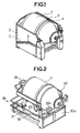
- la figure 2 représente une vue de côté, en perspective, d'une baratte montée sur un châssis tubulaire, selon l'invention,
- La figure 3 représente une vue de côté d'une baratte montée sur un châssis tubulaire, selon la figure 2,
- La figure 4 représente une vue en perspective, du châssis tubulaire selon les figures 2 et 3, dépourvu de baratte.
- FIG. 1 represents a side view, in perspective, of a churn mounted on a frame according to the prior art,
- FIG. 2 represents a side view, in perspective, of a churn mounted on a tubular chassis, according to the invention,
- FIG. 3 represents a side view of a churn mounted on a tubular frame, according to FIG. 2,
- 4 shows a perspective view of the tubular frame according to Figures 2 and 3, devoid of churn.
Les figures représentent, à la figure 1, une baratte 1, montée dans un châssis
2, réalisée en tôle pliée, constituant une sorte de caisson ouvert uniquement
sur le dessous, sur le dessus et sur l'avant, contre les côtés duquel sont fixés,
par des serre-fils 3, les câbles de liaison 4 et 5 des divers organes.The figures represent, in Figure 1, a
Les figures 2 et 3 représentent une baratte 1 montée sur un châssis 20
constitué principalement de plusieurs cadres tubulaires superposés 21, 22, 23
reliés verticalement par des montants 25, 26, sur l'avant duquel est disposé un
boítier de commande 30a et un coffre 30b renfermant les divers organes
d'entraínement et de contrôle de la baratte 1 tels que centrale hydraulique ou
pompe à vide, et sur l'arrière duquel est fixée une armoire électrique 31 de
puissance et de régulation. On remarquera que le cadre tubulaire 21
constituant la base du châssis tubulaire 20 est de plus forte section que les
autres 22, 23 et que le châssis 20 est renforcé par un tube raidisseur oblique
24, reliant l'un des angles du cadre tubulaire inférieur 21 au milieu du montant
25. On remarquera aussi que cette réalisation tubulaire du châssis 20 a été
mise à profit pour faire cheminer, à l'intérieur du tube raidisseur 24 et à
l'intérieur du côté arrière du dit cadre inférieur 21, les câbles électriques reliant
entre eux le boítier 30a, le coffre 30b et l'armoire électrique 31 sans que les dits
câbles électriques n'apparaissent à l'extérieur, car des tubes de raccordement
28, 29 cadre tubulaire 21 à l'armoire électrique 31 ont été prévus pour cela en
complément.Figures 2 and 3 show a
De même, les câbles électriques et/ou tubulures de fluide destinés à relier le
coffre 30b au moteur 33 passent à l'intérieur de conduits ménagés dans les
montants tubulaires 25, 26 ainsi que dans le berceau 32 de support de la
baratte. Les articulations entre les montants 25, 26 et le berceau 32 sont
prévues pour les passage de ces câbles et canalisations.Likewise, the electrical cables and / or fluid tubing intended to connect the
L'invention ne se limite bien évidemment pas au mode de réalisation donné ci-dessus comme exemple, car d'autres équipements, servant à la mise en fonction et au contrôle d'une enceinte rotative quelconque, peuvent être ainsi reliés avec les mêmes avantages, sans sortir du cadre de l'invention.The invention is obviously not limited to the embodiment given above as an example, because other equipment, used for setting function and control of any rotary enclosure, may be so related with the same advantages, without departing from the scope of the invention.
Claims (4)
Applications Claiming Priority (2)
| Application Number | Priority Date | Filing Date | Title |
|---|---|---|---|
| FR0110457 | 2001-08-03 | ||
| FR0110457A FR2828117A1 (en) | 2001-08-03 | 2001-08-03 | FIXED CHASSIS FOR SUPPORTING A ROTATING ENCLOSURE, ESPECIALLY A CHAMBER |
Publications (1)
| Publication Number | Publication Date |
|---|---|
| EP1281434A1 true EP1281434A1 (en) | 2003-02-05 |
Family
ID=8866284
Family Applications (1)
| Application Number | Title | Priority Date | Filing Date |
|---|---|---|---|
| EP02291908A Withdrawn EP1281434A1 (en) | 2001-08-03 | 2002-07-26 | Fixed support frame for rotary drum, in particular for churn |
Country Status (3)
| Country | Link |
|---|---|
| EP (1) | EP1281434A1 (en) |
| ES (1) | ES2189706T1 (en) |
| FR (1) | FR2828117A1 (en) |
Cited By (2)
| Publication number | Priority date | Publication date | Assignee | Title |
|---|---|---|---|---|
| EP1645190A1 (en) * | 2004-10-05 | 2006-04-12 | Inox Meccanica S.R.L. | Churn for processing food products |
| CN102318886A (en) * | 2011-08-02 | 2012-01-18 | 刘金波 | Tank type energy efficient total mixed ration feed mixer |
Citations (5)
| Publication number | Priority date | Publication date | Assignee | Title |
|---|---|---|---|---|
| EP0455611A1 (en) * | 1990-05-03 | 1991-11-06 | ALIMATIC S.r.l. | Automatic continuous operating system for massaging anatomically well defined salted meat pieces for making boiled hams, "coppas", bacons and the like |
| EP0600566A1 (en) * | 1992-12-04 | 1994-06-08 | Giovan Battista Possenti | Composite-movement machine for processing meat products |
| EP0643918A1 (en) * | 1993-09-13 | 1995-03-22 | Stork Protecon-Langen B.V. | Device for massaging a portion of meat |
| EP0765966A1 (en) * | 1995-09-29 | 1997-04-02 | Stork R.M.S. B.V. | Machine frame for the meat processing industry and tube profile |
| EP1082905A1 (en) * | 1998-06-05 | 2001-03-14 | Metalquimia, S.A. | Machine for the treatment of meat pieces |
-
2001
- 2001-08-03 FR FR0110457A patent/FR2828117A1/en active Pending
-
2002
- 2002-07-26 EP EP02291908A patent/EP1281434A1/en not_active Withdrawn
- 2002-07-26 ES ES02291908T patent/ES2189706T1/en active Pending
Patent Citations (5)
| Publication number | Priority date | Publication date | Assignee | Title |
|---|---|---|---|---|
| EP0455611A1 (en) * | 1990-05-03 | 1991-11-06 | ALIMATIC S.r.l. | Automatic continuous operating system for massaging anatomically well defined salted meat pieces for making boiled hams, "coppas", bacons and the like |
| EP0600566A1 (en) * | 1992-12-04 | 1994-06-08 | Giovan Battista Possenti | Composite-movement machine for processing meat products |
| EP0643918A1 (en) * | 1993-09-13 | 1995-03-22 | Stork Protecon-Langen B.V. | Device for massaging a portion of meat |
| EP0765966A1 (en) * | 1995-09-29 | 1997-04-02 | Stork R.M.S. B.V. | Machine frame for the meat processing industry and tube profile |
| EP1082905A1 (en) * | 1998-06-05 | 2001-03-14 | Metalquimia, S.A. | Machine for the treatment of meat pieces |
Cited By (3)
| Publication number | Priority date | Publication date | Assignee | Title |
|---|---|---|---|---|
| EP1645190A1 (en) * | 2004-10-05 | 2006-04-12 | Inox Meccanica S.R.L. | Churn for processing food products |
| CN102318886A (en) * | 2011-08-02 | 2012-01-18 | 刘金波 | Tank type energy efficient total mixed ration feed mixer |
| CN102318886B (en) * | 2011-08-02 | 2013-07-17 | 刘金波 | Tank type energy efficient total mixed ration feed mixer |
Also Published As
| Publication number | Publication date |
|---|---|
| ES2189706T1 (en) | 2003-07-16 |
| FR2828117A1 (en) | 2003-02-07 |
Similar Documents
| Publication | Publication Date | Title |
|---|---|---|
| CA2274950C (en) | Method and apparatus for supporting an element to be supported, in particular a patient's body with a support device independent of the control device | |
| FR2691037A1 (en) | Agricultural machine, particularly mower, with an improved load shedding and lifting device. | |
| FR2846016A1 (en) | Drilling unit for turning industrial machine e.g. back hoe, has connector inserted in between swing bracket and receptacle bracket, located on base periphery of internal hollow like arm | |
| EP2877094B1 (en) | Screen made of radiation shielding material for protecting an operator from ionising radiation | |
| EP1281434A1 (en) | Fixed support frame for rotary drum, in particular for churn | |
| FR2719752A1 (en) | Arrangement of a table with controlled mobile elements, in particular for people with reduced mobility. | |
| FR2661714A1 (en) | FUEL SUPPLY DEVICE FOR A GAS TURBINE. | |
| FR2785143A1 (en) | AGRICULTURAL MACHINE COMPRISING A DOUBLE CYLINDER WITH A SINGLE CYLINDER | |
| FR2649133A1 (en) | FRONT OPENING WASHING MACHINE | |
| EP0047685B1 (en) | Appliance door with a decorator panel | |
| EP0551234B1 (en) | Appliance, such as an electrical domestic appliance, fitted with a door with horizontal swinging axle and a device counterbalancing the door weight intended for being fitted with a trimpanel | |
| EP0579564B1 (en) | Mower intended to be connected to a motor vehicle and comprising an improved settlement device | |
| FR2499123A1 (en) | PIVOTING PITCHING PIT | |
| EP3370620B1 (en) | Radiation protection screen | |
| EP0570316A1 (en) | Agricultural implement, especially mower, with an improved power transmission device | |
| CA2005757A1 (en) | Mechanism for obtaining a translation motion in a marine environment and sonar equipped with said mechanism | |
| EP1082900A1 (en) | Tractor-mounted sprayer for spraying phytosanitary products | |
| FR2714367A1 (en) | Column crane. | |
| EP1227981A1 (en) | Aseptic packaging installation | |
| FR2722363A1 (en) | Agricultural machine for mowing and clearing soil | |
| EP1313386A1 (en) | Computer room desk | |
| FR2518225A1 (en) | MULTI-GAS COOKER | |
| US370228A (en) | Cooking attachment for ranges | |
| FR2469919A1 (en) | DENTIST'S ARMCHAIR | |
| FR2683435A1 (en) | Supporting arrangement for high units, as in a fitted kitchen |
Legal Events
| Date | Code | Title | Description |
|---|---|---|---|
| PUAI | Public reference made under article 153(3) epc to a published international application that has entered the european phase |
Free format text: ORIGINAL CODE: 0009012 |
|
| AK | Designated contracting states |
Designated state(s): AT BE BG CH CY CZ DE DK EE ES FI FR GB GR IE IT LI LU MC NL PT SE SK TR |
|
| AX | Request for extension of the european patent |
Extension state: AL LT LV MK RO SI |
|
| GBC | Gb: translation of claims filed (gb section 78(7)/1977) | ||
| 17P | Request for examination filed |
Effective date: 20030325 |
|
| AKX | Designation fees paid |
Designated state(s): AT BE BG CH CY CZ DE DK EE ES FI FR GB GR IE IT LI LU MC NL PT SE SK TR |
|
| STAA | Information on the status of an ep patent application or granted ep patent |
Free format text: STATUS: THE APPLICATION IS DEEMED TO BE WITHDRAWN |
|
| 18D | Application deemed to be withdrawn |
Effective date: 20060718 |