EP1281365A1 - Befestigungsvorrichtung - Google Patents
Befestigungsvorrichtung Download PDFInfo
- Publication number
- EP1281365A1 EP1281365A1 EP01118708A EP01118708A EP1281365A1 EP 1281365 A1 EP1281365 A1 EP 1281365A1 EP 01118708 A EP01118708 A EP 01118708A EP 01118708 A EP01118708 A EP 01118708A EP 1281365 A1 EP1281365 A1 EP 1281365A1
- Authority
- EP
- European Patent Office
- Prior art keywords
- fastening device
- fastening
- positioning
- securing element
- head
- Prior art date
- Legal status (The legal status is an assumption and is not a legal conclusion. Google has not performed a legal analysis and makes no representation as to the accuracy of the status listed.)
- Granted
Links
Images


Classifications
-
- A—HUMAN NECESSITIES
- A61—MEDICAL OR VETERINARY SCIENCE; HYGIENE
- A61B—DIAGNOSIS; SURGERY; IDENTIFICATION
- A61B17/00—Surgical instruments, devices or methods
- A61B17/56—Surgical instruments or methods for treatment of bones or joints; Devices specially adapted therefor
- A61B17/58—Surgical instruments or methods for treatment of bones or joints; Devices specially adapted therefor for osteosynthesis, e.g. bone plates, screws or setting implements
- A61B17/68—Internal fixation devices, including fasteners and spinal fixators, even if a part thereof projects from the skin
- A61B17/84—Fasteners therefor or fasteners being internal fixation devices
- A61B17/86—Pins or screws or threaded wires; nuts therefor
-
- F—MECHANICAL ENGINEERING; LIGHTING; HEATING; WEAPONS; BLASTING
- F16—ENGINEERING ELEMENTS AND UNITS; GENERAL MEASURES FOR PRODUCING AND MAINTAINING EFFECTIVE FUNCTIONING OF MACHINES OR INSTALLATIONS; THERMAL INSULATION IN GENERAL
- F16B—DEVICES FOR FASTENING OR SECURING CONSTRUCTIONAL ELEMENTS OR MACHINE PARTS TOGETHER, e.g. NAILS, BOLTS, CIRCLIPS, CLAMPS, CLIPS OR WEDGES; JOINTS OR JOINTING
- F16B23/00—Specially shaped nuts or heads of bolts or screws for rotations by a tool
- F16B23/0007—Specially shaped nuts or heads of bolts or screws for rotations by a tool characterised by the shape of the recess or the protrusion engaging the tool
- F16B23/0038—Specially shaped nuts or heads of bolts or screws for rotations by a tool characterised by the shape of the recess or the protrusion engaging the tool substantially prismatic with up to six edges, e.g. triangular, square, pentagonal, Allen-type cross-sections
-
- F—MECHANICAL ENGINEERING; LIGHTING; HEATING; WEAPONS; BLASTING
- F16—ENGINEERING ELEMENTS AND UNITS; GENERAL MEASURES FOR PRODUCING AND MAINTAINING EFFECTIVE FUNCTIONING OF MACHINES OR INSTALLATIONS; THERMAL INSULATION IN GENERAL
- F16B—DEVICES FOR FASTENING OR SECURING CONSTRUCTIONAL ELEMENTS OR MACHINE PARTS TOGETHER, e.g. NAILS, BOLTS, CIRCLIPS, CLAMPS, CLIPS OR WEDGES; JOINTS OR JOINTING
- F16B33/00—Features common to bolt and nut
- F16B33/02—Shape of thread; Special thread-forms
-
- F—MECHANICAL ENGINEERING; LIGHTING; HEATING; WEAPONS; BLASTING
- F16—ENGINEERING ELEMENTS AND UNITS; GENERAL MEASURES FOR PRODUCING AND MAINTAINING EFFECTIVE FUNCTIONING OF MACHINES OR INSTALLATIONS; THERMAL INSULATION IN GENERAL
- F16B—DEVICES FOR FASTENING OR SECURING CONSTRUCTIONAL ELEMENTS OR MACHINE PARTS TOGETHER, e.g. NAILS, BOLTS, CIRCLIPS, CLAMPS, CLIPS OR WEDGES; JOINTS OR JOINTING
- F16B35/00—Screw-bolts; Stay-bolts; Screw-threaded studs; Screws; Set screws
- F16B35/04—Screw-bolts; Stay-bolts; Screw-threaded studs; Screws; Set screws with specially-shaped head or shaft in order to fix the bolt on or in an object
- F16B35/041—Specially-shaped shafts
-
- F—MECHANICAL ENGINEERING; LIGHTING; HEATING; WEAPONS; BLASTING
- F16—ENGINEERING ELEMENTS AND UNITS; GENERAL MEASURES FOR PRODUCING AND MAINTAINING EFFECTIVE FUNCTIONING OF MACHINES OR INSTALLATIONS; THERMAL INSULATION IN GENERAL
- F16B—DEVICES FOR FASTENING OR SECURING CONSTRUCTIONAL ELEMENTS OR MACHINE PARTS TOGETHER, e.g. NAILS, BOLTS, CIRCLIPS, CLAMPS, CLIPS OR WEDGES; JOINTS OR JOINTING
- F16B39/00—Locking of screws, bolts or nuts
- F16B39/02—Locking of screws, bolts or nuts in which the locking takes place after screwing down
- F16B39/04—Locking of screws, bolts or nuts in which the locking takes place after screwing down with a member penetrating the screw-threaded surface of at least one part, e.g. a pin, a wedge, cotter-pin, screw
- F16B39/06—Locking of screws, bolts or nuts in which the locking takes place after screwing down with a member penetrating the screw-threaded surface of at least one part, e.g. a pin, a wedge, cotter-pin, screw with a pin or staple parallel to the bolt axis
-
- A—HUMAN NECESSITIES
- A61—MEDICAL OR VETERINARY SCIENCE; HYGIENE
- A61B—DIAGNOSIS; SURGERY; IDENTIFICATION
- A61B17/00—Surgical instruments, devices or methods
- A61B17/56—Surgical instruments or methods for treatment of bones or joints; Devices specially adapted therefor
- A61B17/58—Surgical instruments or methods for treatment of bones or joints; Devices specially adapted therefor for osteosynthesis, e.g. bone plates, screws or setting implements
- A61B17/68—Internal fixation devices, including fasteners and spinal fixators, even if a part thereof projects from the skin
- A61B17/84—Fasteners therefor or fasteners being internal fixation devices
- A61B17/86—Pins or screws or threaded wires; nuts therefor
- A61B2017/8655—Pins or screws or threaded wires; nuts therefor with special features for locking in the bone
-
- A—HUMAN NECESSITIES
- A61—MEDICAL OR VETERINARY SCIENCE; HYGIENE
- A61B—DIAGNOSIS; SURGERY; IDENTIFICATION
- A61B90/00—Instruments, implements or accessories specially adapted for surgery or diagnosis and not covered by any of the groups A61B1/00 - A61B50/00, e.g. for luxation treatment or for protecting wound edges
- A61B90/39—Markers, e.g. radio-opaque or breast lesions markers
- A61B2090/3983—Reference marker arrangements for use with image guided surgery
-
- A—HUMAN NECESSITIES
- A61—MEDICAL OR VETERINARY SCIENCE; HYGIENE
- A61B—DIAGNOSIS; SURGERY; IDENTIFICATION
- A61B34/00—Computer-aided surgery; Manipulators or robots specially adapted for use in surgery
- A61B34/20—Surgical navigation systems; Devices for tracking or guiding surgical instruments, e.g. for frameless stereotaxis
Definitions
- the present invention relates to a fastening device and a fastening system, in particular for attaching a positioning element, such as for example a marker, in a fixed defined relationship to an object such as a bone.
- a positioning element such as for example a marker
- the invention in a wide range of Surgery or general technique used, for example, in interventions in the field the hip, the spine or the head.
- the invention can be anywhere be used where it is required a particular element, such as a Markers, as fixed as possible and against twisting or displacement on an object, such as Example to attach a bone or a bone structure.
- the fastening device according to the invention has at least one guide for a securing element on. Through this guide can before, after or simultaneously with the introduction the fastening device in, for example, a bone a securing element in the Bone be introduced to the introduced fastening device by further Inserting the fuse element against unwanted movement, such as to secure a slight twisting.
- the fastening device is elongated and approximately cylindrical in shape and preferably has a shaft, wherein a part of the shaft is preferably suitable to be introduced into a bone.
- a head is preferably provided which is suitably formed may be, for example, a tool for introducing the fastening device to attach and / or at least one positioning element as possible as possible to it Fasten.
- the shaft has an engagement region at an outer end and an intermediate region on which between the engagement region and the head of the fastening device is arranged.
- the engagement region is preferably designed such that an introduction the fastening device is made possible in an object, such as a bone, wherein after insertion also a stable as possible attachment through the engagement area should be made sure.
- the diameter of the intermediate region is greater than the diameter of the engagement region, but also formed both areas with approximately the same diameter or the engagement area may be smaller in diameter than the intermediate area can have.
- the transition between engagement area and intermediate area Conveniently tapered to provide a sharp transition between engagement area and intermediate area to avoid.
- the fastening device for Example be introduced so far into an object, until due to the larger diameter the intermediate region prevents further introduction of the fastening device or is difficult.
- the guide according to the invention is advantageously designed as a bore and / or as a recess.
- the guide as a combination of a bore or a Through hole of a head or shaft area exist, with other shaft portions may have a recess or a further bore or no guide.
- the guide is advantageously designed so that it is approximately in the longitudinal direction of the fastening device runs, preferably parallel to it and advantageously with a small lateral Offset of, for example, 0.1 to 10 mm to the central axis of the engagement area.
- the fastening device has at least one bore, by which a securing element can be performed and held, wherein if for example, the bore is arranged in the intermediate region of the shaft and the distance between the central axis of the bore and central axis of the engagement region is smaller than that Diameter of the engagement area, advantageously a semicircular or round recess in the Engagement area is provided to the securing element along the engagement area to to lead.
- the guide for the securing element can both be designed in this way be that the outer circumference of the guide or a then introduced security element overlaps with the outer periphery of the engagement portion, so that the securing element is preferably guided along the engagement region and in the vicinity or adjacent to the engagement area is introduced.
- the guide can also be designed in that a securing element to be introduced and the shank or engagement region of the fastening device do not lie directly against each other, but a distance for example in the range of 0.1 to 10 mm from each other, the securing element being e.g. is guided through a bore of the head or a shaft area ..
- more than one guide so for example 2, 3, 4 to 10 or more guides be provided on the fastening device to a plurality of securing elements to contribute.
- the guides can be both parallel to each other and to a Be formed central axis of the engagement portion. It is also possible to arrange the guides that fuse elements at a certain angle to each other and possibly also be introduced to a central axis of the engagement portion in the fastening device can, for example, a more stable attachment or securing the fastening device to achieve.
- the fastening device according to the invention formed as a screw and has in the engagement area a thread, wherein in the engagement area Through the thread passing through a guide hole can be provided. It may alternatively or in addition to a guide hole for a securing element a lateral Be provided recess in the engagement region, so that the screw thread at a or more places is interrupted to one or more fuse elements along the To bring intervention area.
- the engagement region can also be formed as a nail, wherein also at least one Leadership can be provided in the Eingniff Scheme.
- the outer surface of the engagement area be substantially flat, for example, along the direction of insertion a or more edges may be provided to the introduction of the fastening device to facilitate and prevent subsequent unintentional twisting or prevent.
- a tapering region is formed at the outer end of the introduction region, for example in the form of a small cone or a pyramid with one or more lateral edges to facilitate the attachment and insertion of the fastening device.
- a connecting element such as a protrusion or depression, for example, an insertion opening provided, for example, a tool for introducing the fastening device to be able to apply and / or a positioning element or other desired To connect objects as possible against rotation with the fastening device.
- a projection and / or an insertion opening is preferably not rotationally symmetrical formed and may have one or more edges, so that, for example, an Allen key can be used in the head of the fastening device to this in a Screw in the bone and then turn against the fastening device
- Positioning element such as a reference star, can be attached to it, after a securing element has been introduced.
- several can on the head Recesses may be provided to a positioning member to be mounted in a Variety of angular positions against rotation on the fastening device to bring to be able to.
- a fastening system which consists of the fastening device described above, wherein at least one Secured element introduced into the at least one guide of the fastening device is.
- the securing element may be formed, for example, as a screw and has advantageous a cylindrical elongated shape, wherein the outer diameter of the securing element is preferably formed so that the securing element with only a small or can be performed without play by the leadership of the fastening device.
- the Securing element can as well as the fastening device described above a Head and a shaft which, for example, again in engagement area and Intermediate area is divided. With respect to possible embodiments of the shaft and / or Head is made to the features described above for the fastening device, which may also be formed in the securing element.
- the diameter of the securing element is smaller than the diameter of the fastening device, in particular, smaller than the diameter of the engaging portion thereof.
- a positioning system which consists of the fastening system described above and continue to one fixed positioning element, such as at least one marker or a Reference star with three Markem or holding devices for the corresponding marker has.
- the positioning system is designed so that the on the fastening system attached positioning element can be adjusted, for example by at least one Axis can be rotated so that the best possible alignment of the positioning element can be adjusted.
- the positioning element preferably in be locked in the set position, so that inadvertent tilting or pivoting of the positioning element relative to the fastening system substantially is prevented.
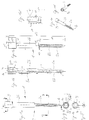
- FIG. 1a shows a top view of a fastening device 1, which consists of a shaft 2 and a head 3 composed.
- the shaft 2 has a trained as a screw engaging portion 2a and an intermediate portion 2d, which has a larger outer diameter as the engagement portion 2a has.
- the transition regions between engagement region 2a, intermediate region 2b and head 3 are conically formed as a cone portion, so that the respective Divide areas without sharp edges into each other.
- a tip 4 is formed, which has a plurality of lateral edges, as shown in FIG le recognizable. The tip 4 simplifies the attachment and insertion of the fastening device 1.
- Figure 1b shows a cross section of the fastening device shown in Figure 1 along the Line A-A.
- the guide serving as a guide for a fuse element bore 5a in the Between the region 2b and the head 3 can be seen, the guide, as indicated by the dot-dash line Line indicated, outside the through hole 5a in the region of the engagement region 2a is formed as a groove or recess 5b, so that a securing element by the head 3 and the intermediate region 2b are guided along the engagement region 2a can be and so for example after penetration of the fastening device, for example in a bone approximately parallel to the direction of penetration of the fastening device through the Guide 5a, 5b can also be introduced into the bone, so as to prevent rotation to obtain the fastening device.
- the head 3 also has one in the perspective view of Figure 1f and the plan view 1g recognizable recess 3a, which in cross section in approximately a uniform Hexagon forms, for example, to attach an Allen key or a slip-on can.
- the recess 3a is formed approximately semicircular to the introduction to allow a securing element in the guide hole 5a, as shown in Figure 3a shown.
- FIG. 1c shows the fastening device 1 shown in FIG. 1a and rotated through 180 ° the groove or guide recess 5b running in the engagement region 2a can be seen, which interrupts the thread of the screw so that a fuse element parallel can be guided to the screw.
- Figure 1d shows the in Figure 1b marked section X of the threaded engagement area 2a.
- the distance of a thread too a lying in the cutting plane inner region of the screw d9 is 3.6 mm.
- FIG. 1h shows a sectional view along the line B-B of the fastening device shown in FIG. 1a.
- the outer circumference of the recess can also be seen 3a designed so that on the one hand by serving as a guide through hole 5a a securing element can be introduced and then after insertion of the fuse element through the multi-edge recess 3a an essay on the fastening device 1 can be placed against rotation.
- FIG. 1 a shows a cross section along the line C - C of the engagement region shown in FIG 2a.
- FIGS 2a to 2d show an embodiment of a securing element 6, which used together with the fastening device 1 according to the invention shown in FIG can be.
- the securing element 6 has a shaft 7 and a head 8.
- the shaft 7 is divided into a screw-threaded engagement region 7 a, at the lower end of a tip 9 is provided and at the opposite end of the tip 9 End adjacent to the intermediate region 7b, which between the engagement region 7a and the head 8 is located.
- the head 8 in turn has a recess 8a, which is formed in the form of a hexagon, as shown in the plan view of Figure 2d, to the Example, an Allen key to the head 8 of the fuse element 6 to set the Securing element 6 through the guide 5 of the example screwed into a bone Screw fastening device 1 and so as for example in the cross-sectional view 3a to prevent twisting of the fastening device 1.
- a recess 8a which is formed in the form of a hexagon, as shown in the plan view of Figure 2d, to the Example, an Allen key to the head 8 of the fuse element 6 to set the Securing element 6 through the guide 5 of the example screwed into a bone Screw fastening device 1 and so as for example in the cross-sectional view 3a to prevent twisting of the fastening device 1.
- at the embodiment shown is achieved in general an anti-rotation, that after introducing the securing element 6 in the fastening device 1, the side by side lying engagement portions 2a and 7a is no longer rotationally
- the specified dimensions are to be regarded as exemplary embodiments only and should clarify that with the device according to the invention only a relatively small surgical Intervention is required. It is possible that the fastening device 1 and the Fuse element 6 have approximately the same length and with respect to the engagement areas 2a, 7a and intermediate regions 2b and 7b have approximately similar dimensions. however can also be a longer or shorter fuse element with a longer or shorter Engagement area 7a and / or intermediate area 7b are used. Generally, it is beneficial if the securing element is designed so that the total length including the Head 8 is smaller than the total length of the fastening device 1, so that when the Safety element 6 no longer protrudes from the head 3, in particular completely in the Fastening device 1 is introduced, i.
- the head 8 of the securing element 6 in the lower region of the head 3 of the fastening device 1 can be sunk, leaving the full recess 3a of the head 3 can be used for introducing, for example, a reference star, without the Head 8 of the introduced securing element 6 projects into the recess 3a.
- FIG. 2c shows an enlargement of the engagement region 7a marked X in FIG. 2b.
- Figures 3a to 3d show a positioning system according to the invention, wherein the in Figure 2 shown fuse element 6 inserted into the fastening device shown in Figure 1 is.
- Figure 3c shows a top view of a positioning system, wherein on the fastening system 1, 6 serving as a positioning element reference star 11 is placed on the Holding devices 11a, 11b and 11c each marker can be plugged. Of the Reference star 11 is attached to the mounting system by means of an adjustable alignment device 10 1, 6 attached.
- FIG. 3b shows the positioning system shown in FIG. 3c in a perspective view.
- the alignment device 10 has a screw 10 a, which for attachment to the Fixing system 1, 6 and / or for rotation of the attached reference star 11 um the longitudinal axis of the fastening device 1 can be used.
- the reference star 11 can be rotated about an axis which is approximately perpendicular to the central axis of the fastening device 1 is. This can be done using the alignment device 10 of the reference star 11 at one, for example, in a bone mounted fastening system 1, 6 and attached for a good detection of the reference star 11 applied markers (not shown) are positioned.
- FIG. 3a shows a sectional view along the line A-A of the positioning system shown in FIG. 3c. It can be seen that in the inserted state of the securing element 6 in the fastening device 1, the engaging portions 2a, 7a and the intermediate regions 2b, 7b in lie next to each other.
- the alignment device 10 is in the recess 3a of the fastening device used and attached to it. By protrusions and / or depressions on the underside of the alignment device 10, which in the projections or depressions 3b engage on the top of the fastening device 1, can be a rotation between alignment device 10 with attached reference star 11 and the fastening system 1, 6 can be achieved.
- the present invention thus enables the relatively simple introduction of a non-rotating Fastening device, for example, in a bone using for example, only two parts, the fastening device and at least one securing element. This reduces the production costs for such a fastening system. Furthermore, the cleaning of such a fastening system is due to the use from e.g. only two parts relatively easy.
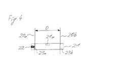
- Figure 4 shows a fastening system according to an alternative aspect of the present invention.
- a positioning element such as that shown in FIG Reference star 11 on an element, such as a bone
- Kirschner wires or Schanz screws 20a, 20b are used, which are known Way into a bone.
- the distance D therebetween can for Example 0.1 to 100 mm, preferably 0.1 to 10 mm.
- a fastening device 11 is guided or attached, which has through holes 23a, 23b for the wires or screws 20a, 20b.
- one or more locking elements 22 which can be moved, for example, a non-positive connection with one or more Kirschner wires or Schanz screws manufacture, the fastening device 21 against rotation on the wires or screws 20a, 20b are attached.
- a locking member 22 positioned, so can protruding wires or screws are cut off and to the fastening device 21 may be a positioning element are inserted, inserted into a recess 21a and, for example by means of appropriate Screws are attached.
- the fastening device 21 may be stationary and rotationally secured to an element, such as a bone.
Landscapes
- Engineering & Computer Science (AREA)
- General Engineering & Computer Science (AREA)
- Health & Medical Sciences (AREA)
- Mechanical Engineering (AREA)
- Orthopedic Medicine & Surgery (AREA)
- Surgery (AREA)
- Life Sciences & Earth Sciences (AREA)
- Heart & Thoracic Surgery (AREA)
- General Health & Medical Sciences (AREA)
- Biomedical Technology (AREA)
- Neurology (AREA)
- Medical Informatics (AREA)
- Molecular Biology (AREA)
- Animal Behavior & Ethology (AREA)
- Nuclear Medicine, Radiotherapy & Molecular Imaging (AREA)
- Public Health (AREA)
- Veterinary Medicine (AREA)
- Surgical Instruments (AREA)
- Basic Packing Technique (AREA)
- Seal Device For Vehicle (AREA)
- Paper (AREA)
- Connection Of Plates (AREA)
- Insertion Pins And Rivets (AREA)
Abstract
Description
- Figuren 1a bis 1i
- eine erfindungsgemäße Ausführungsform einer Befestigungsvorrichtung mit einer Führung;
- Figuren 2a bis 2d
- eine Ausführungsform eines Sicherungselements, welches in die Befestigungsvorrichtung von Figur 1 eingebracht werden kann;
- Figuren 3a bis 3c
- ein erfindungsgemäßes Positionierungssystem; und
- Figur 4
- eine alternative Ausführungsform einer erfindungsgemäßen Befestigungsvorrichtung.
Claims (21)
- Befestigungsvorrichtung mit mindestens einer Führung (5a, 5b) für mindestens ein Sicherungselement (6).
- Befestigungsvorrichtung nach Anspruch 1, wobei die Befestigungsvorrichtung einen Schaft (2) und einen Kopf (3) aufweist.
- Befestigungsvorrichtung nach Anspruch 2, wobei der Schaft (2) einen Eingriffbereich (2a) und einen Zwischenbereich (2b) aufweist.
- Befestigungsvorrichtung nach Anspruch 3, wobei der Durchmesser des Zwischenbereiches (2b) größer als der Durchmesser des Eingriffbereiches (2a) ist.
- Befestigungsvorrichtung nach einem der vorhergehenden Ansprüche, wobei die Führung als Bohrung (5a) und/oder als Ausnehmung (5b) ausgebildet ist.
- Vorrichtung nach einem der vorhergehenden Ansprüche, wobei zwei, drei oder mehr Führungen (5) in der Befestigungsvorrichtung ausgebildet sind.
- Befestigungsvorrichtung nach einem der vorhergehenden Ansprüche, wobei die Befestigungsvorrichtung einen mit einem Gewinde versehenen Bereich aufweist.
- Befestigungsvorrichtung nach einem der vorhergehenden Ansprüche, wobei die Befestigungsvorrichtung einen als Nagel ausgebildeten Bereich und/oder einen Bereich mit in etwa parallel zur Einbringrichtung verlaufenden Kanten aufweist.
- Befestigungsvorrichtung nach einem der vorhergehenden Ansprüche, wobei die Befestigungsvorrichtung ein spitz zulaufendes Element (4) am unteren Ende aufweist.
- Befestigungsvorrichtung nach einem der vorhergehenden Ansprüche, wobei die Befestigungsvorrichtung ein Verbindungselement oder eine Vertiefung (3a) aufweist, bei welcher Werkzeuge angesetzt oder Vorrichtungen (10, 11) angebracht werden können.
- Befestigungssystem mit einer Befestigungsvorrichtung (1) nach einem der Ansprüche 1 bis 10 und mindestens einem Sicherungselement (6), welches zumindest teilweise in die Führung (5a, 5b) eingesetzt ist.
- Befestigungssystem nach Anspruch 11, wobei das Sicherungselement (6) einen Bereich (7a) aufweist, welcher mit einem Gewinde versehen ist und/oder einen Bereich (7b) aufweist, welcher eine im wesentlichen glatte Oberfläche aufweist und/oder einen Kopf (8) aufweist.
- Befestigungsvorrichtung nach Anspruch 11 oder 12, wobei die Führung (5a, 5d) der Befestigungsvorrichtung (1) und das Sicherungselement (6) so ausgebildet sind, dass das in die Befestigungsvorrichtung (1) eingesetzte Sicherungselement (6) im wesentlichen kein Spiel aufweist.
- Positionierungssystem mit einem Befestigungssystem (1, 6) nach einem der Ansprüche 11 bis 13 und einem daran befestigten Positionierungselement (11).
- Positionierungssystem nach Anspruch 14, wobei das Positionierungselement (11) mittels einer verstellbaren Ausrichtungsvorrichtung (10) an dem Befestigungssystem (1, 6) befestigt ist.
- Positionierungssystem nach einem der Ansprüche 14 oder 15, wobei das Positionierungselement ein Referenzstern (11) ist.
- Befestigungsvorrichtung mit mindestens zwei Führungen (23a, 23b).
- Befestigungsvorrichtung nach Anspruch 17, wobei mindestens ein Feststellelement (22) zum Herstellen eines Kraftschlusses zwischen mindestens einem in einer der Führungen (23a, 23b) geführten Elemente vorgesehen ist.
- Befestigungsvorrichtung nach einem der Ansprüche 17 oder 18, wobei mindestens ein Befestigungsbereich, insbesondere eine Vertiefung (21a) in der Befestigungsvorrichtung (21), insbesondere zum Anbringen eines Positionierungselements (11) vorgesehen ist.
- Befestigungssystem mit einer Befestigungsvorrichtung nach einem der Ansprüche 17 bis 19 und in den Führungen (23a, 23b) geführten Elementen, insbesondere Kirschnerdrähten oder Schanzschrauben.
- Positionierungssystem mit einem Befestigungssystem nach Anspruch 20 und einem daran befestigten Positionierungselement (11) und/oder einer verstellbaren Ausrichtungsvorrichtung (10).
Priority Applications (5)
| Application Number | Priority Date | Filing Date | Title |
|---|---|---|---|
| AT01118708T ATE321498T1 (de) | 2001-08-03 | 2001-08-03 | Befestigungsvorrichtung |
| DE50109353T DE50109353D1 (de) | 2001-08-03 | 2001-08-03 | Befestigungsvorrichtung |
| EP01118708A EP1281365B1 (de) | 2001-08-03 | 2001-08-03 | Befestigungsvorrichtung |
| US10/001,952 US20030078565A1 (en) | 2001-08-03 | 2001-10-31 | Fixing device |
| US11/681,385 US7862568B2 (en) | 2001-08-03 | 2007-03-02 | Fixing device |
Applications Claiming Priority (1)
| Application Number | Priority Date | Filing Date | Title |
|---|---|---|---|
| EP01118708A EP1281365B1 (de) | 2001-08-03 | 2001-08-03 | Befestigungsvorrichtung |
Publications (2)
| Publication Number | Publication Date |
|---|---|
| EP1281365A1 true EP1281365A1 (de) | 2003-02-05 |
| EP1281365B1 EP1281365B1 (de) | 2006-03-29 |
Family
ID=8178228
Family Applications (1)
| Application Number | Title | Priority Date | Filing Date |
|---|---|---|---|
| EP01118708A Expired - Lifetime EP1281365B1 (de) | 2001-08-03 | 2001-08-03 | Befestigungsvorrichtung |
Country Status (4)
| Country | Link |
|---|---|
| US (2) | US20030078565A1 (de) |
| EP (1) | EP1281365B1 (de) |
| AT (1) | ATE321498T1 (de) |
| DE (1) | DE50109353D1 (de) |
Cited By (11)
| Publication number | Priority date | Publication date | Assignee | Title |
|---|---|---|---|---|
| WO2004078049A1 (de) | 2003-03-07 | 2004-09-16 | Synthes Ag Chur | Verriegelungsschraube für marknagel |
| EP1642546A1 (de) | 2004-09-30 | 2006-04-05 | DePuy Products, Inc. | Gerät zur Durchführung eines orthopädischen Eingriffs |
| WO2006055448A1 (en) * | 2004-11-16 | 2006-05-26 | Innovative Spinal Technologies | Off-axis anchor guidance system |
| US7588588B2 (en) | 2003-10-21 | 2009-09-15 | Innovative Spinal Technologies | System and method for stabilizing of internal structures |
| US7588575B2 (en) | 2003-10-21 | 2009-09-15 | Innovative Spinal Technologies | Extension for use with stabilization systems for internal structures |
| US7967826B2 (en) | 2003-10-21 | 2011-06-28 | Theken Spine, Llc | Connector transfer tool for internal structure stabilization systems |
| WO2016134911A1 (de) * | 2015-02-26 | 2016-09-01 | Aesculap Ag | Medizinisches instrumentarium und verfahren |
| US10702343B2 (en) | 2015-02-26 | 2020-07-07 | Aesculap Ag | Medical instrumentation including a navigation system |
| US10905489B2 (en) | 2017-09-25 | 2021-02-02 | Aesculap Ag | Medical deformation device, deformation system and method for deforming an article |
| US10980578B2 (en) | 2016-08-23 | 2021-04-20 | Aesculap Ag | Medical instrumentation and method |
| WO2025003070A1 (en) * | 2023-06-26 | 2025-01-02 | Naviswiss Ag | Attachment device for attaching a navigation aid to a bone |
Families Citing this family (23)
| Publication number | Priority date | Publication date | Assignee | Title |
|---|---|---|---|---|
| US8052695B2 (en) * | 2002-10-11 | 2011-11-08 | Ge Medical Systems Global Technology Company Llc | Adjustable instruments for use with an electromagnetic localizer |
| US7753910B2 (en) * | 2003-07-21 | 2010-07-13 | Stephen Ritland | Surgical image tracker mounting base apparatus and method of use |
| FR2871362B1 (fr) * | 2004-06-11 | 2007-05-25 | Michel Allard | Broche de fixation d'un support sur un os |
| US8192449B2 (en) * | 2005-10-25 | 2012-06-05 | Brainlab Ag | Non-penetrating fixing device |
| EP1779799B1 (de) * | 2005-10-27 | 2008-12-17 | BrainLAB AG | Vorrichtung zur Befestigung eines Referenzelementes |
| DE502006003271D1 (de) * | 2006-08-18 | 2009-05-07 | Brainlab Ag | Adapter zur Anbringung einer Referenzanordnung an ein medizinisches Instrument, das eine funktionale Richtung bzw. Ebene aufweist |
| US20080161824A1 (en) * | 2006-12-27 | 2008-07-03 | Howmedica Osteonics Corp. | System and method for performing femoral sizing through navigation |
| US11116576B2 (en) * | 2012-06-21 | 2021-09-14 | Globus Medical Inc. | Dynamic reference arrays and methods of use |
| CN105073054B (zh) | 2013-01-16 | 2018-07-10 | 史赛克公司 | 指示视线误差的导航系统和方法 |
| US9993273B2 (en) | 2013-01-16 | 2018-06-12 | Mako Surgical Corp. | Bone plate and tracking device using a bone plate for attaching to a patient's anatomy |
| US9161799B2 (en) | 2013-01-28 | 2015-10-20 | Warsaw Orthopedic, Inc. | Surgical implant system and method |
| US20150282735A1 (en) * | 2014-04-04 | 2015-10-08 | Izi Medical Products,Llc | Reference device for surgical navigation system |
| US10537395B2 (en) | 2016-05-26 | 2020-01-21 | MAKO Surgical Group | Navigation tracker with kinematic connector assembly |
| US20200205870A1 (en) * | 2017-09-08 | 2020-07-02 | Device Synergies, PTY LTD | Cannulated fixation device |
| US10731687B2 (en) | 2017-11-22 | 2020-08-04 | Medos International Sarl | Instrument coupling interfaces and related methods |
| US11464577B2 (en) | 2018-03-02 | 2022-10-11 | Mako Surgical Corp. | Tool assembly, systems, and methods for manipulating tissue |
| US11819287B2 (en) | 2018-12-17 | 2023-11-21 | Zimmer Biomet Spine, Inc. | Universal navigation instrument adapter |
| WO2021007803A1 (zh) * | 2019-07-17 | 2021-01-21 | 杭州三坛医疗科技有限公司 | 骨折复位闭合手术定位导航方法和用于该方法的定位装置 |
| US11644053B2 (en) | 2019-11-26 | 2023-05-09 | Medos International Sarl | Instrument coupling interfaces and related methods |
| US12533207B2 (en) | 2020-09-22 | 2026-01-27 | Mobius Imaging, Llc | Mount assemblies for use with navigated surgical systems |
| US20230030567A1 (en) * | 2021-07-29 | 2023-02-02 | Ming-Cheng Pai | Screw member |
| CN114224482A (zh) * | 2021-11-04 | 2022-03-25 | 上海由格医疗技术有限公司 | 基于关键点跟踪的定位方法、系统、设备、终端及应用 |
| CN115517763A (zh) * | 2022-08-11 | 2022-12-27 | 苏州微创畅行机器人有限公司 | 光学定位装置及手术机器人 |
Citations (7)
| Publication number | Priority date | Publication date | Assignee | Title |
|---|---|---|---|---|
| US1495687A (en) * | 1922-10-19 | 1924-05-27 | Grosclaude Daniel | Manufacturing process for bolts with lockable nuts |
| US1829293A (en) * | 1929-05-17 | 1931-10-27 | Shakeproof Lock Washer Co | Screw lock |
| US2367399A (en) * | 1942-09-21 | 1945-01-16 | Isakson Stig | Lock nut |
| US4754749A (en) * | 1986-04-29 | 1988-07-05 | Tsou Paul M | Surgical screw with counter-rotation prevention means |
| US6048151A (en) * | 1999-04-16 | 2000-04-11 | Kwee; Kim | Threaded fastener |
| WO2000066045A1 (en) * | 1999-05-05 | 2000-11-09 | Michelson Gary K | Spinal fusion implants with opposed locking screws |
| US6203543B1 (en) * | 1999-06-21 | 2001-03-20 | Neil David Glossop | Device for releasably securing objects to bones |
Family Cites Families (16)
| Publication number | Priority date | Publication date | Assignee | Title |
|---|---|---|---|---|
| US159306A (en) * | 1875-02-02 | Improvement in nut-locks | ||
| US216222A (en) * | 1879-06-03 | Improvement in nut-locks | ||
| US1000280A (en) * | 1910-06-20 | 1911-08-08 | R De Witt Burdick | Wood-screw. |
| US1201864A (en) * | 1915-07-06 | 1916-10-17 | George William Overmeyer | Surgical appliance. |
| US1909476A (en) * | 1931-11-28 | 1933-05-16 | Shakeproof Lock Washer Co | Self-tapping screw |
| US2143922A (en) * | 1936-09-16 | 1939-01-17 | Harry Herschel Leiter | Bone surgery appliance |
| US2400348A (en) * | 1943-05-15 | 1946-05-14 | Whitney E Greene | Anchorage insert for screwthreaded fastenings |
| US5733289A (en) * | 1992-10-27 | 1998-03-31 | Neoligaments Limited | Ligament graft harvesting |
| FR2724553B1 (fr) * | 1994-09-15 | 1996-12-20 | Tornier Sa | Fixateur externe ou interne destine a la reparation des fractures ou des arthroplasties du squelette |
| US5976139A (en) * | 1996-07-17 | 1999-11-02 | Bramlet; Dale G. | Surgical fastener assembly |
| US6021343A (en) * | 1997-11-20 | 2000-02-01 | Surgical Navigation Technologies | Image guided awl/tap/screwdriver |
| US6033407A (en) * | 1998-01-27 | 2000-03-07 | Behrens; Alfred F. | Apparatus and method for intramedullary nailing and intramedullary nail therefor |
| DE20103416U1 (de) * | 2001-02-06 | 2001-07-05 | BrainLAB AG, 85551 Kirchheim | Vorrichtung zum Anbringen eines Elementes an einem Körper |
| US6719757B2 (en) * | 2001-02-06 | 2004-04-13 | Brainlab Ag | Device for attaching an element to a body |
| US6711431B2 (en) * | 2002-02-13 | 2004-03-23 | Kinamed, Inc. | Non-imaging, computer assisted navigation system for hip replacement surgery |
| US6856828B2 (en) * | 2002-10-04 | 2005-02-15 | Orthosoft Inc. | CAS bone reference and less invasive installation method thereof |
-
2001
- 2001-08-03 AT AT01118708T patent/ATE321498T1/de not_active IP Right Cessation
- 2001-08-03 EP EP01118708A patent/EP1281365B1/de not_active Expired - Lifetime
- 2001-08-03 DE DE50109353T patent/DE50109353D1/de not_active Expired - Lifetime
- 2001-10-31 US US10/001,952 patent/US20030078565A1/en not_active Abandoned
-
2007
- 2007-03-02 US US11/681,385 patent/US7862568B2/en not_active Expired - Fee Related
Patent Citations (7)
| Publication number | Priority date | Publication date | Assignee | Title |
|---|---|---|---|---|
| US1495687A (en) * | 1922-10-19 | 1924-05-27 | Grosclaude Daniel | Manufacturing process for bolts with lockable nuts |
| US1829293A (en) * | 1929-05-17 | 1931-10-27 | Shakeproof Lock Washer Co | Screw lock |
| US2367399A (en) * | 1942-09-21 | 1945-01-16 | Isakson Stig | Lock nut |
| US4754749A (en) * | 1986-04-29 | 1988-07-05 | Tsou Paul M | Surgical screw with counter-rotation prevention means |
| US6048151A (en) * | 1999-04-16 | 2000-04-11 | Kwee; Kim | Threaded fastener |
| WO2000066045A1 (en) * | 1999-05-05 | 2000-11-09 | Michelson Gary K | Spinal fusion implants with opposed locking screws |
| US6203543B1 (en) * | 1999-06-21 | 2001-03-20 | Neil David Glossop | Device for releasably securing objects to bones |
Cited By (18)
| Publication number | Priority date | Publication date | Assignee | Title |
|---|---|---|---|---|
| EP2263584A3 (de) * | 2003-03-07 | 2011-04-27 | Synthes GmbH | Verriegelungsschraube für Marknagel |
| US8888779B2 (en) | 2003-03-07 | 2014-11-18 | DePuy Synthes Products, LLC | Locking screw for an intramedullary nail |
| EP1601297B1 (de) * | 2003-03-07 | 2013-07-17 | Synthes GmbH | Verriegelungsschraube für marknagel |
| WO2004078049A1 (de) | 2003-03-07 | 2004-09-16 | Synthes Ag Chur | Verriegelungsschraube für marknagel |
| US7967826B2 (en) | 2003-10-21 | 2011-06-28 | Theken Spine, Llc | Connector transfer tool for internal structure stabilization systems |
| US7618442B2 (en) | 2003-10-21 | 2009-11-17 | Theken Spine, Llc | Implant assembly and method for use in an internal structure stabilization system |
| US7905907B2 (en) | 2003-10-21 | 2011-03-15 | Theken Spine, Llc | Internal structure stabilization system for spanning three or more structures |
| US7588575B2 (en) | 2003-10-21 | 2009-09-15 | Innovative Spinal Technologies | Extension for use with stabilization systems for internal structures |
| US7588588B2 (en) | 2003-10-21 | 2009-09-15 | Innovative Spinal Technologies | System and method for stabilizing of internal structures |
| EP1642546A1 (de) | 2004-09-30 | 2006-04-05 | DePuy Products, Inc. | Gerät zur Durchführung eines orthopädischen Eingriffs |
| US8361128B2 (en) | 2004-09-30 | 2013-01-29 | Depuy Products, Inc. | Method and apparatus for performing a computer-assisted orthopaedic procedure |
| WO2006055448A1 (en) * | 2004-11-16 | 2006-05-26 | Innovative Spinal Technologies | Off-axis anchor guidance system |
| WO2016134911A1 (de) * | 2015-02-26 | 2016-09-01 | Aesculap Ag | Medizinisches instrumentarium und verfahren |
| US10702343B2 (en) | 2015-02-26 | 2020-07-07 | Aesculap Ag | Medical instrumentation including a navigation system |
| US10786287B2 (en) | 2015-02-26 | 2020-09-29 | Aesculap | Medical instrumentation and method |
| US10980578B2 (en) | 2016-08-23 | 2021-04-20 | Aesculap Ag | Medical instrumentation and method |
| US10905489B2 (en) | 2017-09-25 | 2021-02-02 | Aesculap Ag | Medical deformation device, deformation system and method for deforming an article |
| WO2025003070A1 (en) * | 2023-06-26 | 2025-01-02 | Naviswiss Ag | Attachment device for attaching a navigation aid to a bone |
Also Published As
| Publication number | Publication date |
|---|---|
| ATE321498T1 (de) | 2006-04-15 |
| US7862568B2 (en) | 2011-01-04 |
| DE50109353D1 (de) | 2006-05-18 |
| US20030078565A1 (en) | 2003-04-24 |
| US20070160439A1 (en) | 2007-07-12 |
| EP1281365B1 (de) | 2006-03-29 |
Similar Documents
| Publication | Publication Date | Title |
|---|---|---|
| EP1281365B1 (de) | Befestigungsvorrichtung | |
| DE60119890T2 (de) | Handfixierungsvorrichtung | |
| DE60216667T2 (de) | Vorrichtung zur Positionierung der Schnittebene einer Knochensägenführung | |
| DE69514257T2 (de) | Implantat für die Behandlung von Frakturen des Femur | |
| EP1486175B1 (de) | Osteosyntheseplatte oder vergleichbares Implantat nebst Kugelhülse | |
| DE102007028087B4 (de) | Modularer Implantatteil und Kniegelenkprothese | |
| DE602004006471T2 (de) | Metatarsalphalangeale Vollprothese und Hilfsgerät zum Einsetzen einer solchen Prothese. | |
| DE69817341T2 (de) | System für die vorder-verplattung der halswirbelsäule | |
| EP1677693B1 (de) | Knochenplatte | |
| EP1024762B1 (de) | Knochenfixationsvorrichtung | |
| EP0291632A1 (de) | Kleinknochenplatte, insbesondere für die Versorgung von Frakturen des Schädel- und Gesichtsskeletts oder dergleichen | |
| DE3541597A1 (de) | Einrichtung zur behandlung eines knochens | |
| DE9115200U1 (de) | Verriegelungsnagel für die Versorgung von Frakturen der Röhrenknochen | |
| EP0118778A1 (de) | Verriegelungsnagel | |
| WO2001019268A1 (de) | Fixationssystem für knochen | |
| DE29522285U1 (de) | Vorrichtung zum Ausrichten einer Bohrführung auf einen intramedullären Nagel | |
| WO2004086990A1 (de) | Aufnahme für ein verblockungselement und verblockungselement | |
| DE202005019277U1 (de) | Knochenplatte mit wenigstens zwei Langlöchern und Knochenplattensystem | |
| EP1354562A1 (de) | Knochenfixierungssystem | |
| DE102005004841B4 (de) | Osteosyntheseplatte mit einer Vielzahl von Bohrungen zur Aufnahme von Knochenschrauben | |
| DE69511407T2 (de) | Zahnimplantat mit vorrichtung zu seiner einsetzung | |
| DE3912753A1 (de) | Oberschenkelteil einer hueftgelenk-endoprothese | |
| DE60023543T2 (de) | Instrument zur parallelen implantierung von zahnimplantaten | |
| DE19945611B4 (de) | Proximaler Humerusnagel | |
| DE102005043285B3 (de) | Knochenplatte zur Versorgung von proximalen Humerusfrakturen |
Legal Events
| Date | Code | Title | Description |
|---|---|---|---|
| PUAI | Public reference made under article 153(3) epc to a published international application that has entered the european phase |
Free format text: ORIGINAL CODE: 0009012 |
|
| 17P | Request for examination filed |
Effective date: 20010803 |
|
| AK | Designated contracting states |
Designated state(s): AT BE CH CY DE DK ES FI FR GB GR IE IT LI LU MC NL PT SE TR |
|
| AX | Request for extension of the european patent |
Extension state: AL LT LV MK RO SI |
|
| AKX | Designation fees paid |
Designated state(s): AT BE CH CY DE DK ES FI FR GB GR IE IT LI LU MC NL PT SE TR |
|
| 17Q | First examination report despatched |
Effective date: 20050126 |
|
| GRAP | Despatch of communication of intention to grant a patent |
Free format text: ORIGINAL CODE: EPIDOSNIGR1 |
|
| GRAS | Grant fee paid |
Free format text: ORIGINAL CODE: EPIDOSNIGR3 |
|
| GRAA | (expected) grant |
Free format text: ORIGINAL CODE: 0009210 |
|
| AK | Designated contracting states |
Kind code of ref document: B1 Designated state(s): AT BE CH CY DE DK ES FI FR GB GR IE IT LI LU MC NL PT SE TR |
|
| PG25 | Lapsed in a contracting state [announced via postgrant information from national office to epo] |
Ref country code: IE Free format text: LAPSE BECAUSE OF FAILURE TO SUBMIT A TRANSLATION OF THE DESCRIPTION OR TO PAY THE FEE WITHIN THE PRESCRIBED TIME-LIMIT Effective date: 20060329 Ref country code: NL Free format text: LAPSE BECAUSE OF FAILURE TO SUBMIT A TRANSLATION OF THE DESCRIPTION OR TO PAY THE FEE WITHIN THE PRESCRIBED TIME-LIMIT Effective date: 20060329 |
|
| REG | Reference to a national code |
Ref country code: GB Ref legal event code: FG4D Free format text: NOT ENGLISH |
|
| REG | Reference to a national code |
Ref country code: CH Ref legal event code: EP |
|
| GBT | Gb: translation of ep patent filed (gb section 77(6)(a)/1977) |
Effective date: 20060329 |
|
| REG | Reference to a national code |
Ref country code: IE Ref legal event code: FG4D Free format text: LANGUAGE OF EP DOCUMENT: GERMAN |
|
| REF | Corresponds to: |
Ref document number: 50109353 Country of ref document: DE Date of ref document: 20060518 Kind code of ref document: P |
|
| PG25 | Lapsed in a contracting state [announced via postgrant information from national office to epo] |
Ref country code: SE Free format text: LAPSE BECAUSE OF FAILURE TO SUBMIT A TRANSLATION OF THE DESCRIPTION OR TO PAY THE FEE WITHIN THE PRESCRIBED TIME-LIMIT Effective date: 20060629 Ref country code: DK Free format text: LAPSE BECAUSE OF FAILURE TO SUBMIT A TRANSLATION OF THE DESCRIPTION OR TO PAY THE FEE WITHIN THE PRESCRIBED TIME-LIMIT Effective date: 20060629 |
|
| PG25 | Lapsed in a contracting state [announced via postgrant information from national office to epo] |
Ref country code: ES Free format text: LAPSE BECAUSE OF FAILURE TO SUBMIT A TRANSLATION OF THE DESCRIPTION OR TO PAY THE FEE WITHIN THE PRESCRIBED TIME-LIMIT Effective date: 20060710 |
|
| PG25 | Lapsed in a contracting state [announced via postgrant information from national office to epo] |
Ref country code: PT Free format text: LAPSE BECAUSE OF FAILURE TO SUBMIT A TRANSLATION OF THE DESCRIPTION OR TO PAY THE FEE WITHIN THE PRESCRIBED TIME-LIMIT Effective date: 20060829 |
|
| PG25 | Lapsed in a contracting state [announced via postgrant information from national office to epo] |
Ref country code: LI Free format text: LAPSE BECAUSE OF NON-PAYMENT OF DUE FEES Effective date: 20060831 Ref country code: BE Free format text: LAPSE BECAUSE OF NON-PAYMENT OF DUE FEES Effective date: 20060831 Ref country code: CH Free format text: LAPSE BECAUSE OF NON-PAYMENT OF DUE FEES Effective date: 20060831 Ref country code: MC Free format text: LAPSE BECAUSE OF NON-PAYMENT OF DUE FEES Effective date: 20060831 |
|
| NLV1 | Nl: lapsed or annulled due to failure to fulfill the requirements of art. 29p and 29m of the patents act | ||
| ET | Fr: translation filed | ||
| REG | Reference to a national code |
Ref country code: IE Ref legal event code: FD4D |
|
| PLBE | No opposition filed within time limit |
Free format text: ORIGINAL CODE: 0009261 |
|
| STAA | Information on the status of an ep patent application or granted ep patent |
Free format text: STATUS: NO OPPOSITION FILED WITHIN TIME LIMIT |
|
| 26N | No opposition filed |
Effective date: 20070102 |
|
| REG | Reference to a national code |
Ref country code: CH Ref legal event code: PL |
|
| PG25 | Lapsed in a contracting state [announced via postgrant information from national office to epo] |
Ref country code: AT Free format text: LAPSE BECAUSE OF NON-PAYMENT OF DUE FEES Effective date: 20060803 |
|
| BERE | Be: lapsed |
Owner name: BRAINLAB A.G. Effective date: 20060831 |
|
| PGFP | Annual fee paid to national office [announced via postgrant information from national office to epo] |
Ref country code: GB Payment date: 20070823 Year of fee payment: 7 |
|
| PGFP | Annual fee paid to national office [announced via postgrant information from national office to epo] |
Ref country code: IT Payment date: 20070823 Year of fee payment: 7 |
|
| PG25 | Lapsed in a contracting state [announced via postgrant information from national office to epo] |
Ref country code: GR Free format text: LAPSE BECAUSE OF FAILURE TO SUBMIT A TRANSLATION OF THE DESCRIPTION OR TO PAY THE FEE WITHIN THE PRESCRIBED TIME-LIMIT Effective date: 20060630 |
|
| PG25 | Lapsed in a contracting state [announced via postgrant information from national office to epo] |
Ref country code: FI Free format text: LAPSE BECAUSE OF FAILURE TO SUBMIT A TRANSLATION OF THE DESCRIPTION OR TO PAY THE FEE WITHIN THE PRESCRIBED TIME-LIMIT Effective date: 20060329 |
|
| PG25 | Lapsed in a contracting state [announced via postgrant information from national office to epo] |
Ref country code: LU Free format text: LAPSE BECAUSE OF NON-PAYMENT OF DUE FEES Effective date: 20060803 Ref country code: TR Free format text: LAPSE BECAUSE OF FAILURE TO SUBMIT A TRANSLATION OF THE DESCRIPTION OR TO PAY THE FEE WITHIN THE PRESCRIBED TIME-LIMIT Effective date: 20060329 |
|
| PG25 | Lapsed in a contracting state [announced via postgrant information from national office to epo] |
Ref country code: CY Free format text: LAPSE BECAUSE OF FAILURE TO SUBMIT A TRANSLATION OF THE DESCRIPTION OR TO PAY THE FEE WITHIN THE PRESCRIBED TIME-LIMIT Effective date: 20060329 |
|
| GBPC | Gb: european patent ceased through non-payment of renewal fee |
Effective date: 20080803 |
|
| PG25 | Lapsed in a contracting state [announced via postgrant information from national office to epo] |
Ref country code: IT Free format text: LAPSE BECAUSE OF NON-PAYMENT OF DUE FEES Effective date: 20080803 |
|
| PG25 | Lapsed in a contracting state [announced via postgrant information from national office to epo] |
Ref country code: GB Free format text: LAPSE BECAUSE OF NON-PAYMENT OF DUE FEES Effective date: 20080803 |
|
| PGFP | Annual fee paid to national office [announced via postgrant information from national office to epo] |
Ref country code: FR Payment date: 20100901 Year of fee payment: 10 |
|
| REG | Reference to a national code |
Ref country code: FR Ref legal event code: ST Effective date: 20120430 |
|
| PG25 | Lapsed in a contracting state [announced via postgrant information from national office to epo] |
Ref country code: FR Free format text: LAPSE BECAUSE OF NON-PAYMENT OF DUE FEES Effective date: 20110831 |
|
| REG | Reference to a national code |
Ref country code: DE Ref legal event code: R082 Ref document number: 50109353 Country of ref document: DE Representative=s name: SCHWABE SANDMAIR MARX, DE |
|
| REG | Reference to a national code |
Ref country code: DE Ref legal event code: R082 Ref document number: 50109353 Country of ref document: DE Representative=s name: SCHWABE SANDMAIR MARX, DE Effective date: 20131104 Ref country code: DE Ref legal event code: R081 Ref document number: 50109353 Country of ref document: DE Owner name: BRAINLAB AG, DE Free format text: FORMER OWNER: BRAINLAB AG, 85622 FELDKIRCHEN, DE Effective date: 20131104 Ref country code: DE Ref legal event code: R082 Ref document number: 50109353 Country of ref document: DE Representative=s name: SCHWABE SANDMAIR MARX PATENTANWAELTE RECHTSANW, DE Effective date: 20131104 |
|
| REG | Reference to a national code |
Ref country code: DE Ref legal event code: R082 Ref document number: 50109353 Country of ref document: DE Representative=s name: SSM SANDMAIR PATENTANWAELTE RECHTSANWALT PARTN, DE Ref country code: DE Ref legal event code: R082 Ref document number: 50109353 Country of ref document: DE Representative=s name: SCHWABE SANDMAIR MARX PATENTANWAELTE RECHTSANW, DE Ref country code: DE Ref legal event code: R081 Ref document number: 50109353 Country of ref document: DE Owner name: BRAINLAB AG, DE Free format text: FORMER OWNER: BRAINLAB AG, 85622 FELDKIRCHEN, DE |
|
| PGFP | Annual fee paid to national office [announced via postgrant information from national office to epo] |
Ref country code: DE Payment date: 20200819 Year of fee payment: 20 |
|
| REG | Reference to a national code |
Ref country code: DE Ref legal event code: R071 Ref document number: 50109353 Country of ref document: DE |