EP1279856B1 - Radiallager - Google Patents
Radiallager Download PDFInfo
- Publication number
- EP1279856B1 EP1279856B1 EP02014363A EP02014363A EP1279856B1 EP 1279856 B1 EP1279856 B1 EP 1279856B1 EP 02014363 A EP02014363 A EP 02014363A EP 02014363 A EP02014363 A EP 02014363A EP 1279856 B1 EP1279856 B1 EP 1279856B1
- Authority
- EP
- European Patent Office
- Prior art keywords
- bearing
- spring
- radial
- connection element
- segments
- Prior art date
- Legal status (The legal status is an assumption and is not a legal conclusion. Google has not performed a legal analysis and makes no representation as to the accuracy of the status listed.)
- Expired - Lifetime
Links
Images


Classifications
-
- F—MECHANICAL ENGINEERING; LIGHTING; HEATING; WEAPONS; BLASTING
- F16—ENGINEERING ELEMENTS AND UNITS; GENERAL MEASURES FOR PRODUCING AND MAINTAINING EFFECTIVE FUNCTIONING OF MACHINES OR INSTALLATIONS; THERMAL INSULATION IN GENERAL
- F16F—SPRINGS; SHOCK-ABSORBERS; MEANS FOR DAMPING VIBRATION
- F16F1/00—Springs
- F16F1/36—Springs made of rubber or other material having high internal friction, e.g. thermoplastic elastomers
- F16F1/38—Springs made of rubber or other material having high internal friction, e.g. thermoplastic elastomers with a sleeve of elastic material between a rigid outer sleeve and a rigid inner sleeve or pin, i.e. bushing-type
- F16F1/387—Springs made of rubber or other material having high internal friction, e.g. thermoplastic elastomers with a sleeve of elastic material between a rigid outer sleeve and a rigid inner sleeve or pin, i.e. bushing-type comprising means for modifying the rigidity in particular directions
Definitions
- the invention relates to a radial bearing.
- radial bearings are typically designed as a sleeve bearing and consist of a Outer sleeve, an inner sleeve and one between these two sleeves arranged elastomer spring. With a short axial extension, a such a radial spring can also be configured in a disk-like manner. While on the Outer sleeve of one of the two to be spring-loaded against each other Machine parts is connected, the other machine part is on the Inner sleeve attached.
- outer sleeve On the outer sleeve are usually frame or Welded mounting plates.
- the outer sleeve can also be in one Clamping eye or one, clamp must be fixed.
- the inner sleeve can for example be a bolt or a Hook to the second machine part or, alternatively, replaced by a bolt-like or hook-like connection element be either part of the second machine part or with this is connected in a different way.
- connections are configured so that the two are coaxial or axially parallel to each other below Intended operating conditions at least entirely mainly swing against each other in radial directions.
- Radial bearings of this type are largely, especially in disc-shaped configuration, in a wide variety in motor vehicle construction used, especially as a hanging device for connecting the Exhaust pipe of a motor vehicle to the body.
- the invention is Underlying problem, a sleeve bearing or radial bearing of the above explained type so that it is in the bearing radial plane in all Directions of this plane have a constant spring stiffness, while it is in the direction of the bearing axis, which is perpendicular to this Spring-stiff radial plane is arranged, a very soft Spring behavior can be adjusted.
- a radial bearing that can solve this technical problem points the features of claim 1.
- the radial bearing with the features of the invention can be global "disc-shaped sleeve bearing" can be characterized.
- One serves mature outer sleeve as one of the two bearing connection elements, while the second bearing connection element is located radially on the inside is arranged, and these two bearing connection elements by a profile-shaped elastomer spring are interconnected.
- the inner bearing element can be both fixed and factory supplied part of the radial bearing should be designed, for example as a clamped, also fixed inner sleeve, can also be used as a bearing connection element on the one to be connected Machine part, in particular in one piece with this, are formed.
- An example of the latter version is, among others, a Hook to hang a section of an exhaust pipe Motor vehicle, the outer annular bearing element for example via a clamp on the body of the motor vehicle is fixed.
- the Elastomer spring is segmented and on the inner edge of each of the Spring segments is provided with a profile recess, which is in the axial Direction is designed as a channel open on both sides.
- This gutter is configured cylindrically between the two end faces.
- the cross section this channel is the cylindrically curved one at each point Longitudinal extension of the channel complementary to the surface profile of the inner bearing connection element, at least in the area which is spanned by the respective spring segment.
- the inner bearing connection element circular profile be it a rod or a pipe section, so show the cross-sectional profiles of all attacking gutters of all Bearing spring segments at each point along the longitudinal extent of the respective A circular arc profile opening towards the bearing axis, whose radius of curvature is equal to the radius of curvature of Mantle surface of the circular cylindrical interior Bearing connection element is.
- the individual axially aligned channel profiles on the central one are in a tension-free state the bearing spring configured so that the vertex of the Cylinder curvature, on the one hand, centrally between the two end faces of the Channel, and secondly in the central central plane of the radial bearing lies.
- the Outer profile equal to the inner profile through the gutter segments defined smallest opening area is dimensioned, so the inner opening of the segmented radial bearing the inner Only enclose the bearing connection element on a contact line.
- the inner bearing connection element would be in this case Radial bearing axially added like a slide bearing.
- the inner Bearing connection element would be in the radial bearing in the radial plane, So fully functional in the yz plane, without being added that a resilient bearing connection in the axial direction of the Radial bearing, that is in the x-direction according to the above Definition that would be installed.
- connection force greater than that greatest force to be expected to be cushioned is in the axial direction of the Radial bearings are to be expected for the respective application.
- a such coupling can in principle be achieved by any means be, for example, by a radial preload Bearing spring, by positive locking between the bearing element and spring, or by material closure or by combinations of the above Connection means.
- the bias connection can be effected by the Bearing spring segments in the unstressed state a smallest central Define axial bearing opening that is smaller or significantly smaller is dimensioned as the outer circumference of the inner to be recorded Bearing connection element.
- the positive connection can, for example, by an on the inside Bearing connection element formed peripheral outer flange be produced, which engages in a complementary receiving groove, which in each of the segment grooves in the radial central plane of the Bearing spring is formed transversely to the channel profile of the receiving profiles.
- the material connection between the spring and the inner bearing connection element can in a known manner by gluing or vulcanization of the inner bearing connection element with the elastomer spring material respectively.
- the segmentation of the profiled disk-shaped radial bearing spring serves with this type of fixation of the inner bearing connection element in the purpose of the radial bearing, an axial flexibility of the radial bearing spring manufacture.
- the spring characteristic of the radial bearing can x-direction by configuring this segmentation conveniently and can be set very precisely. In the x direction, i.e. in the axial direction of the radial bearing, forces acting on the inner connection element, in particular vibrational forces, so are by a flexible axial Deformation of the central spring segment areas cushioned.
- the radial bearing with the features of the invention is functional, thus as a radial bearing that is in the radial plane, i.e. in the yz plane, constant and arbitrarily stiff, if necessary also with any set anisotropy, but at the same time in the x direction, i.e. in the axial direction of the radial bearing, can be equipped with any soft coupling.
- This type of segmentation of the profile-shaped bearing spring corresponds to a configuration used to suspend an exhaust pipe a vehicle body can be used with advantage.
- the segmentation can also meet the requirements of other areas of application the way that the bearing spring on its entire Outer circumference on the inner wall of the outer bearing connection element 1 is fixed and the segmentation in the radial plane from central to peripherally not over the entire length of the radius of the ring bearing is trained.
- the segmentation has to fulfill the task that Set central opening 3 of the bearing spring axially deflectable.
- the internal bearing connection element 4 can in principle be cylindrical or configured prismatic.
- the inner Bearing connection element at least in the area in which it is with Interacts with the inner surfaces of the bearing segments as intended, be configured axially linear.
- the inner bearing connection element in the radial plane i.e. in the yz plane, is rotationally symmetrical.
- the embodiment of the radial bearing is the inner one Bearing connection element for the sake of simplicity as a circular cylindrical sleeve ( Figure 2) or as a circular cylindrical rod ( Figure 3).
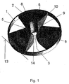
- Each of the three bearing spring segments 2 shown here has a radial inside a channel-shaped spatial surface 5, which extends axially and is designed to be continuously open radially inwards. That definition includes that these internal trough-shaped spatial surfaces 5 the bearing spring segments 2 also on their two each other opposite end faces 6 are configured open.
- This Room surfaces 5 are constant over their entire axial length configured and dimensioned cross-sectional profile. How out 1 and 2, this cross-sectional profile corresponds to FIG trough-shaped surface area 5 an arc.
- this is Cross-sectional profile of the trough-shaped area 5 dimensioned the same and configured to complement the outer surface of the inner Bearing connection element 4 in the area in which this outer Surface of the inner bearing connection element in the area of Passage opening 3 of the bearing spring with the inner surface of the trough-shaped surface area 5 is cooperatively in contact.
- the groove-shaped spatial surfaces 5 are cylindrical curved.
- the cylindrical configuration of the room surfaces 5 is essential for a radial bearing with the features of the invention.
- this cylindrical configuration is a requirement for all types 5 connected inner bearing connection elements, regardless of whether these are circular cylindrical, oval cylindrical or polygonal prismatic, are configured regularly or irregularly.
- the groove which is cylindrically curved in its axial course Room area 5 is designed such that, seen in the axial direction of view, the vertex between the two end faces 6 cylindrical gutter curvature in the central radial central plane 7 ( Figure 3) of the bearing spring.
- the apex of the cylindrical curvature of the spatial surface 5 in the case of FIGS. 1 and 2 shown unstressed configuration of the bearing spring segments in the middle between the two axially opposite end faces 6 this space.
- the intersection between the line of contact 8 and the axial Profile center line 9 of the channel-like spatial surface 5 is in the following as "Central point” of this area 5 denotes.
- the one through this Central point 10 in the central plane 7 of the bearing spring 2 defined radius 5 of the bearing spring segment 2 defines at the point at which it is radial pierces the outer edge of the spring segment 2, the "central Base “11 ( Figure 2) of the spring segment 2.
- the central through this Base 11 perpendicular to the central axis 12 ( Figure 3) of the radial bearing extending tangent 13 ( Figure 2) defines the central axis (13) of the cylindrical curvature of the room surface 5.
- the axially extending groove-shaped can and axially as well as radially inside open space 5 as one cylindrical space are described by a rotation of the Channel cross-section line 8 as a generator by rotation around the Cylinder axis 13 is defined.
- the profile 14 of this not like the regular circular cylinder by a straight line, but by rotating one curved curve generated as the generating cylinder surface is in the Figure 1 clearly recognizable.
- Room surface 5 as an inner surface of a cylindrical over the back describe curved gutter.
- the inner dimension lies in the dimensioning shown in FIG Bearing connection element 4 only loosely flush in the through channel-shaped spatial surfaces 5 of all three bearing spring segments 2 defined, central opening 3 of the without outside Bearing connection element 1 shown radial bearing with the features the invention. Without further countermeasures the cylindrical inner bearing connection element 4 with only a small amount Frictional resistance from the bearing spring of the radial bearing like a plain bearing pull out.
- a radial bearing can be used with the Features of the invention in the radial plane, that is, based on the Automotive engineering, not only as hard as required in the yz plane, but can also be set practically unchanged while pronounced at the same time across this spring-stiff radial plane soft spring profile can be adjusted in the x direction.
- connection can be supplemented by Bonding agent, for example, by vulcanization or Glue on, done. Even when creating a bond between inner bearing connection element and the channel-shaped spatial surface 5 the described storage properties are retained. Limited is only the size of the axial with such connecting means cushionable amplitudes.
- the bearing spring For setting the axial spring characteristics of the radial bearing with the Features of the invention serve the contour of the bearing spring in axial section. The greater the amplitude to be axially cushioned, the longer it must be the axial extent of the room surface 5 can be designed.
- the bearing spring must therefore be designed axially thicker radially on the inside. There however, this leads to a stiffening of the bearing spring in the central area, in order to be able to set soft characteristics in the axial direction axial tiltability of the bearing segments described above by the configuration of tilt lines, that is, an axial weakening of the Bearing spring in the peripheral area of the radial plane.
- the bearing spring profiles to be configured in detail depend on this of the requirements of the intended use of the Radial spring off and are easily configurable by a specialist.
- a radial bearing is shown in the configuration in FIG relatively large amplitudes that can be cushioned in the x-direction in a markedly soft characteristic curve in the X direction is. These characteristics are axially central due to the interaction (i) thick and (ii) axially-peripheral thin design of the bearing spring in Connection with the formation of free-standing bearing spring segments reached. Due to the axial thickness of the profile plate of the bearing spring is a axially considerable length of the trough-shaped spatial surface 5 that 5 in turn allows long rolling paths in the axial direction. This axial profile the bearing spring tapers like a wedge on the inner wall of the outer one Bearing connection element 1 (see also Figure 1).
- this taper can be in a sharp-edged wedge-shaped cutting edge run out, for example, in a V-shaped channel and supportive stabilizing is positively received.
- Such a configuration leads to minimal resistance to tilting of the Spring segments, so also to a minimal resilient Restoring force of the bearing spring in the axial direction.
- Any stiffening of this Limit configuration through an axial reinforcement of the peripheral Spring profile continuously stiffens the axial Spring characteristic of the radial bearing.
- the Opening angle of the conical surface of the segments set so that it extends geometrically on the inner wall of the enclosing Cut the outer bearing connection element 1..
- This geometric Base line of the spring segment is in the system on the inner wall of the outer bearing connection element so far with cylindrical peripheral Widened outer edge that its axial height at least in 'Substantially equal to the axial height of the outer annular Bearing connection element is.
- the spring segment is fixed with in this way connectable to the outer bearing connection element.
- Between this outer foot ring 15 and the conical lateral surfaces of the Radial spring segments are axially opposite one another Throats 16 formed, the axial strength of which is essential Set the spring characteristics of the segmented bearing spring in the x direction allow.
- Optimal opening angles of those formed in the axial section of the bearing spring Triangular surfaces 17 of the spring segments 2 lie for the application 5 in automotive engineering in the range of 50 ° to 150 °, in particular and preferably in the range from 60 ° to 100 °.
- three-part segmentation of the bearing spring of the opening angle of the individual spring segments 2 in the radial plane preferably in Range from 60 ° to 120 °.
- the setting of these in the Radial plane seen opening angle of the spring segments significantly in the overall coordination of the spring characteristics of the radial bearing received.
Landscapes
- Engineering & Computer Science (AREA)
- General Engineering & Computer Science (AREA)
- Mechanical Engineering (AREA)
- Support Of The Bearing (AREA)
- Springs (AREA)
Description
- Figur 1
- ein Radiallager mit den Merkmalen der Erfindung mit drei Federsegmenten in einem äußeren Lageranschlusselement, jedoch ohne inneres Lageranschlusselement;
- Figur 2
- das in Figur 1 dargestellte Ausführungsbeispiel, jedoch ohne äußeres, aber mit innerem Lageranschlusselement; und
- Figur 3
- die in Figur 2 perspektivisch dargestellte Ansicht in einer nahezu in der Radialebene des Radiallagers eingestellten Seitensicht.
Claims (11)
- Radiallager, bestehend aus einem starren Rahmen als äusserem Lageranschlusselement (1) mit einer innenliegend am Rahmen befestigten scheibenförmigen Elastomerfeder, in der senkrecht zur Ebene des Rahmens eine durchgehend und beidseitig offene Ausnehmung (3) zur Aufnahme eines inneren Lageranschlusselementes (4) ausgebildet ist,
gekennzeichnet durch
eine Segmentierung der Feder in Verbindung mit einer sich in dem radialen Innenrand eines jeden Segmentes (2) nach radial innen öffnend konfigurierten und sich axial beidseitig offen rinnenartig erstreckenden zylindrisch gekrümmten Raumfläche (5), die durch eine zur Aussenkonturlinie des inneren Lageranschlusselementes (4) komplementären Generierenden (8) und deren Rotation um eine Zylinderachse (13) definiert ist, die zum einen tangential, also rechtwinklig zur Zentralachse (12) des Radiallagers, ausgerichtet und zum weiteren durch den zentralen Fusspunkt (11) der Anbindung des jeweiligen Federsegments (2) an der Innenwand des Lagerrahmens oder äusseren Lageranschlusselementes (1) verlaufend positioniert ist. - Radiallager nach Anspruch 1,
gekennzeichnet durch
zwei bis zehn im Lagerzentrum unabhängig voneinander axial ausbiegbare Federsegmente (2). - Radiallager nach einem der Ansprüche 1 oder 2,
gekennzeichnet durch
im Lagerrahmen (1) gegeneinander rundum freistehende Federsegmente (2). - Radiallager nach einem der Ansprüche 1 bis 3,
gekennzeichnet durch
eine im Axialschnitt gleichschenklig-dreieckige Kontur der spannungsfreien Federsegmente (2) dergestalt, dass die Spitze dieser Dreieckfläche (17) auf der Fusspunktlinie des Segmentes auf der Innenfläche des Lagerrahmens oder äusseren Lageranschlusselementes (1) liegt und die Basis dieses Dreiecks ein Kreisbogen ist, dessen Krümmungsradius gleich der Schenkellänge der Dreiecksfläche ist. - Radiallager nach einem der Ansprüche 1 bis 4,
gekennzeichnet durch
einen Öffnungswinkel der Axialschnitt-Dreiecksflächen (17) der Federsegmente (2) von radial peripher nach zentral im Bereich von 50° bis 150°. - Radiallager nach einem der Ansprüche 1 bis 4,
gekennzeichnet durch
einen Öffnungswinkel der Axialschnitt-Dreiecksflächen (17) der Federsegmente (2) von radial peripher nach zentral im Bereich von 60° bis 100°. - Radiallager nach einem der Ansprüche 1 bis 6,
gekennzeichnet durch
einen Öffnungswinkel der einzelnen Federscheibensegmente (2) in der Radialebene von zentral nach peripher im Bereich von 60° bis 120°. - Radiallager nach einem der Ansprüche 1 bis 7,
gekennzeichnet durch
eine radial äquidistante Winkelverteilung der Federsegmente (2) im äusseren Lageranschlusselement (1). - Radiallager nach einem der Ansprüche 1 bis 8,
gekennzeichnet durch
ein das innere Lagerelement (4) radial vorspannend aufnehmendes Untermass der Innenabmessungen der zentralaxialen Ausnehmung (3) des Lagers in der radialen Mittelebene der Elastomerfeder (2). - Radiallager nach einem der Ansprüche 1 bis 9,
gekennzeichnet durch
einen keilförmig scharfrandigen oder einen koaxial zur Lagerachse zylindrisch angeschnittenen oder einen mit ebenfalls zylindrischer Aussenfläche wulstringartig konfigurierten Aussenrand (15) der segmentierten scheibenförmigen Elastomerfeder des Lagers in Verbindung mit einer stoffschlüssigen oder formschlüssigen und im Ergebnis axial gelenkigen Anbindung (16) der Elastomerfeder (2) an der Innenwand des äusseren Lageranschlusselementes (1). - Verwendung des Radiallagers mit den Merkmalen nach einem der Ansprüche 1 bis 10 als Aufhängung für Abgasleitungen und deren Bestandteile im Kraftfahrzeugbau.
Applications Claiming Priority (2)
| Application Number | Priority Date | Filing Date | Title |
|---|---|---|---|
| DE10137508 | 2001-07-26 | ||
| DE10137508A DE10137508A1 (de) | 2001-07-26 | 2001-07-26 | Radiallager |
Publications (3)
| Publication Number | Publication Date |
|---|---|
| EP1279856A2 EP1279856A2 (de) | 2003-01-29 |
| EP1279856A3 EP1279856A3 (de) | 2003-05-14 |
| EP1279856B1 true EP1279856B1 (de) | 2004-10-13 |
Family
ID=7693874
Family Applications (1)
| Application Number | Title | Priority Date | Filing Date |
|---|---|---|---|
| EP02014363A Expired - Lifetime EP1279856B1 (de) | 2001-07-26 | 2002-06-27 | Radiallager |
Country Status (2)
| Country | Link |
|---|---|
| EP (1) | EP1279856B1 (de) |
| DE (2) | DE10137508A1 (de) |
Families Citing this family (1)
| Publication number | Priority date | Publication date | Assignee | Title |
|---|---|---|---|---|
| DE102012022536B4 (de) | 2012-11-16 | 2018-06-21 | Anvis Deutschland Gmbh | Elastisches Radiallager für eine schwingfähige Anbindung eines Fahrzeugsfunktionsteils |
Family Cites Families (4)
| Publication number | Priority date | Publication date | Assignee | Title |
|---|---|---|---|---|
| GB1248977A (en) * | 1967-11-09 | 1971-10-06 | Stavebni Strojirenstvi A Lehka | Shock absorber |
| JPS55142143A (en) * | 1979-04-20 | 1980-11-06 | Japanese National Railways<Jnr> | Anti-vibration grip |
| DE19805401C2 (de) * | 1998-02-11 | 2003-06-12 | Draebing Kg Wegu | Elastomerfeder mit einer Buchse zur Aufnahme eines Lagerbolzens |
| IT245842Y1 (it) * | 1998-05-20 | 2002-03-26 | Gate Spa | Tassello smorzatore di vibrazioni. |
-
2001
- 2001-07-26 DE DE10137508A patent/DE10137508A1/de not_active Withdrawn
-
2002
- 2002-06-27 DE DE2002501269 patent/DE50201269D1/de not_active Expired - Fee Related
- 2002-06-27 EP EP02014363A patent/EP1279856B1/de not_active Expired - Lifetime
Also Published As
| Publication number | Publication date |
|---|---|
| DE10137508A1 (de) | 2003-02-13 |
| EP1279856A3 (de) | 2003-05-14 |
| DE50201269D1 (de) | 2004-11-18 |
| EP1279856A2 (de) | 2003-01-29 |
Similar Documents
| Publication | Publication Date | Title |
|---|---|---|
| DE4340494A1 (de) | Federträger mit verstellbaren Federteller | |
| DE102009027319A1 (de) | Elastische Buchse | |
| DE4111318A1 (de) | Hydraulische, buchsenfoermige daempfungsvorrichtung | |
| EP0269890A1 (de) | Tragfedersystem | |
| EP3749883B1 (de) | Feder für ein rückschlagventil, rückschlagventil mit einer derartigen feder, regelbarer schwingungsdämpfer mit einem solchen rückschlagventil sowie kraftfahrzeug mit einem derartigen regelbaren schwingungsdämpfer | |
| DE102009041807B4 (de) | Gelenk mit an einem Zapfen befestigten Kugelkopf sowie Gleitlagerfolie für ein solches Gelenk | |
| EP1071892A1 (de) | Seilrolle | |
| EP3284975A1 (de) | Planetenachse | |
| DE3106690A1 (de) | Gummifeder fuer die elastische lagerung von maschinen | |
| EP0327864A1 (de) | Federelement | |
| EP2134555A1 (de) | Befestigungselement, insbesondere zur verbindung zweier teile in einem fahrwerk | |
| DE102009032919B4 (de) | Federungsanordnung mit einer Blattfeder aus einem Faserverbundwerkstoff | |
| DE3111015A1 (de) | Schwingungs- und stosskraefte absorbierendes befestigungselement zur abstuetzung einer last | |
| DE4438756A1 (de) | Federträger mit verstellbarem Federteller | |
| DE4016223C2 (de) | Ringstützlager | |
| DE10041954C1 (de) | Kolbenring, insbesondere für einen Kolben eines Schwingungsdämpfers | |
| DE10137508A1 (de) | Radiallager | |
| DE102018116557A1 (de) | Schwingungsdämpfer, Kolben und Verfahren zur Einstellung der Dämpfung | |
| DE102006052917B4 (de) | Hydrolager mit Wegbegrenzung | |
| DE3907067C2 (de) | ||
| DE69518068T2 (de) | Fahrzeugaufhängungssystem | |
| EP0670233A2 (de) | Aufhängung bewegter Bauteile bei Kraftfahrzeugen | |
| DE102008036647A1 (de) | Taumelgelenkbeschlag für einen Kraftfahrzeugsitz | |
| EP0763670A2 (de) | Reibungsdämpfer zur Bewegungsdämpfung in mechanischen Systemen | |
| EP2187088B1 (de) | Schwingungstilger |
Legal Events
| Date | Code | Title | Description |
|---|---|---|---|
| PUAI | Public reference made under article 153(3) epc to a published international application that has entered the european phase |
Free format text: ORIGINAL CODE: 0009012 |
|
| AK | Designated contracting states |
Designated state(s): AT BE CH CY DE DK ES FI FR GB GR IE IT LI LU MC NL PT SE TR |
|
| AX | Request for extension of the european patent |
Extension state: AL LT LV MK RO SI |
|
| PUAL | Search report despatched |
Free format text: ORIGINAL CODE: 0009013 |
|
| RIC1 | Information provided on ipc code assigned before grant |
Ipc: 7F 01N 7/18 B Ipc: 7F 16F 1/387 A |
|
| AK | Designated contracting states |
Designated state(s): AT BE CH CY DE DK ES FI FR GB GR IE IT LI LU MC NL PT SE TR |
|
| AX | Request for extension of the european patent |
Extension state: AL LT LV MK RO SI |
|
| 17P | Request for examination filed |
Effective date: 20031104 |
|
| GRAP | Despatch of communication of intention to grant a patent |
Free format text: ORIGINAL CODE: EPIDOSNIGR1 |
|
| AKX | Designation fees paid |
Designated state(s): DE FR |
|
| GRAS | Grant fee paid |
Free format text: ORIGINAL CODE: EPIDOSNIGR3 |
|
| GRAA | (expected) grant |
Free format text: ORIGINAL CODE: 0009210 |
|
| AK | Designated contracting states |
Kind code of ref document: B1 Designated state(s): DE FR |
|
| REG | Reference to a national code |
Ref country code: IE Ref legal event code: FG4D Free format text: GERMAN |
|
| REF | Corresponds to: |
Ref document number: 50201269 Country of ref document: DE Date of ref document: 20041118 Kind code of ref document: P |
|
| REG | Reference to a national code |
Ref country code: IE Ref legal event code: FD4D |
|
| PLBE | No opposition filed within time limit |
Free format text: ORIGINAL CODE: 0009261 |
|
| STAA | Information on the status of an ep patent application or granted ep patent |
Free format text: STATUS: NO OPPOSITION FILED WITHIN TIME LIMIT |
|
| ET | Fr: translation filed | ||
| 26N | No opposition filed |
Effective date: 20050714 |
|
| PG25 | Lapsed in a contracting state [announced via postgrant information from national office to epo] |
Ref country code: DE Free format text: LAPSE BECAUSE OF NON-PAYMENT OF DUE FEES Effective date: 20060103 |
|
| PGFP | Annual fee paid to national office [announced via postgrant information from national office to epo] |
Ref country code: FR Payment date: 20140619 Year of fee payment: 13 |
|
| REG | Reference to a national code |
Ref country code: FR Ref legal event code: ST Effective date: 20160229 |
|
| PG25 | Lapsed in a contracting state [announced via postgrant information from national office to epo] |
Ref country code: FR Free format text: LAPSE BECAUSE OF NON-PAYMENT OF DUE FEES Effective date: 20150630 |