EP1279832B1 - Förderung von Fluiden durch einen Mikrokanal in einem elastischen Substrat durch regelmässiges Zusammendrücken von Teilen des Mikrokanals - Google Patents
Förderung von Fluiden durch einen Mikrokanal in einem elastischen Substrat durch regelmässiges Zusammendrücken von Teilen des Mikrokanals Download PDFInfo
- Publication number
- EP1279832B1 EP1279832B1 EP02014386A EP02014386A EP1279832B1 EP 1279832 B1 EP1279832 B1 EP 1279832B1 EP 02014386 A EP02014386 A EP 02014386A EP 02014386 A EP02014386 A EP 02014386A EP 1279832 B1 EP1279832 B1 EP 1279832B1
- Authority
- EP
- European Patent Office
- Prior art keywords
- microchannel
- fluid
- substrate
- rotor
- chemical
- Prior art date
- Legal status (The legal status is an assumption and is not a legal conclusion. Google has not performed a legal analysis and makes no representation as to the accuracy of the status listed.)
- Expired - Lifetime
Links
- 239000012530 fluid Substances 0.000 title claims description 124
- 239000000758 substrate Substances 0.000 title claims description 85
- 238000012546 transfer Methods 0.000 title claims description 10
- 238000000034 method Methods 0.000 claims description 64
- 238000006243 chemical reaction Methods 0.000 claims description 21
- 239000000126 substance Substances 0.000 claims description 20
- 230000008569 process Effects 0.000 claims description 15
- 150000001875 compounds Chemical class 0.000 claims description 9
- 238000002032 lab-on-a-chip Methods 0.000 claims description 9
- 238000012545 processing Methods 0.000 claims description 9
- 238000000926 separation method Methods 0.000 claims description 6
- 238000004458 analytical method Methods 0.000 claims description 5
- 230000015572 biosynthetic process Effects 0.000 claims description 5
- 239000000203 mixture Substances 0.000 claims description 5
- 238000001311 chemical methods and process Methods 0.000 claims description 4
- 238000003786 synthesis reaction Methods 0.000 claims description 4
- 238000000605 extraction Methods 0.000 claims description 3
- 238000000746 purification Methods 0.000 claims description 3
- 238000002156 mixing Methods 0.000 claims 2
- 238000004448 titration Methods 0.000 claims 2
- 238000012384 transportation and delivery Methods 0.000 description 32
- 238000002474 experimental method Methods 0.000 description 18
- 229920000435 poly(dimethylsiloxane) Polymers 0.000 description 12
- 239000004205 dimethyl polysiloxane Substances 0.000 description 11
- 235000013870 dimethyl polysiloxane Nutrition 0.000 description 11
- CXQXSVUQTKDNFP-UHFFFAOYSA-N octamethyltrisiloxane Chemical compound C[Si](C)(C)O[Si](C)(C)O[Si](C)(C)C CXQXSVUQTKDNFP-UHFFFAOYSA-N 0.000 description 11
- 238000004987 plasma desorption mass spectroscopy Methods 0.000 description 11
- 238000005516 engineering process Methods 0.000 description 10
- 239000003153 chemical reaction reagent Substances 0.000 description 8
- 238000004519 manufacturing process Methods 0.000 description 8
- 238000011160 research Methods 0.000 description 8
- 239000000463 material Substances 0.000 description 6
- 239000012528 membrane Substances 0.000 description 6
- 238000012544 monitoring process Methods 0.000 description 6
- 230000001965 increasing effect Effects 0.000 description 5
- 230000000704 physical effect Effects 0.000 description 5
- 230000001276 controlling effect Effects 0.000 description 4
- 238000004049 embossing Methods 0.000 description 4
- 229920001296 polysiloxane Polymers 0.000 description 4
- 238000003825 pressing Methods 0.000 description 4
- 230000010349 pulsation Effects 0.000 description 4
- 229920001730 Moisture cure polyurethane Polymers 0.000 description 3
- 229940079593 drug Drugs 0.000 description 3
- 239000003814 drug Substances 0.000 description 3
- 230000005684 electric field Effects 0.000 description 3
- 239000012467 final product Substances 0.000 description 3
- 239000000047 product Substances 0.000 description 3
- 239000004065 semiconductor Substances 0.000 description 3
- 230000008901 benefit Effects 0.000 description 2
- 238000004587 chromatography analysis Methods 0.000 description 2
- 238000007796 conventional method Methods 0.000 description 2
- 238000013461 design Methods 0.000 description 2
- 238000010586 diagram Methods 0.000 description 2
- 229920001971 elastomer Polymers 0.000 description 2
- 238000005370 electroosmosis Methods 0.000 description 2
- 238000005459 micromachining Methods 0.000 description 2
- 230000002572 peristaltic effect Effects 0.000 description 2
- 238000000206 photolithography Methods 0.000 description 2
- 239000004033 plastic Substances 0.000 description 2
- 229920003023 plastic Polymers 0.000 description 2
- 239000002861 polymer material Substances 0.000 description 2
- 230000002194 synthesizing effect Effects 0.000 description 2
- 108020004414 DNA Proteins 0.000 description 1
- 102000004190 Enzymes Human genes 0.000 description 1
- 108090000790 Enzymes Proteins 0.000 description 1
- 241001465754 Metazoa Species 0.000 description 1
- 239000011149 active material Substances 0.000 description 1
- 238000013459 approach Methods 0.000 description 1
- 238000012742 biochemical analysis Methods 0.000 description 1
- 239000006227 byproduct Substances 0.000 description 1
- 238000005251 capillar electrophoresis Methods 0.000 description 1
- 230000008859 change Effects 0.000 description 1
- 230000003247 decreasing effect Effects 0.000 description 1
- 238000001514 detection method Methods 0.000 description 1
- 238000011161 development Methods 0.000 description 1
- 238000007599 discharging Methods 0.000 description 1
- 239000013013 elastic material Substances 0.000 description 1
- 230000005611 electricity Effects 0.000 description 1
- 238000003487 electrochemical reaction Methods 0.000 description 1
- 230000007613 environmental effect Effects 0.000 description 1
- 239000003344 environmental pollutant Substances 0.000 description 1
- 239000003256 environmental substance Substances 0.000 description 1
- 238000011049 filling Methods 0.000 description 1
- 239000012847 fine chemical Substances 0.000 description 1
- 239000007789 gas Substances 0.000 description 1
- 239000011521 glass Substances 0.000 description 1
- 230000036541 health Effects 0.000 description 1
- 238000004128 high performance liquid chromatography Methods 0.000 description 1
- 230000001939 inductive effect Effects 0.000 description 1
- 239000007788 liquid Substances 0.000 description 1
- 239000000314 lubricant Substances 0.000 description 1
- 238000007726 management method Methods 0.000 description 1
- 238000012986 modification Methods 0.000 description 1
- 230000004048 modification Effects 0.000 description 1
- 238000001080 multi-layer soft lithography Methods 0.000 description 1
- 239000002858 neurotransmitter agent Substances 0.000 description 1
- 230000000737 periodic effect Effects 0.000 description 1
- 239000003504 photosensitizing agent Substances 0.000 description 1
- -1 poly(dimethylsiloxane) Polymers 0.000 description 1
- 229920000642 polymer Polymers 0.000 description 1
- 238000007781 pre-processing Methods 0.000 description 1
- 238000004801 process automation Methods 0.000 description 1
- 230000002035 prolonged effect Effects 0.000 description 1
- 102000004169 proteins and genes Human genes 0.000 description 1
- 108090000623 proteins and genes Proteins 0.000 description 1
- 238000010223 real-time analysis Methods 0.000 description 1
- 230000001105 regulatory effect Effects 0.000 description 1
- 238000012827 research and development Methods 0.000 description 1
- 239000007779 soft material Substances 0.000 description 1
- 238000004528 spin coating Methods 0.000 description 1
- 239000007858 starting material Substances 0.000 description 1
- 238000003860 storage Methods 0.000 description 1
- 238000009966 trimming Methods 0.000 description 1
- 239000011800 void material Substances 0.000 description 1
- 239000002699 waste material Substances 0.000 description 1
- XLYOFNOQVPJJNP-UHFFFAOYSA-N water Substances O XLYOFNOQVPJJNP-UHFFFAOYSA-N 0.000 description 1
Images



Classifications
-
- G—PHYSICS
- G01—MEASURING; TESTING
- G01N—INVESTIGATING OR ANALYSING MATERIALS BY DETERMINING THEIR CHEMICAL OR PHYSICAL PROPERTIES
- G01N1/00—Sampling; Preparing specimens for investigation
-
- G—PHYSICS
- G01—MEASURING; TESTING
- G01N—INVESTIGATING OR ANALYSING MATERIALS BY DETERMINING THEIR CHEMICAL OR PHYSICAL PROPERTIES
- G01N30/00—Investigating or analysing materials by separation into components using adsorption, absorption or similar phenomena or using ion-exchange, e.g. chromatography or field flow fractionation
- G01N30/02—Column chromatography
- G01N30/26—Conditioning of the fluid carrier; Flow patterns
- G01N30/28—Control of physical parameters of the fluid carrier
- G01N30/32—Control of physical parameters of the fluid carrier of pressure or speed
-
- F—MECHANICAL ENGINEERING; LIGHTING; HEATING; WEAPONS; BLASTING
- F04—POSITIVE - DISPLACEMENT MACHINES FOR LIQUIDS; PUMPS FOR LIQUIDS OR ELASTIC FLUIDS
- F04B—POSITIVE-DISPLACEMENT MACHINES FOR LIQUIDS; PUMPS
- F04B43/00—Machines, pumps, or pumping installations having flexible working members
- F04B43/02—Machines, pumps, or pumping installations having flexible working members having plate-like flexible members, e.g. diaphragms
- F04B43/04—Pumps having electric drive
- F04B43/043—Micropumps
-
- F—MECHANICAL ENGINEERING; LIGHTING; HEATING; WEAPONS; BLASTING
- F04—POSITIVE - DISPLACEMENT MACHINES FOR LIQUIDS; PUMPS FOR LIQUIDS OR ELASTIC FLUIDS
- F04B—POSITIVE-DISPLACEMENT MACHINES FOR LIQUIDS; PUMPS
- F04B43/00—Machines, pumps, or pumping installations having flexible working members
- F04B43/12—Machines, pumps, or pumping installations having flexible working members having peristaltic action
-
- G—PHYSICS
- G01—MEASURING; TESTING
- G01N—INVESTIGATING OR ANALYSING MATERIALS BY DETERMINING THEIR CHEMICAL OR PHYSICAL PROPERTIES
- G01N30/00—Investigating or analysing materials by separation into components using adsorption, absorption or similar phenomena or using ion-exchange, e.g. chromatography or field flow fractionation
- G01N30/02—Column chromatography
- G01N30/26—Conditioning of the fluid carrier; Flow patterns
- G01N30/28—Control of physical parameters of the fluid carrier
- G01N30/32—Control of physical parameters of the fluid carrier of pressure or speed
- G01N2030/326—Control of physical parameters of the fluid carrier of pressure or speed pumps
-
- Y—GENERAL TAGGING OF NEW TECHNOLOGICAL DEVELOPMENTS; GENERAL TAGGING OF CROSS-SECTIONAL TECHNOLOGIES SPANNING OVER SEVERAL SECTIONS OF THE IPC; TECHNICAL SUBJECTS COVERED BY FORMER USPC CROSS-REFERENCE ART COLLECTIONS [XRACs] AND DIGESTS
- Y10—TECHNICAL SUBJECTS COVERED BY FORMER USPC
- Y10T—TECHNICAL SUBJECTS COVERED BY FORMER US CLASSIFICATION
- Y10T436/00—Chemistry: analytical and immunological testing
- Y10T436/25—Chemistry: analytical and immunological testing including sample preparation
- Y10T436/2575—Volumetric liquid transfer
Definitions
- the present invention relates to a method and device for accurately handling and delivering infinitesimal amounts of fluid in an elastic polymeric substrate of microfluidic devices used in chemical and biochemical analyses, synthesis and detection.
- the method and device deliver fluid in microchannels formed within an elastic polymeric substrate by using a rotor to apply external force onto the elastic polymeric substrate so that the fluid in the microchannels is forced therethrough.
- the document EP 1 065 378 A discloses a method and system for causing a fluid to travel within an elastic microchannel and for handling the fluid.
- an elastomeric block having microchannels formed therein is used for controlling a fluid flow of the fluid transferred through the microchannels.
- a microfabricated system having an improved function of regulating a fluid flow is taken into account.
- a membrane portion is provided in order to separate a plurality of microchannels formed in the elastomeric structure.
- the membrane portion comprises an elastomeric membrane deflectable into one of the microchannels when the membrane is actuated. Hence, by applying an actuation force to the membrane portion, the membrane portion is deflected into one of the microchannels, thereby controlling the fluid flow through the elastomeric structure.
- Lab-on-a-chip is a chemical microprocessor made by integrating many kinds of apparatuses on a substrate (chip) having a dimension of several centimeters being made of glass, silicone or plastic using photolithography or micromachining used generally in semiconductor technology, and allows automated experiments to be conducted with high speed, high efficiency and low cost (Kovas, Anal. Chem. 68 (1996) 407A-412A). By miniaturizing and integrating many apparatuses onto a chip needed for experimentation and by automating the respective experiment processes to be conducted consecutively, experiments can be conducted more efficiently.
- the most common method employs electric fields.
- the method of using electric fields can control the flow of solution by using capillary electric osmosis generated when a voltage is applied at both ends of the microchannel filled with the solution without using an additional pump or valve. It is also possible to analyze samples on the chip because separation of the sample using capillary electrophoresis is possible (Harrison, Science 261 (1993) pp.895-897; Jacobson, Anal. Chem. 66 (1994) pp.4127-4132; Li, Anal. Chem. 69 (1997) pp. 1564-1568; Kopp, Science 280 (1998) pp.1046-1048).
- the apparatus for this method is simple and accordingly, this method is used most commonly in the field of delivering solutions in microchannels such as those in a lab-on-a-chip.
- this method is used most commonly in the field of delivering solutions in microchannels such as those in a lab-on-a-chip.
- controlling the delivery of the solution is difficult.
- Accurate delivery is also difficult or impossible if various kinds of solutions are delivered because the flow rate of the solution is affected by the physical properties, such as acidity (pH), ionic strength and viscosity, of the solution to be delivered and microchannel surface condition.
- waste of unnecessary reagents or samples is increased since the fluid must be filled from the pump to the microchannels to connect the external micropump with the microchannels of the lab-on-a-chip. Also, the fluid can leak from the portion connecting the chip and the external micropump since the pressure for delivering the solution is undesirably generated at the external portions of the chip and accordingly, complicated and sophisticated design and assembly are necessary.
- the object underlying the present invention is to provide a control system which is suitable and adapted to take account of efficiently handling and delivering fluids in an infinitesimal amount (in the range of picoliters) up to a small amount (in the range of milliliters) regardless of the kind of fluid, but to provide a system having a simple structure.
- the present invention provides a method and device for handling and delivering fluid in an elastic polymeric substrate, and for delivering various kinds of fluids in an infinitesimal amount in the range from picoliters to milliliters at a constant rate regardless of the physical properties of the fluid in the substrate having a microchannel therein. Additional external devices or structures on the substrate are not required to handle and deliver the fluid.
- a gist of the present invention involves the identification of conventional art problems related to handling and delivering accurate and infinitesimal amounts of fluid through microchannels.
- the present invention solves such problems by periodically applying an external (mechanical) force onto a polymeric substrate using a rotor to compress the microchannel having fluid therein, and periodically releasing the applied external force from the substrate to decompress the microchannel like peristaltic pump to deliver fluid therethrough.
- a fluid is transferred through the microchannel by periodically squeezing selective portions thereof, and a chemical operation is performed by using the transferred fluid.
- substrate has an identical meaning with the term “chip” and are used interchangeably to describe structural aspects of the present invention.
- FIG. 1A The principle of how fluid is delivered in the present invention is shown in Figures 1A to 1C.
- the fluid F is delivered by applying an external (mechanical) force on a portion of the substrate above a microchannel 22 using a rotor 10 with a toothed wheel shape.
- the rotor 10 is rotated to sequentially add pressure on the microchannel 22 formed within the substrate 20.
- the fluid F in the microchannel 22 is first compressed by an inner wall of the microchannel 22.
- a second gear tooth 102 of the rotor 10 also begins to apply pressure along a subsequent portion of the microchannel 22 with the first gear tooth 101 still compressing the first portion of the microchannel 22 as shown in Figure 2B. Thereafter, the first gear tooth 101 moves away from the elastic polymeric substrate surface while the second gear tooth 102 continues to apply pressure on the microchannel 22, as shown in Figure 1C. Thereafter, the subsequent gear teeth continue to apply periodic pressure on the microchannel 22 through the substrate 20 so that the fluid F therein is delivered therethrough.
- the rotational shaft of the rotor 10 can be positioned parallel to the surface of the substrate 20 and across the microchannel 22 above the substrate 20.
- the rotational shaft can also be moved vertically towards or away from the substrate 20 to adjust the amount of external pressure applied from the rotor 10.
- the shaft of the rotor 10 preferably does not move in the longitudinal direction along the microchannel 22, as the fluid F in the microchannel 22 is delivered along the rotational direction of the rotor 10 as the gear teeth apply pressure to the substrate 20.
- the external force applied by the rotor 10 onto the microchannel 22 is only limited by the diameter size of the rotor 10 because the rotor 10 itself does not move in the longitudinal direction along the microchannel 22 and thus, the fluid F can be continuously transferred in one direction as long as fluid is continuously provided into the microchannel 22. In other words, the rotor 10 itself needs not to be displaced to move the microchannel 22.
- the rotation of a rotor 10 held at a fixed position above the substrate 20 allows fluid transfer by periodically squeezing selective portions of the microchannel 22.
- the amount and delivery rate of the fluid are generally determined by the internal size of the microchannel 22 and the rotation speed of the rotor 10, which presses the microchannel 22.
- a characteristic of the present invention is that a means for delivering fluid is not included in the substrate itself. Therefore, it is easy to design and manufacture the substrate for fluid handling because no complicated manufacturing processes for embodying structures or devices in the substrate to deliver the fluid are necessary. By such characteristics, the present invention can be directly applied to various types of substrate or chip structures having microchannels formed therein.
- FIG. 2 An example of an apparatus for accurately delivering fluid F in the substrate 20 is shown in Figure 2.
- a rotor 10 shaped in the form of a "toothed wheel” is used to press the microchannel 22 by applying an external force on the microchannel 22 in the substrate 20, as the rotor 10 rotates by means of a stepping motor 40.
- the rotor 10 connected with the stepping motor 40 can be installed in a manual z-axis translational device 50 and accordingly, the rotor 10 can press the microchannel 22 by applying an external force onto the substrate 20 by manually operating the z-axis of the z-axis translational device 50 to lower or raise the rotor 10 position above the substrate 20.
- the means for applying external force on the substrate 20 can be manual z-axis translational devices as in this Example.
- the rotor 10 positioning can also be automated by using an additional motor, pump, electromagnet or the like.
- a DC motor or servomotor as well as a stepping motor can be used.
- a device for storing the fluid can be included in the substrate 20 or in case the amount of fluid exceeds the limitation of the internal capacity of the substrate 20, an external storage container 30 can be additionally connected with the microchannel 22 through a connection pipe or the like.
- an outlet container 31 can be attached to the other end of the microchannel 22 for receiving the delivered fluid.
- Figure 3 is an example of the method for manufacturing a microchannel chip made of PDMS, which is a kind of elastic polymer.
- any type of material can be used on condition that it allows blockage of the microchannel when pressed.
- polymeric materials such as rubber, silicone type rubber or plastics having certain elasticity are used.
- methods of making a microchannel in the substrate in addition to a method of hardening after pouring a pre-polymer material like PDMS to a mold as described above, methods of directly pressing a flat substrate surface with a embossed mold, applying hot embossing to the substrate, using mechanical means to process the substrate.and forming microchannels with light or heat using laser energy or other methods of applying light or heat energy can be used.
- Various types of fluids including liquids and gases can be delivered through the microchannels in accordance with the present invention.
- the air in the microchannels By filling the fluid inlet connected to the microchannel with the desired fluid and by operating the rotor to apply pressure on the substrate portions above the microchannel, the air in the microchannels first is discharged and the void created in the microchannel is filled by the fluid from the inlet to thereby allow continuous and accurate fluid transfer through the microchannel. Accordingly, it is not necessary to pre-fill the microchannel with the desired fluid to be delivered.
- the volume of the delivered fluid in the apparatus is determined by the size (e.g., the diameter or cross-section) of the microchannel in the substrate surface area pressed by the rotor, the rotation speed of the rotor and the structure of the rotor.
- the rotation speed of the rotor is determined by the rotation speed of the stepping motor or other driving means connected with the rotor. Namely, the rotation speed of the rotor is determined by an angular resolution of the stepping motor and a frequency of a pulse signal input to the stepping motor.
- the stepping motor used in the present invention can have an angular resolution of 1° per pulse, and the pulse signal can allow the rotation speed of the rotor to be controlled by inputting signals of various frequencies between several Hz and hundreds of Hz to generate a desired rotational speed of the rotor.
- the device according to the present invention capable of continuously supplying fluid through microchannels has an advantage in that it can be applied as a simple device in various fields requiring chemical compounds and mixtures to be supplied and/or handled continuously.
- the amount of fluid supply can be easily controlled according to described conditions, in addition to supplying fluid at a constant rate for a prolonged period of time.
- the present invention can be applied to numerous devices including devices for supplying medical or other types of fluids to humans, animals or plants, for supplying compounds or mixtures in chemical or biological processing, and for supplying a culture solution in a cell or microbe cultivator, just to name a few.
- Fluids can be accurately and efficiently handled/delivered through microchannels using the apparatus of Figure 2 and the single microchannel substrate.
- Figure 4 illustrates the method for delivering fluid in a single microchannel substrate made of elastic material.
- the delivery rate of the fluid can be measured with a velocity sensor but in the present example, the delivery rate was calculated by measuring the fluid moving time upon observing the moving distance of the boundary between the fluid F and the air in the microchannel 22 using a monitor connected with a Charged-Coupled Device (CCD) camera.
- CCD Charged-Coupled Device
- the single microchannel substrate as described in Figure 5 can be placed on the apparatus as described in Figure 2.
- the single microchannel substrate in Figure 5 has a microchannel having a width of about 50 ⁇ m, depth of about 30 ⁇ m and length of about 4cm and has graduations formed on the side portion of the microchannel 22 to observe fluid F flow within the microchannel 22.
- the manual z-axis translational device 5 can be operated to control the rotor 10 for pressing the microchannel substrate.
- the fluid F is delivered through the microchannel 22 by rotating the rotor 10 connected to the stepping motor.
- the process is preferably performed while the user observes the process by a CCD camera.
- the stepping motor is stopped, and the input signal frequency of the stepping motor is set to correspond with the desired rotation speed.
- Figure 6 is a graph showing the delivering speed of the fluid F according to the rotation speeds of the rotor 10. As shown in Figure 6, the delivery rate is from about 50 picoliters/sec to about 2.5 nanoliters/sec. If the performance of the motor which rotates the rotor 10 is improved and the friction between the rotor 10 and the substrate 20 is reduced by for example, applying lubricant on the substrate 20, the rotation speed of the rotor 10 can be increased and therefore the fluid delivery rate can be increased even further.
- the delivery rate of the fluid F can also be adjusted by varying the width and the depth of the microchannel 22.
- the delivery rate is decreased to 1/50 from the example in Figure 6 and accordingly, by the same method as in Figure 4, the fluid delivery rate of about 1 picoliters/sec to about 50 picoliters/sec can be obtained.
- the delivery rate of the fluid can be adjusted from about 0.1 ⁇ L/sec to about 5 ⁇ L /sec.
- the range of delivery rate can be controlled by adjusting the width and the depth of the microchannel 22 according to the desired usage.
- the delivery rate of the fluid F can be controlled by adjusting the rotation speed of the rotor 10 within the range of delivery rate.
- Example 3 the experiment is carried out in the same manner as in Example 2, and the single microchannel substrate has a microchannel with a width and depth of about 50 ⁇ m and 30 ⁇ m, respectively.
- a pulse signal having a frequency of about 100Hz or 160Hz was inputted to the stepping motor for rotating the rotor.
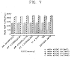
- Figure 7 is a diagram showing the results of the delivery of various kinds of fluids and shows that the delivery rates of various kinds of fluids having different acidity, viscosity and ionic strength according to two speeds of rotor are the same regardless of the type of fluid.
- the flow stream of the fluid according to the present invention may have a pulsatory characteristic instead of a continuously smooth characteristic. As shown in Figure 1, this is because the fluid flow is intermittently blocked in the microchannel 22 being periodically pressed regularly by the gear-like teeth of the rotor 10 during fluid delivery. Such pulsation is a disadvantage commonly occurring in conventional micropumps and does not cause a major problem in experiments requiring simple delivery of solution in a certain amount. However, pulsation is a serious problem in applications requiring a continuous stream of fluid being supplied at a constant rate.
- Figure 8 shows an apparatus for reducing the pulsatory characteristics in the flow stream of the delivered fluid in accordance with the present invention.
- the fluid is combined at portion A of the substrate 20 connected with a single microchannel 22.
- the two rotors 10a and 10b are positioned so that the teeth of one rotor are staggered with those of the other rotor as shown in Figure 9B.
- each microchannel 22a and 22b provides a pulsatory stream.
- the present invention can even be applied to chemical experiments and applications that require a continuous and constant flow of fluid.
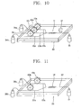
- Figure 10 shows an apparatus for real-time monitoring of changes in the concentrations of certain components contained in samples.
- the method can be used in applications requiring real-time monitoring, such as monitoring of the discharging water of a plant, quality management of products made from the fluid or other fluid handling applications.
- Real-time analysis is performed by introducing the sample to be analyzed into the substrate 20 through the sample inlet part 25 of the apparatus in Figure 10, after processing to detect the introduced sample by inducing a chemical reaction in the reaction portion 11 using a chemical reagent stored in portions 34a and 34b.
- a reaction of a sample and a chemical reagent can take place in one portion of the microchannel 20, i.e., reaction portion 11, as shown in Figure 10. It is also possible to change the structure of the microchanel 20 so that the sample can react with different chemical reagents in order or in parallel. Also, if a valve-like element is formed in the microchannel, the supply of samples or reagents can be further controlled through the microchannel to deliver continuous or non-continuous amounts.
- the microchannel 22 can be used in performing analyses like those performed during chromatography.
- analyzers for chemical compounds can be made.
- Such analyzers can be used in instruments for developing new medicines, for biochemical analysis, for pre-processing of chemical samples, for analyzing molecules, for analyzing environmental pollutes, for detecting or discriminating of chemical or biochemical weapons, for monitoring of chemical or biological processing, and for medical diagnosing and health examining, just to name a few.
- FIG. 11 is a view showing an apparatus, which can continuously perform a desired reaction or reactions in accordance with the present invention.
- the present invention can continuously introduce chemical reagents into the substrate 20 through the inlet units 36a and 36b, carry out the reaction in the reaction portion 14 and gather the product at the outlet unit 37.
- the processes of extraction, separation and/or purification can be performed to remove by-products from the desired final product of the reaction.
- the method can be efficiently applied in case a desired amount of substance must be obtained or identical reactions must be repeated continuously.
- the synthetic process conventionally performed by manual labor can be replaced by using the method and device of the present invention with a reaction substrate to achieve a so-called "automated small-scale chemical plant".
- the present invention can be applied to various chemical processes by appropriately modifying the structure of the microchannels in the substrate.
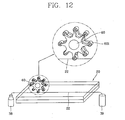
- FIG. 12 is a view showing a rotor 60 designed to apply pressure to the substrate 20 above the microchannel 22 using a plurality of miniature rollers 601 operatively connected at the end portion of each tooth of the rotor 60. Accordingly, the friction between the teeth of the rotor 60 and the contact surface on substrate 20 can be minimized, and the rotor 60 can rotate quickly without.damaging the substrate 20, thereby to obtain a rapid fluid delivery rate.
- a method and apparatus for efficiently handling and delivering fluids in an infinitesimal amount (in the range of picoliters) up to a small amount (in the range of milliliters) regardless of the kind of fluid can be achieved with a simple structure.
- the method and apparatus for handling and delivering fluid in the elastic substrate according to the present invention can be applied as an efficient means for handling and delivering fluids in various fields of technology requiring the use of infinitesimal amounts of fluid.
- the present invention can be applied in developing new substances by synthesizing many kinds of substances simultaneously through combinatorial chemistry technologies, searching for new medicines by identifying the characteristics of many kinds of substances, life science technology dealing with infinitesimal amounts of physiologically active materials such as enzymes, proteins, DNA, neurotransmitters and the like, developing portable analyzing instruments for detecting and discriminating environmental pollutants or chemical, biological and radiological weapons, and developing household clinical diagnosing instruments.
- the present invention can be applied when a number of chemical processes, such as synthesis of a substance or analysis of samples, need to be carried out in a substrate, such as the so-called lab-on-a-chip technology which is expected to be rapidly developed in the future.
- a substrate such as the so-called lab-on-a-chip technology which is expected to be rapidly developed in the future.
- Such technology requires that infinitesimal amounts of fluid be provided efficiently without having to employ a complicated apparatus or structure in the substrate.
- Designing and manufacturing of the substrate is very simple and consequently, the present invention can contribute to the research and practical use of lab-on-a-chip technology, as well as in many other field of research and development.
Landscapes
- Engineering & Computer Science (AREA)
- General Engineering & Computer Science (AREA)
- Mechanical Engineering (AREA)
- Analytical Chemistry (AREA)
- Chemical & Material Sciences (AREA)
- Biochemistry (AREA)
- General Health & Medical Sciences (AREA)
- General Physics & Mathematics (AREA)
- Immunology (AREA)
- Pathology (AREA)
- Physics & Mathematics (AREA)
- Life Sciences & Earth Sciences (AREA)
- Health & Medical Sciences (AREA)
- Automatic Analysis And Handling Materials Therefor (AREA)
- Reciprocating Pumps (AREA)
- Physical Or Chemical Processes And Apparatus (AREA)
- Investigating Or Analyzing Non-Biological Materials By The Use Of Chemical Means (AREA)
- Sampling And Sample Adjustment (AREA)
Claims (9)
- Verfahren zur Veranlassung eines Fluids (F), sich in einem elastischen Mikrokanal (22) zu bewegen, durch zeitweises und periodisches Deformieren eines ersten Teils des Mikrokanals (22), um das Fluid (F) darin zu einem zweiten Teil des Mikrokanals (22) zu drängen,
dadurch gekennzeichnet, dass
der Schritt des zeitweisen und periodischen Deformierens des ersten Teils des Mikrokanals (22) unter Nutzung eines Rotors (10) durchgeführt wird, der zahnartige Teile (101, 102) aufweist, und der selektiv ein Substrat (20) kontaktiert, in welchem der Mikrokanal (22) gebildet ist. - Verfahren nach Anspruch 1, wobei der Mikrokanal (22) periodisch deformiert wird durch Anlegen und Entfernen einer externen Kraft an den und von dem Mikrokanal (22).
- Verfahren zur Handhabung eines Fluids (F), beinhaltend:- Bereitstellen eines Substrats (20), welches mindestens einen darin gebildeten elastischen Mikrokanal (22) beinhaltet, die unabhängig oder miteinander verbunden sind;- Transferieren eines Fluids (F) durch den Mikrokanal (22) durch periodisches Quetschen eines selektiven Teils des Mikrokanals (22); und- Verwenden des transferierten Fluids (F) zur chemischen oder biologischen Bearbeitung,dadurch gekennzeichnet, dass
der Schritt des periodischen Quetschens des selektiven Teils des Mikrokanals (22) durch Verwenden eines Rotors (10) mit zahnartigen Teilen (101, 102) ausgeführt wird, der das Substrat (20) selektiv kontaktiert. - Verfahren nach Anspruch 3, wobei das Transferieren von Fluid (F) kontinuierlich durchgeführt wird durch kontinuierliches Zuführen eines externen Fluids durch einen Pfad, der mit dem Mikrokanal (22) in den Mikrokanal (22) verbunden ist, um das Durchführen kontinuierlicher chemischer Prozesse zu ermöglichen.
- Verfahren nach Anspruch 3 oder 4, wobei die chemische oder biologische Bearbeitung Separation, Analyse oder Synthese einer chemischen Verbindung oder Mischung durch Ausführen mindestens eines der Prozesse Reaktion, Separation, Mischen, Extraktion, Reinigung, Konzentrierung und Titration beinhaltet.
- Mikrofluid-Vorrichtung zur Handhabung eines Fluids, aufweisend:- ein Substrat (20) mit mindestens einem darin gebildeten elastischen Mikrokanal (22), die unabhängig oder miteinander verbunden sind;- ein Transferelement (10) in betriebsmäßigem Kontakt mit dem Substrat (20) zum Transferieren eines Fluids (F) durch den Mikrokanal (22) durch periodisches Quetschen eines selektiven Teils des Mikrokanals (22); und- ein Bearbeitungselement, welches betriebsmäßig mit dem Mikrokanal (22) verbunden ist, um das von dem Transferelement (10) transferierte Fluid (F) zur chemischen oder biologischen Bearbeitung zu nutzen,dadurch gekennzeichnet, dass
das Transferelement (10) ein Rotor (10) ist, der zahnartige Teile (101, 102) aufweist, und der das Substrat (20) selektiv kontaktiert. - Vorrichtung nach Anspruch 6, wobei der Rotor (10), der zahnartige Teile (101, 102) aufweist, das Fluid (F) kontinuierlich transferiert, durch kontinuierliches Zuführen eines externen Fluids (F) durch einen mit dem Mikrokanal (22) verbundenen Pfad in den Mikrokanal (22), um zu ermöglichen, dass kontinuierliche Prozesse durch das Bearbeitungselement ausgeführt werden.
- Vorrichtung nach Anspruch 6 oder 7, wobei das Bearbeitungselement ein Reaktionsteil ist, der in dem Substrat (20) gebildet ist und mit mindestens einem Mikrokanal (22) verbunden ist um Trennung, Analyse oder Synthese einer chemischen Verbindung oder Mischung durch Ausführen mindestens eines der Prozesse Reaktion, Separation, Mischung, Extraktion, Reinigung, Konzentrierung und Titration zu ermöglichen.
- Vorrichtung nach mindestens einem der Ansprüche 6 bis 8, die eine Komponente eines Chiplaborsystems ist, eines chemischen Verbindungsanalysators, eines chemischen Verbindungssynthetisierers oder eines medizinischen Instruments.
Applications Claiming Priority (2)
| Application Number | Priority Date | Filing Date | Title |
|---|---|---|---|
| KR10-2001-0044514A KR100421359B1 (ko) | 2001-07-24 | 2001-07-24 | 탄성 재질의 기판 내에서 유체를 이송하는 방법 및 이를위한 장치 |
| KR2001044514 | 2001-07-24 |
Publications (3)
| Publication Number | Publication Date |
|---|---|
| EP1279832A2 EP1279832A2 (de) | 2003-01-29 |
| EP1279832A3 EP1279832A3 (de) | 2004-01-02 |
| EP1279832B1 true EP1279832B1 (de) | 2006-10-18 |
Family
ID=19712475
Family Applications (1)
| Application Number | Title | Priority Date | Filing Date |
|---|---|---|---|
| EP02014386A Expired - Lifetime EP1279832B1 (de) | 2001-07-24 | 2002-06-28 | Förderung von Fluiden durch einen Mikrokanal in einem elastischen Substrat durch regelmässiges Zusammendrücken von Teilen des Mikrokanals |
Country Status (5)
| Country | Link |
|---|---|
| US (1) | US6810713B2 (de) |
| EP (1) | EP1279832B1 (de) |
| JP (1) | JP3732160B2 (de) |
| KR (1) | KR100421359B1 (de) |
| DE (1) | DE60215423T2 (de) |
Families Citing this family (22)
| Publication number | Priority date | Publication date | Assignee | Title |
|---|---|---|---|---|
| US6627159B1 (en) | 2000-06-28 | 2003-09-30 | 3M Innovative Properties Company | Centrifugal filling of sample processing devices |
| US8097471B2 (en) | 2000-11-10 | 2012-01-17 | 3M Innovative Properties Company | Sample processing devices |
| US7201881B2 (en) * | 2002-07-26 | 2007-04-10 | Applera Corporation | Actuator for deformable valves in a microfluidic device, and method |
| US7135147B2 (en) | 2002-07-26 | 2006-11-14 | Applera Corporation | Closing blade for deformable valve in a microfluidic device and method |
| KR100618320B1 (ko) * | 2004-09-14 | 2006-08-31 | 삼성전자주식회사 | 유체이동장치 및 이를 구비한 일회용칩 |
| US7578662B1 (en) * | 2005-11-18 | 2009-08-25 | Araz Ibragimov | Peristaltic pump having pumping and occluding rollers and alternating pumping systems utilizing thereof |
| US8317499B2 (en) * | 2005-11-18 | 2012-11-27 | Araz Ibragimov | Pulsatile peristaltic pump for use in a cardiopulmonary bypass |
| MX2008010341A (es) * | 2006-02-09 | 2008-11-18 | Deka Products Lp | Sistemas y metodos adhesivos y perifericos para dispositivos medicos. |
| US7794665B2 (en) | 2006-07-17 | 2010-09-14 | Industrial Technology Research Institute | Fluidic device |
| US7959876B2 (en) | 2006-07-17 | 2011-06-14 | Industrial Technology Research Institute | Fluidic device |
| US20080021364A1 (en) * | 2006-07-17 | 2008-01-24 | Industrial Technology Research Institute | Fluidic device |
| DE102010028524A1 (de) * | 2010-05-04 | 2011-11-10 | Robert Bosch Gmbh | Mikrofluidisches Bauteil, insbesondere peristaltische Mikropumpe, und Verfahren zu dessen Herstellung |
| KR101251817B1 (ko) * | 2011-06-15 | 2013-04-09 | 단국대학교 산학협력단 | 미세 유동 장치 |
| US8975193B2 (en) | 2011-08-02 | 2015-03-10 | Teledyne Dalsa Semiconductor, Inc. | Method of making a microfluidic device |
| CN104204523A (zh) * | 2012-03-26 | 2014-12-10 | 美艾利尔圣地亚哥公司 | 微流体泵 |
| WO2014039844A2 (en) * | 2012-09-06 | 2014-03-13 | The Board Of Trustees Of The Leland Stanford Junior University | Punch card programmable microfluidics |
| GB2525634B (en) * | 2014-04-30 | 2019-02-06 | Univ Southampton | A method for generating droplets |
| US10233491B2 (en) * | 2015-06-19 | 2019-03-19 | IntegenX, Inc. | Valved cartridge and system |
| KR101770796B1 (ko) | 2016-02-29 | 2017-08-24 | 광운대학교 산학협력단 | 액체 시료 분석 장치 |
| CN109803760B (zh) * | 2016-10-07 | 2022-10-14 | 勃林格殷格翰维特梅迪卡有限公司 | 用于测试样品的分析装置、储物筒和方法 |
| US11338288B2 (en) | 2018-10-01 | 2022-05-24 | Boehringer Ingelheim Vetmedica Gmbh | Peristaltic pump and analyzer for testing a sample |
| LT2020027A (lt) * | 2020-07-14 | 2022-01-25 | Uab "Femtika" | Ląstelių mikroporatorius |
Family Cites Families (13)
| Publication number | Priority date | Publication date | Assignee | Title |
|---|---|---|---|---|
| BE788703A (fr) * | 1971-09-16 | 1973-01-02 | Rohe Scientific Corp | Pompe peristaltique |
| US5269443A (en) * | 1992-11-03 | 1993-12-14 | Condor, Inc. | Dosing pump for blending two liquids |
| US5705018A (en) * | 1995-12-13 | 1998-01-06 | Hartley; Frank T. | Micromachined peristaltic pump |
| FR2753236B1 (fr) * | 1996-09-10 | 1998-12-04 | Conseilray Sa | Pompe peristaltique miniature |
| DE19842016A1 (de) | 1998-09-14 | 2000-03-16 | Backes Claus H | Vorrichtung zum Pumpen von Fluiden |
| US7306672B2 (en) * | 2001-04-06 | 2007-12-11 | California Institute Of Technology | Microfluidic free interface diffusion techniques |
| NZ533466A (en) * | 1999-06-28 | 2005-10-28 | California Inst Of Techn | Microfabricated elastomeric valve and pump systems |
| US20030040105A1 (en) * | 1999-09-30 | 2003-02-27 | Sklar Larry A. | Microfluidic micromixer |
| US7351376B1 (en) * | 2000-06-05 | 2008-04-01 | California Institute Of Technology | Integrated active flux microfluidic devices and methods |
| WO2002029106A2 (en) * | 2000-10-03 | 2002-04-11 | California Institute Of Technology | Microfluidic devices and methods of use |
| EP1384022A4 (de) * | 2001-04-06 | 2004-08-04 | California Inst Of Techn | Nukleinsäure-amplifikation verwendende mikrofluidvorrichtungen |
| DE60236159D1 (de) * | 2001-07-13 | 2010-06-10 | Caliper Life Sciences Inc | Methode zur trennung von komponenten eines gemisches |
| KR100451154B1 (ko) * | 2001-07-24 | 2004-10-02 | 엘지전자 주식회사 | 기판 내에서 유체를 조작하는 방법 및 이를 위한 장치 |
-
2001
- 2001-07-24 KR KR10-2001-0044514A patent/KR100421359B1/ko not_active Expired - Fee Related
-
2002
- 2002-06-28 EP EP02014386A patent/EP1279832B1/de not_active Expired - Lifetime
- 2002-06-28 DE DE60215423T patent/DE60215423T2/de not_active Expired - Fee Related
- 2002-07-16 US US10/195,320 patent/US6810713B2/en not_active Expired - Fee Related
- 2002-07-22 JP JP2002212152A patent/JP3732160B2/ja not_active Expired - Fee Related
Also Published As
| Publication number | Publication date |
|---|---|
| US20030026719A1 (en) | 2003-02-06 |
| EP1279832A3 (de) | 2004-01-02 |
| KR20030009858A (ko) | 2003-02-05 |
| DE60215423T2 (de) | 2007-02-01 |
| US6810713B2 (en) | 2004-11-02 |
| JP3732160B2 (ja) | 2006-01-05 |
| DE60215423D1 (de) | 2006-11-30 |
| JP2003121313A (ja) | 2003-04-23 |
| EP1279832A2 (de) | 2003-01-29 |
| KR100421359B1 (ko) | 2004-03-06 |
Similar Documents
| Publication | Publication Date | Title |
|---|---|---|
| US6810713B2 (en) | Method for handling and delivering fluid on a lab-on-a-chip | |
| KR100451154B1 (ko) | 기판 내에서 유체를 조작하는 방법 및 이를 위한 장치 | |
| Verpoorte et al. | Three-dimensional micro flow manifolds for miniaturized chemical analysis systems | |
| Ahn et al. | Disposable smart lab on a chip for point-of-care clinical diagnostics | |
| Grover et al. | Monolithic membrane valves and diaphragm pumps for practical large-scale integration into glass microfluidic devices | |
| Crowley et al. | Isolation of plasma from whole blood using planar microfilters for lab-on-a-chip applications | |
| US20090008253A1 (en) | Device and Process for Continuous On-Chip Flow Injection Analysis | |
| WO2002070118A2 (en) | Apparatus and method for small-volume fluid manipulation and transportation | |
| EP1539350A1 (de) | Mikrofluiddosiersysteme mit geschlossenem ende und verfahren | |
| US20070077547A1 (en) | Assay assembly | |
| WO2007024485A2 (en) | Microfluidic reduction of diffusion and complience effect in a fluid mixing region | |
| WO2013148312A1 (en) | Microfluidic pump | |
| US20050189225A1 (en) | Apparatus and method for small-volume fluid manipulation and transportation | |
| EP3137214B1 (de) | Verfahren zur erzeugung von tröpfchen | |
| EP3154656B1 (de) | Fluidische vorrichtung und entgasungsverfahren | |
| Ainla et al. | A microfluidic diluter based on pulse width flow modulation | |
| Johnson et al. | Microfluidic ion-sensing devices | |
| CN113039424A (zh) | 提供高重复性的微流体样品制备设备 | |
| JP4657867B2 (ja) | マイクロリアクター及びマイクロリアクターシステム | |
| Huang et al. | A microfluidic device for precise pipetting | |
| CN201034875Y (zh) | 微流体滤波器 | |
| KR20040091205A (ko) | 다채널 유체 조작 장치 | |
| CN220590057U (zh) | 一种基于滤纸的混合微流体平台 | |
| van den Berg et al. | Miniaturized chemical analysis systems | |
| Wang et al. | Automatic Measurement and Delivery of Micro-quantity Liquids using a Miniaturized Capacitive Volume Sensor |
Legal Events
| Date | Code | Title | Description |
|---|---|---|---|
| PUAI | Public reference made under article 153(3) epc to a published international application that has entered the european phase |
Free format text: ORIGINAL CODE: 0009012 |
|
| AK | Designated contracting states |
Designated state(s): AT BE CH CY DE DK ES FI FR GB GR IE IT LI LU MC NL PT SE TR |
|
| AX | Request for extension of the european patent |
Extension state: AL LT LV MK RO SI |
|
| PUAL | Search report despatched |
Free format text: ORIGINAL CODE: 0009013 |
|
| AK | Designated contracting states |
Kind code of ref document: A3 Designated state(s): AT BE CH CY DE DK ES FI FR GB GR IE IT LI LU MC NL PT SE TR |
|
| AX | Request for extension of the european patent |
Extension state: AL LT LV MK RO SI |
|
| 17P | Request for examination filed |
Effective date: 20040227 |
|
| AKX | Designation fees paid |
Designated state(s): DE FR GB |
|
| GRAP | Despatch of communication of intention to grant a patent |
Free format text: ORIGINAL CODE: EPIDOSNIGR1 |
|
| GRAS | Grant fee paid |
Free format text: ORIGINAL CODE: EPIDOSNIGR3 |
|
| GRAA | (expected) grant |
Free format text: ORIGINAL CODE: 0009210 |
|
| AK | Designated contracting states |
Kind code of ref document: B1 Designated state(s): DE FR GB |
|
| REG | Reference to a national code |
Ref country code: GB Ref legal event code: FG4D |
|
| REF | Corresponds to: |
Ref document number: 60215423 Country of ref document: DE Date of ref document: 20061130 Kind code of ref document: P |
|
| ET | Fr: translation filed | ||
| PGFP | Annual fee paid to national office [announced via postgrant information from national office to epo] |
Ref country code: DE Payment date: 20070621 Year of fee payment: 6 |
|
| PLBE | No opposition filed within time limit |
Free format text: ORIGINAL CODE: 0009261 |
|
| STAA | Information on the status of an ep patent application or granted ep patent |
Free format text: STATUS: NO OPPOSITION FILED WITHIN TIME LIMIT |
|
| 26N | No opposition filed |
Effective date: 20070719 |
|
| PGFP | Annual fee paid to national office [announced via postgrant information from national office to epo] |
Ref country code: GB Payment date: 20070627 Year of fee payment: 6 |
|
| PGFP | Annual fee paid to national office [announced via postgrant information from national office to epo] |
Ref country code: FR Payment date: 20070608 Year of fee payment: 6 |
|
| GBPC | Gb: european patent ceased through non-payment of renewal fee |
Effective date: 20080628 |
|
| REG | Reference to a national code |
Ref country code: FR Ref legal event code: ST Effective date: 20090228 |
|
| PG25 | Lapsed in a contracting state [announced via postgrant information from national office to epo] |
Ref country code: DE Free format text: LAPSE BECAUSE OF NON-PAYMENT OF DUE FEES Effective date: 20090101 |
|
| PG25 | Lapsed in a contracting state [announced via postgrant information from national office to epo] |
Ref country code: GB Free format text: LAPSE BECAUSE OF NON-PAYMENT OF DUE FEES Effective date: 20080628 |
|
| PG25 | Lapsed in a contracting state [announced via postgrant information from national office to epo] |
Ref country code: FR Free format text: LAPSE BECAUSE OF NON-PAYMENT OF DUE FEES Effective date: 20080630 |