EP1279809A1 - Verfahren zur Steuerung der Brennstoffeinspritzung einer Brennkraftmaschine mit Direkteinspritzung - Google Patents
Verfahren zur Steuerung der Brennstoffeinspritzung einer Brennkraftmaschine mit Direkteinspritzung Download PDFInfo
- Publication number
- EP1279809A1 EP1279809A1 EP02291710A EP02291710A EP1279809A1 EP 1279809 A1 EP1279809 A1 EP 1279809A1 EP 02291710 A EP02291710 A EP 02291710A EP 02291710 A EP02291710 A EP 02291710A EP 1279809 A1 EP1279809 A1 EP 1279809A1
- Authority
- EP
- European Patent Office
- Prior art keywords
- fuel
- piston
- cylinder
- injection
- limit position
- Prior art date
- Legal status (The legal status is an assumption and is not a legal conclusion. Google has not performed a legal analysis and makes no representation as to the accuracy of the status listed.)
- Granted
Links
Images
Classifications
-
- F—MECHANICAL ENGINEERING; LIGHTING; HEATING; WEAPONS; BLASTING
- F02—COMBUSTION ENGINES; HOT-GAS OR COMBUSTION-PRODUCT ENGINE PLANTS
- F02B—INTERNAL-COMBUSTION PISTON ENGINES; COMBUSTION ENGINES IN GENERAL
- F02B23/00—Other engines characterised by special shape or construction of combustion chambers to improve operation
- F02B23/02—Other engines characterised by special shape or construction of combustion chambers to improve operation with compression ignition
-
- F—MECHANICAL ENGINEERING; LIGHTING; HEATING; WEAPONS; BLASTING
- F02—COMBUSTION ENGINES; HOT-GAS OR COMBUSTION-PRODUCT ENGINE PLANTS
- F02D—CONTROLLING COMBUSTION ENGINES
- F02D41/00—Electrical control of supply of combustible mixture or its constituents
- F02D41/30—Controlling fuel injection
-
- F—MECHANICAL ENGINEERING; LIGHTING; HEATING; WEAPONS; BLASTING
- F02—COMBUSTION ENGINES; HOT-GAS OR COMBUSTION-PRODUCT ENGINE PLANTS
- F02B—INTERNAL-COMBUSTION PISTON ENGINES; COMBUSTION ENGINES IN GENERAL
- F02B75/00—Other engines
-
- F—MECHANICAL ENGINEERING; LIGHTING; HEATING; WEAPONS; BLASTING
- F02—COMBUSTION ENGINES; HOT-GAS OR COMBUSTION-PRODUCT ENGINE PLANTS
- F02B—INTERNAL-COMBUSTION PISTON ENGINES; COMBUSTION ENGINES IN GENERAL
- F02B75/00—Other engines
- F02B75/12—Other methods of operation
- F02B2075/125—Direct injection in the combustion chamber for spark ignition engines, i.e. not in pre-combustion chamber
-
- Y—GENERAL TAGGING OF NEW TECHNOLOGICAL DEVELOPMENTS; GENERAL TAGGING OF CROSS-SECTIONAL TECHNOLOGIES SPANNING OVER SEVERAL SECTIONS OF THE IPC; TECHNICAL SUBJECTS COVERED BY FORMER USPC CROSS-REFERENCE ART COLLECTIONS [XRACs] AND DIGESTS
- Y02—TECHNOLOGIES OR APPLICATIONS FOR MITIGATION OR ADAPTATION AGAINST CLIMATE CHANGE
- Y02T—CLIMATE CHANGE MITIGATION TECHNOLOGIES RELATED TO TRANSPORTATION
- Y02T10/00—Road transport of goods or passengers
- Y02T10/10—Internal combustion engine [ICE] based vehicles
- Y02T10/12—Improving ICE efficiencies
Definitions
- the present invention relates to a method for controlling the injection of a fuel for an internal combustion engine with direct fuel injection.
- It relates more particularly to a fuel injection process making it possible to obtain a homogeneous mixture of the fuel injected with air or with a mixture of air and recirculated exhaust gases.
- a modification of this angle can lead to a projection of fuel on the wall of the cylinder, projection which involves a degradation of the behavior of the lubricant present on this wall as well as the creation of soot.
- the fuel is introduced into the combustion chamber by an injector placed in the axis of each cylinder with a very wide tableting angle of the order of 140 to 160 °.
- the fuel jets are emitted by vaporizing without ever touching the wall of the cylinder and therefore without affecting its lubrication.
- a pilot injection before top dead center and the main injection can reduce combustion noise.
- the regeneration of the particulate filters triggered by an increase in the temperature at the exhaust, requires a fuel injection shortly before the opening of the exhaust valves.
- a fuel injection, during expansion or during the exhaust phase, can also be useful to obtain favorable conditions for the exhaust to regenerate the NOx traps.
- the injectors generally used have a ply angle of between 140 ° and 160 °, the adjustment range of these injections is reduced to limit the problems of dilution of the lubricant by fuel.
- the present invention proposes to remedy the drawbacks mentioned above by means of a fuel injection method which makes it possible to use very varied injection conditions.
- the method may consist in adapting the injection parameters to limit the penetration of the fuel jets into the combustion chamber for all positions of the piston comprised between its low limit position and its position furthest from the cylinder head.
- it may consist in injecting a determined quantity of fuel under very high pressure, preferably greater than 1000 bars.
- This process can consist in injecting a determined quantity of fuel in a very short time.
- It may consist in repeating the injection of a determined quantity of fuel until the total quantity of fuel to be injected is obtained.
- the determined quantity of fuel may not exceed 25% of the total quantity of fuel to be injected.
- it may consist in determining the lower limit position of the piston by means of the relationship D x tan (a 1/2 ), where D is the radial distance between the point of origin of the fuel jets and the wall of the cylinder. .
- the method may consist in using injection parameters to inject the fuel in a conventional manner for all positions of the piston comprised between its low limit position and its position closest to the cylinder head.
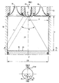
- an internal combustion engine with direct fuel injection for example of the diesel type, comprises at least one cylinder 10 of axis XX ′ and of diameter CD, a cylinder head 12 closing the cylinder in upper part, air intake means and exhaust means for the burnt gases, here respectively one or more intake valves 14, one or more exhaust valves 16, a piston 18 sliding in the cylinder 10 and connected to a crankshaft (not shown), and a fuel injector 20, preferably arranged in the axis XX 'of the cylinder, from which comes a sheet 22 of fuel jets, which, in the example shown, has a general axis coincident with that of the cylinder 10.
- the injector may be disposed in the axis XX ′, but in this case the general axis of the layer of fuel jets coming from this fuel injector is at least parallel to this axis XX '.
- the fuel injector is low angle ply type 1 and selecting a nappe angle has 1 to more than 120 ° and preferably between 40 ° and 100 °.
- the combustion chamber is delimited on one side by the cylinder head 12, on the opposite side by the upper face 24 of the piston 18 and laterally by the wall 26 of the cylinder 10.
- a lower limit position PL of the piston 18 is determined according to which the fuel jets do not touch the wall 26 of the cylinder 10 between this position and the high position of said piston.
- This lower limit position is determined by the distance F between the point of origin O of the fuel jets coming from the nozzle of the injector 20 and the upper face 24 of the piston and is equal to D ⁇ tan (a 1/2 ), where D is the radial distance between the point O of origin of the fuel jets and the wall 26 of the cylinder 10 closest to this point.
- the distance D is equal to CD / 2, where CD is the diameter of the cylinder.
- the distance F makes it possible to determine an angular position of the crankshaft, as best visible on the Figure 2, which will give a crankshaft angle ⁇ from the bottom dead center (PMB).
- this angle ⁇ it can be specified that the wall 26 of the cylinder 10 is never wetted by the fuel for all the positions of the piston 18 between 0 ° and 180 ° - ⁇ and between 180 ° + ⁇ and 360 ° of crankshaft angle, where 0 ° and 360 ° represents the angle of the crankshaft at top dead center (TDC) corresponding to a high position of the piston, 180 ° the bottom dead center (PMB) corresponding to the bottom position piston.
- TDC top dead center
- PMB bottom dead center
- the top dead center (TDC) and the bottom dead center (PMB) correspond to engine operating phases where it is desirable to inject fuel, in particular in the intake, compression or exhaust phase.
- two types of angular zones of the crankshaft deflection will be determined which each correspond to a stroke of the piston, a first type, called authorized zones, between 0 ° and 180 ° - ⁇ or between 180 + ⁇ and 360 °, and a second type, designated restrictive zone, corresponding to an angular displacement of the crankshaft between 180 ° - ⁇ and 180 ° + ⁇ .
- the piston will therefore be between its lower limit position and its position furthest from the cylinder head.
- the piston is located, it is planned to adapt the fuel injection parameters so as to inject it, either conventionally for the authorized zones, or by using specific settings of fuel injection for the restrictive zone.
- the injection settings in the restrictive zone are such that it is intended to limit the penetration of the fuel jets into the combustion chamber.
- the injection settings in the restrictive zone are provided so that the penetration of the fuel jets, considered at the extreme lateral edges of the sheet, is less than the distance separating the point of origin O of the fuel jets up to 'to the wall 26 of the cylinder 10.
- This distance is equal to D x sin (a 1/2 ), where D is a distance as defined above and corresponds, in the example described, to CD / 2
- the means of control of the injection system that usually comprise an engine, such as an engine computer, contains in its database, the lower limit position PL of the piston 18 and the crankshaft angle ⁇ which corresponds this lower limit position.
- This calculator also contains fuel injection parameters according to the authorized zones (between 0 ° and 180 ° - ⁇ or between 180 + ⁇ and 360 ° of crankshaft angle) and according to the restrictive zone (between 180 ° - ⁇ and 180 ° + ⁇ of crankshaft angle).
- this computer determines beforehand the effective position of the piston 18 in the combustion chamber.
- This position of the piston for example, will be deduced by means of an angular position sensor provided on the crankshaft which determines the crankshaft angle from the top dead center.
- the computer checks whether this angle is contained in the authorized zones or in the restrictive zone.
- this computer will give fuel injection orders to the injection system that the engine has so that it corresponds to a conventional injection process.
- the computer will modify the injection parameters, as described above, to limit the penetration of the fuel jet into the combustion chamber.
- the present invention is not limited to the example described above but encompasses all variants.
Landscapes
- Engineering & Computer Science (AREA)
- Chemical & Material Sciences (AREA)
- Combustion & Propulsion (AREA)
- Mechanical Engineering (AREA)
- General Engineering & Computer Science (AREA)
- Electrical Control Of Air Or Fuel Supplied To Internal-Combustion Engine (AREA)
- Fuel-Injection Apparatus (AREA)
- Combustion Methods Of Internal-Combustion Engines (AREA)
Applications Claiming Priority (2)
| Application Number | Priority Date | Filing Date | Title |
|---|---|---|---|
| FR0110149 | 2001-07-27 | ||
| FR0110149A FR2827913B1 (fr) | 2001-07-27 | 2001-07-27 | Procede de controle de l'injection d'un carburant pour un moteur a combustion interne a injection directe |
Publications (2)
| Publication Number | Publication Date |
|---|---|
| EP1279809A1 true EP1279809A1 (de) | 2003-01-29 |
| EP1279809B1 EP1279809B1 (de) | 2006-12-27 |
Family
ID=8866052
Family Applications (1)
| Application Number | Title | Priority Date | Filing Date |
|---|---|---|---|
| EP02291710A Expired - Lifetime EP1279809B1 (de) | 2001-07-27 | 2002-07-08 | Verfahren zur Steuerung der Brennstoffeinspritzung einer Brennkraftmaschine mit Direkteinspritzung |
Country Status (8)
| Country | Link |
|---|---|
| US (1) | US6637403B2 (de) |
| EP (1) | EP1279809B1 (de) |
| JP (1) | JP2003056390A (de) |
| KR (1) | KR20030011606A (de) |
| AT (1) | ATE349610T1 (de) |
| DE (1) | DE60217021T2 (de) |
| ES (1) | ES2278885T3 (de) |
| FR (1) | FR2827913B1 (de) |
Cited By (1)
| Publication number | Priority date | Publication date | Assignee | Title |
|---|---|---|---|---|
| KR20030011606A (ko) * | 2001-07-27 | 2003-02-11 | 앵스띠뛰 프랑세 뒤 뻬뜨롤 | 직접 분사식 내연 기관의 연료 분사 제어 방법 |
Families Citing this family (11)
| Publication number | Priority date | Publication date | Assignee | Title |
|---|---|---|---|---|
| DE10213025B4 (de) * | 2002-03-22 | 2014-02-27 | Daimler Ag | Selbstzündende Brennkraftmaschine |
| FR2837878B1 (fr) * | 2002-03-28 | 2004-05-28 | Inst Francais Du Petrole | Procede d'injection de carburant pour moteur a combustion interne a forte sensibilite d'injection et moteur utilisant un tel procede |
| EP1625140A4 (de) * | 2002-12-23 | 2008-06-18 | Dynavax Tech Corp | Verzweigte immunmodulatorische verbindungen und anwendungsverfahren dafür |
| FR2853354B1 (fr) * | 2003-04-04 | 2006-06-09 | Peugeot Citroen Automobiles Sa | Moteur a combustion interne a injection directe d'essence et a allumage commande |
| FR2853358B1 (fr) * | 2003-04-04 | 2005-05-06 | Peugeot Citroen Automobiles Sa | Moteur a combustion interne a essence et a auto-allumage |
| FR2853356B1 (fr) * | 2003-04-04 | 2006-06-30 | Peugeot Citroen Automobiles Sa | Moteur a combustion interne a essence et a allumage commande comprenant un systeme d'injection a tres haute pression |
| FR2882100B1 (fr) * | 2005-02-16 | 2010-08-20 | Inst Francais Du Petrole | Procede de controle de l'injection du carburant pour un moteur a combustion interne et moteur utilisant un tel procede |
| FR2895026B1 (fr) | 2005-12-21 | 2011-09-09 | Inst Francais Du Petrole | Procede d'injection de carburant pour moteur a combustion interne,notamment a injection directe, comportant un piston muni d'un bol avec un teton |
| JP4506844B2 (ja) * | 2008-01-25 | 2010-07-21 | トヨタ自動車株式会社 | 内燃機関 |
| FR2933449B1 (fr) * | 2008-07-03 | 2010-07-30 | Inst Francais Du Petrole | Procede pour ameliorer la vaporisation d'un carburant utlise pour un moteur a combustion interne, notamment a injection directe, en particulier a autoallumage et plus particulierement de type diesel |
| DE102021211658A1 (de) | 2021-10-15 | 2023-04-20 | Hitachi Astemo, Ltd. | Verfahren und vorrichtung zum steuern der kraftstoffeinspritzung einer brennkraftmaschine |
Citations (7)
| Publication number | Priority date | Publication date | Assignee | Title |
|---|---|---|---|---|
| JPS631710A (ja) * | 1986-06-19 | 1988-01-06 | Nippon Clean Engine Lab Co Ltd | 火花点火方式燃料噴射層状給気燃焼方式並びに多種燃料高圧縮層状燃焼機関 |
| JPH06173737A (ja) * | 1992-12-14 | 1994-06-21 | Toyota Motor Corp | 内燃機関の燃料噴射時期制御装置 |
| JPH06213030A (ja) * | 1993-01-21 | 1994-08-02 | Toyota Motor Corp | 筒内噴射式内燃機関 |
| US5363820A (en) * | 1992-08-27 | 1994-11-15 | Man Nutzfahrzeuge Ag | Combustion chamber for air compressing, self-igniting internal combustion engines |
| EP0849448A1 (de) * | 1996-12-19 | 1998-06-24 | Cummins Engine Company, Inc. | Einspritzventil mit Stumpfwinkel und Kolben mit komplementär geformter Kammer |
| DE19908454A1 (de) * | 1998-03-09 | 1999-09-23 | Hitachi Ltd | Brennkraftmaschine mit Kompressionszündung sowie Verfahren für ihre Steuerung |
| US6053144A (en) * | 1998-11-05 | 2000-04-25 | Caterpillar Inc. | Diesel engine with a combustor which provides combustion products to reduce NOx production in a combustion chamber |
Family Cites Families (11)
| Publication number | Priority date | Publication date | Assignee | Title |
|---|---|---|---|---|
| US4446830A (en) * | 1983-01-10 | 1984-05-08 | Ford Motor Company | Method of operating an engine with a high heat of vaporization fuel |
| JPH04228850A (ja) * | 1990-12-27 | 1992-08-18 | Toyota Motor Corp | 筒内噴射式内燃機関 |
| JPH05248244A (ja) * | 1992-03-10 | 1993-09-24 | Toyota Motor Corp | 筒内噴射式内燃機関 |
| JPH08177684A (ja) * | 1994-12-26 | 1996-07-12 | Hitachi Ltd | 燃料噴射弁、及びこれを備えた内燃機関装置 |
| JPH07324661A (ja) * | 1994-05-30 | 1995-12-12 | Mitsubishi Motors Corp | 直接噴射式ディーゼルエンジンの燃料噴射方法及び燃料噴射ノズル |
| WO1996036808A1 (fr) * | 1995-05-16 | 1996-11-21 | Mitsubishi Jidosha Kogyo Kabushiki Kaisha | Moteur a combustion interne de type a injection dans le cylindre |
| US5720253A (en) * | 1995-09-11 | 1998-02-24 | Nissan Motor Co., Ltd. | Direct-injection type spark-ignition internal combustion engine |
| US6148792A (en) * | 1997-02-01 | 2000-11-21 | Ford Global Technologies, Inc. | Direct injection spark ignition engine |
| US6267096B1 (en) * | 2000-01-07 | 2001-07-31 | Ford Global Technologies, Inc. | Three-valve cylinder head system |
| FR2827913B1 (fr) * | 2001-07-27 | 2003-09-19 | Inst Francais Du Petrole | Procede de controle de l'injection d'un carburant pour un moteur a combustion interne a injection directe |
| JP2003113716A (ja) * | 2001-10-03 | 2003-04-18 | Nissan Motor Co Ltd | 筒内直接燃料噴射式火花点火エンジン |
-
2001
- 2001-07-27 FR FR0110149A patent/FR2827913B1/fr not_active Expired - Fee Related
-
2002
- 2002-07-08 AT AT02291710T patent/ATE349610T1/de not_active IP Right Cessation
- 2002-07-08 DE DE60217021T patent/DE60217021T2/de not_active Expired - Lifetime
- 2002-07-08 EP EP02291710A patent/EP1279809B1/de not_active Expired - Lifetime
- 2002-07-08 ES ES02291710T patent/ES2278885T3/es not_active Expired - Lifetime
- 2002-07-23 KR KR1020020043187A patent/KR20030011606A/ko not_active Application Discontinuation
- 2002-07-23 US US10/200,198 patent/US6637403B2/en not_active Expired - Fee Related
- 2002-07-26 JP JP2002217804A patent/JP2003056390A/ja active Pending
Patent Citations (7)
| Publication number | Priority date | Publication date | Assignee | Title |
|---|---|---|---|---|
| JPS631710A (ja) * | 1986-06-19 | 1988-01-06 | Nippon Clean Engine Lab Co Ltd | 火花点火方式燃料噴射層状給気燃焼方式並びに多種燃料高圧縮層状燃焼機関 |
| US5363820A (en) * | 1992-08-27 | 1994-11-15 | Man Nutzfahrzeuge Ag | Combustion chamber for air compressing, self-igniting internal combustion engines |
| JPH06173737A (ja) * | 1992-12-14 | 1994-06-21 | Toyota Motor Corp | 内燃機関の燃料噴射時期制御装置 |
| JPH06213030A (ja) * | 1993-01-21 | 1994-08-02 | Toyota Motor Corp | 筒内噴射式内燃機関 |
| EP0849448A1 (de) * | 1996-12-19 | 1998-06-24 | Cummins Engine Company, Inc. | Einspritzventil mit Stumpfwinkel und Kolben mit komplementär geformter Kammer |
| DE19908454A1 (de) * | 1998-03-09 | 1999-09-23 | Hitachi Ltd | Brennkraftmaschine mit Kompressionszündung sowie Verfahren für ihre Steuerung |
| US6053144A (en) * | 1998-11-05 | 2000-04-25 | Caterpillar Inc. | Diesel engine with a combustor which provides combustion products to reduce NOx production in a combustion chamber |
Non-Patent Citations (3)
| Title |
|---|
| PATENT ABSTRACTS OF JAPAN vol. 012, no. 195 (M - 705) 7 June 1988 (1988-06-07) * |
| PATENT ABSTRACTS OF JAPAN vol. 018, no. 512 (M - 1679) 27 September 1994 (1994-09-27) * |
| PATENT ABSTRACTS OF JAPAN vol. 018, no. 579 (M - 1698) 7 November 1994 (1994-11-07) * |
Cited By (1)
| Publication number | Priority date | Publication date | Assignee | Title |
|---|---|---|---|---|
| KR20030011606A (ko) * | 2001-07-27 | 2003-02-11 | 앵스띠뛰 프랑세 뒤 뻬뜨롤 | 직접 분사식 내연 기관의 연료 분사 제어 방법 |
Also Published As
| Publication number | Publication date |
|---|---|
| US6637403B2 (en) | 2003-10-28 |
| KR20030011606A (ko) | 2003-02-11 |
| DE60217021T2 (de) | 2007-07-12 |
| ATE349610T1 (de) | 2007-01-15 |
| FR2827913A1 (fr) | 2003-01-31 |
| EP1279809B1 (de) | 2006-12-27 |
| JP2003056390A (ja) | 2003-02-26 |
| DE60217021D1 (de) | 2007-02-08 |
| ES2278885T3 (es) | 2007-08-16 |
| FR2827913B1 (fr) | 2003-09-19 |
| US20030019466A1 (en) | 2003-01-30 |
Similar Documents
| Publication | Publication Date | Title |
|---|---|---|
| EP1217186B1 (de) | Direkteinspritzbrennkraftmaschine mit kleinem Sprühwinkel und Verfahren zu ihrer Verwendung | |
| EP1726805B1 (de) | Verfahren zur Steuerung der Spülung eines insbesondere aufgeladenen Motors mit Saugroheinspritzung und ein ein solches Verfahren verwendender Motor | |
| EP1801398B1 (de) | Verfahren zur Einspritzung von Kraftstoff für Verbrennungsmotoren, insbesondere mit Direkteinspritzung, umfassend einen Kolben, der mit einer Mulde mit einem Zentrierstift ausgestattet ist | |
| EP1279809B1 (de) | Verfahren zur Steuerung der Brennstoffeinspritzung einer Brennkraftmaschine mit Direkteinspritzung | |
| WO2007042674A1 (fr) | Procede de contrôle de l'auto-inflammation d'un melange carbure, notamment pour moteur a combustion interne de type diesel, et moteur utilisant un tel procede | |
| FR2818325A1 (fr) | Moteur a injection directe pourvu d'un faible angle de nappe et procedes permettant d'utiliser un tel moteur | |
| EP1344914B1 (de) | Brennkraftmaschine mit Brennstoffeinspritzeinrichtung | |
| EP1340891B1 (de) | Verfahren und Verbrennungsmotor zur gesicherten Mischung von zumindest einem gasförmigen Fluid, wie Luft, und einem Brennstoff in einer Brennkammer einer direkteinspritzenden Brennkraftmaschine | |
| EP3673165B1 (de) | Verfahren zum betrieb einer brennkraftmaschine nach thermodynamischen bedingungen in der einlass- und abgasleitung | |
| EP1348847B1 (de) | Verfahren zur Brennstoffeinspritzung für eine Brennkraftmaschine mit Einspritzung hoher Sensibilität und Motor der ein solches Verfahren verwendet | |
| EP1861596B1 (de) | Brennkraftmaschine mit direkteinspritzung und eine omega-formige kolbenmulde | |
| EP1279802B1 (de) | Verbrennungsregelung für eine Brennkraftmaschine | |
| FR2918704A3 (fr) | Procede de levees de soupapes pour la preparation d'un melange air-carburant lors du demarrage a froid d'un moteur a combustion interne | |
| EP1769148B1 (de) | Verbessertes verfahren zur steuerung eines verbrennungsmotors mit dem ziel der reduzierung der verschmutzenden emissionen, motor der nach diesem verfahren arbeitet, und kraftfahrzeug mit genanntem motor | |
| FR2818324A1 (fr) | Moteur a injection directe, pourvu d'un injecteur a faible angle de nappe | |
| FR2853358A1 (fr) | Moteur a combustion interne a essence et a auto-allumage | |
| FR2878906A1 (fr) | Moteur a injection directe de carburant avec un piston comportant un bol presentant une paroi laterale inclinee | |
| EP1859133A1 (de) | Kraftstoffeinspritzsteuerverfahren für einen brennkraftmotor und ein solches verfahren einsetzender motor | |
| FR2756589A1 (fr) | Moteur a combustion interne a allumage par compression et a injection directe | |
| FR2910539A1 (fr) | Agencement de l'element de chauffage d'une bougie de prechauffage dans une chambre de combustion | |
| FR2925115A1 (fr) | Moteur a combustion interne a injection directe de carburant et procede pour realiser un melange carbure utilise pour ce moteur | |
| FR2895456A1 (fr) | Procede d'injection de carburant dans un moteur pour augmenter les performances a pleine charge du moteur | |
| EP1241332A1 (de) | Brennkammerdach | |
| FR2857407A1 (fr) | Procede d'actionnement d'un moteur a allumage par etincelles a injection directe, et moteur a allumage par etincelles a injection directe |
Legal Events
| Date | Code | Title | Description |
|---|---|---|---|
| PUAI | Public reference made under article 153(3) epc to a published international application that has entered the european phase |
Free format text: ORIGINAL CODE: 0009012 |
|
| AK | Designated contracting states |
Designated state(s): AT BE BG CH CY CZ DE DK EE ES FI FR GB GR IE IT LI LU MC NL PT SE SK TR |
|
| AX | Request for extension of the european patent |
Extension state: AL LT LV MK RO SI |
|
| 17P | Request for examination filed |
Effective date: 20030729 |
|
| AKX | Designation fees paid |
Designated state(s): AT BE BG CH CY CZ DE DK EE ES FI FR GB GR IE IT LI LU MC NL PT SE SK TR |
|
| GRAP | Despatch of communication of intention to grant a patent |
Free format text: ORIGINAL CODE: EPIDOSNIGR1 |
|
| GRAS | Grant fee paid |
Free format text: ORIGINAL CODE: EPIDOSNIGR3 |
|
| GRAA | (expected) grant |
Free format text: ORIGINAL CODE: 0009210 |
|
| AK | Designated contracting states |
Kind code of ref document: B1 Designated state(s): AT BE BG CH CY CZ DE DK EE ES FI FR GB GR IE IT LI LU MC NL PT SE SK TR |
|
| PG25 | Lapsed in a contracting state [announced via postgrant information from national office to epo] |
Ref country code: FI Free format text: LAPSE BECAUSE OF FAILURE TO SUBMIT A TRANSLATION OF THE DESCRIPTION OR TO PAY THE FEE WITHIN THE PRESCRIBED TIME-LIMIT Effective date: 20061227 Ref country code: DK Free format text: LAPSE BECAUSE OF FAILURE TO SUBMIT A TRANSLATION OF THE DESCRIPTION OR TO PAY THE FEE WITHIN THE PRESCRIBED TIME-LIMIT Effective date: 20061227 Ref country code: NL Free format text: LAPSE BECAUSE OF FAILURE TO SUBMIT A TRANSLATION OF THE DESCRIPTION OR TO PAY THE FEE WITHIN THE PRESCRIBED TIME-LIMIT Effective date: 20061227 Ref country code: CZ Free format text: LAPSE BECAUSE OF FAILURE TO SUBMIT A TRANSLATION OF THE DESCRIPTION OR TO PAY THE FEE WITHIN THE PRESCRIBED TIME-LIMIT Effective date: 20061227 Ref country code: SK Free format text: LAPSE BECAUSE OF FAILURE TO SUBMIT A TRANSLATION OF THE DESCRIPTION OR TO PAY THE FEE WITHIN THE PRESCRIBED TIME-LIMIT Effective date: 20061227 Ref country code: AT Free format text: LAPSE BECAUSE OF FAILURE TO SUBMIT A TRANSLATION OF THE DESCRIPTION OR TO PAY THE FEE WITHIN THE PRESCRIBED TIME-LIMIT Effective date: 20061227 Ref country code: IE Free format text: LAPSE BECAUSE OF FAILURE TO SUBMIT A TRANSLATION OF THE DESCRIPTION OR TO PAY THE FEE WITHIN THE PRESCRIBED TIME-LIMIT Effective date: 20061227 |
|
| REG | Reference to a national code |
Ref country code: GB Ref legal event code: FG4D Free format text: NOT ENGLISH |
|
| REG | Reference to a national code |
Ref country code: IE Ref legal event code: FG4D Free format text: LANGUAGE OF EP DOCUMENT: FRENCH |
|
| REF | Corresponds to: |
Ref document number: 60217021 Country of ref document: DE Date of ref document: 20070208 Kind code of ref document: P |
|
| PG25 | Lapsed in a contracting state [announced via postgrant information from national office to epo] |
Ref country code: BG Free format text: LAPSE BECAUSE OF FAILURE TO SUBMIT A TRANSLATION OF THE DESCRIPTION OR TO PAY THE FEE WITHIN THE PRESCRIBED TIME-LIMIT Effective date: 20070327 Ref country code: SE Free format text: LAPSE BECAUSE OF FAILURE TO SUBMIT A TRANSLATION OF THE DESCRIPTION OR TO PAY THE FEE WITHIN THE PRESCRIBED TIME-LIMIT Effective date: 20070327 |
|
| GBT | Gb: translation of ep patent filed (gb section 77(6)(a)/1977) |
Effective date: 20070404 |
|
| PG25 | Lapsed in a contracting state [announced via postgrant information from national office to epo] |
Ref country code: PT Free format text: LAPSE BECAUSE OF FAILURE TO SUBMIT A TRANSLATION OF THE DESCRIPTION OR TO PAY THE FEE WITHIN THE PRESCRIBED TIME-LIMIT Effective date: 20070528 |
|
| NLV1 | Nl: lapsed or annulled due to failure to fulfill the requirements of art. 29p and 29m of the patents act | ||
| REG | Reference to a national code |
Ref country code: ES Ref legal event code: FG2A Ref document number: 2278885 Country of ref document: ES Kind code of ref document: T3 |
|
| REG | Reference to a national code |
Ref country code: IE Ref legal event code: FD4D |
|
| PLBE | No opposition filed within time limit |
Free format text: ORIGINAL CODE: 0009261 |
|
| STAA | Information on the status of an ep patent application or granted ep patent |
Free format text: STATUS: NO OPPOSITION FILED WITHIN TIME LIMIT |
|
| 26N | No opposition filed |
Effective date: 20070928 |
|
| BERE | Be: lapsed |
Owner name: INSTITUT FRANCAIS DU PETROLE Effective date: 20070731 |
|
| REG | Reference to a national code |
Ref country code: CH Ref legal event code: PL |
|
| PG25 | Lapsed in a contracting state [announced via postgrant information from national office to epo] |
Ref country code: LI Free format text: LAPSE BECAUSE OF NON-PAYMENT OF DUE FEES Effective date: 20070731 Ref country code: MC Free format text: LAPSE BECAUSE OF NON-PAYMENT OF DUE FEES Effective date: 20070731 Ref country code: CH Free format text: LAPSE BECAUSE OF NON-PAYMENT OF DUE FEES Effective date: 20070731 Ref country code: GR Free format text: LAPSE BECAUSE OF FAILURE TO SUBMIT A TRANSLATION OF THE DESCRIPTION OR TO PAY THE FEE WITHIN THE PRESCRIBED TIME-LIMIT Effective date: 20070328 |
|
| REG | Reference to a national code |
Ref country code: FR Ref legal event code: ST Effective date: 20080331 |
|
| PG25 | Lapsed in a contracting state [announced via postgrant information from national office to epo] |
Ref country code: BE Free format text: LAPSE BECAUSE OF NON-PAYMENT OF DUE FEES Effective date: 20070731 |
|
| PG25 | Lapsed in a contracting state [announced via postgrant information from national office to epo] |
Ref country code: FR Free format text: LAPSE BECAUSE OF NON-PAYMENT OF DUE FEES Effective date: 20070731 |
|
| PGFP | Annual fee paid to national office [announced via postgrant information from national office to epo] |
Ref country code: ES Payment date: 20080717 Year of fee payment: 7 |
|
| PG25 | Lapsed in a contracting state [announced via postgrant information from national office to epo] |
Ref country code: EE Free format text: LAPSE BECAUSE OF FAILURE TO SUBMIT A TRANSLATION OF THE DESCRIPTION OR TO PAY THE FEE WITHIN THE PRESCRIBED TIME-LIMIT Effective date: 20061227 |
|
| PG25 | Lapsed in a contracting state [announced via postgrant information from national office to epo] |
Ref country code: LU Free format text: LAPSE BECAUSE OF NON-PAYMENT OF DUE FEES Effective date: 20070708 Ref country code: CY Free format text: LAPSE BECAUSE OF FAILURE TO SUBMIT A TRANSLATION OF THE DESCRIPTION OR TO PAY THE FEE WITHIN THE PRESCRIBED TIME-LIMIT Effective date: 20061227 |
|
| PG25 | Lapsed in a contracting state [announced via postgrant information from national office to epo] |
Ref country code: TR Free format text: LAPSE BECAUSE OF FAILURE TO SUBMIT A TRANSLATION OF THE DESCRIPTION OR TO PAY THE FEE WITHIN THE PRESCRIBED TIME-LIMIT Effective date: 20061227 |
|
| REG | Reference to a national code |
Ref country code: ES Ref legal event code: FD2A Effective date: 20090709 |
|
| PG25 | Lapsed in a contracting state [announced via postgrant information from national office to epo] |
Ref country code: ES Free format text: LAPSE BECAUSE OF NON-PAYMENT OF DUE FEES Effective date: 20090709 |
|
| REG | Reference to a national code |
Ref country code: DE Ref legal event code: R081 Ref document number: 60217021 Country of ref document: DE Owner name: IFP ENERGIES NOUVELLES, FR Free format text: FORMER OWNER: INSTITUT FRANCAIS DU PETROLE, RUEIL-MALMAISON, HAUTS-DE-SEINE, FR Effective date: 20110331 |
|
| PGFP | Annual fee paid to national office [announced via postgrant information from national office to epo] |
Ref country code: GB Payment date: 20110719 Year of fee payment: 10 |
|
| GBPC | Gb: european patent ceased through non-payment of renewal fee |
Effective date: 20120708 |
|
| PG25 | Lapsed in a contracting state [announced via postgrant information from national office to epo] |
Ref country code: GB Free format text: LAPSE BECAUSE OF NON-PAYMENT OF DUE FEES Effective date: 20120708 |
|
| PGFP | Annual fee paid to national office [announced via postgrant information from national office to epo] |
Ref country code: DE Payment date: 20130723 Year of fee payment: 12 |
|
| PGFP | Annual fee paid to national office [announced via postgrant information from national office to epo] |
Ref country code: IT Payment date: 20130724 Year of fee payment: 12 |
|
| REG | Reference to a national code |
Ref country code: DE Ref legal event code: R119 Ref document number: 60217021 Country of ref document: DE |
|
| PG25 | Lapsed in a contracting state [announced via postgrant information from national office to epo] |
Ref country code: IT Free format text: LAPSE BECAUSE OF NON-PAYMENT OF DUE FEES Effective date: 20140708 Ref country code: DE Free format text: LAPSE BECAUSE OF NON-PAYMENT OF DUE FEES Effective date: 20150203 |
|
| REG | Reference to a national code |
Ref country code: DE Ref legal event code: R119 Ref document number: 60217021 Country of ref document: DE Effective date: 20150203 |