EP1279217B1 - Electrodynamic machine - Google Patents
Electrodynamic machine Download PDFInfo
- Publication number
- EP1279217B1 EP1279217B1 EP00940039A EP00940039A EP1279217B1 EP 1279217 B1 EP1279217 B1 EP 1279217B1 EP 00940039 A EP00940039 A EP 00940039A EP 00940039 A EP00940039 A EP 00940039A EP 1279217 B1 EP1279217 B1 EP 1279217B1
- Authority
- EP
- European Patent Office
- Prior art keywords
- shaft
- rotor
- electrodynamic machine
- machine according
- rotors
- Prior art date
- Legal status (The legal status is an assumption and is not a legal conclusion. Google has not performed a legal analysis and makes no representation as to the accuracy of the status listed.)
- Expired - Lifetime
Links
- 230000005520 electrodynamics Effects 0.000 title claims abstract description 29
- 239000004020 conductor Substances 0.000 claims description 9
- 238000010276 construction Methods 0.000 claims description 4
- 230000003993 interaction Effects 0.000 claims description 4
- 230000000694 effects Effects 0.000 claims description 3
- 230000007246 mechanism Effects 0.000 description 10
- 230000008901 benefit Effects 0.000 description 5
- XEEYBQQBJWHFJM-UHFFFAOYSA-N Iron Chemical compound [Fe] XEEYBQQBJWHFJM-UHFFFAOYSA-N 0.000 description 4
- 230000008844 regulatory mechanism Effects 0.000 description 3
- 238000004804 winding Methods 0.000 description 3
- 229910052742 iron Inorganic materials 0.000 description 2
- 230000005540 biological transmission Effects 0.000 description 1
- 230000007717 exclusion Effects 0.000 description 1
- 238000009434 installation Methods 0.000 description 1
- 238000003466 welding Methods 0.000 description 1
Images


Classifications
-
- H—ELECTRICITY
- H02—GENERATION; CONVERSION OR DISTRIBUTION OF ELECTRIC POWER
- H02K—DYNAMO-ELECTRIC MACHINES
- H02K16/00—Machines with more than one rotor or stator
- H02K16/005—Machines with only rotors, e.g. counter-rotating rotors
Definitions
- This invention relates to an electrodynamic machine such as an electric generator or an electric motor.
- the invention has been devised as an electrodynamic machine for generating an electrical current, although it may also be used as an electric motor.
- an electrodynamic machine comprises two parts, being a stator and a rotor, one of which incorporates a magnet (which can be either a permanent magnet or an electro-magnet) and the other of which incorporates a conductor.
- a magnet which can be either a permanent magnet or an electro-magnet
- a conductor In the case of an electric generator, relative movement between the rotor and the stator generates an electrical current in the conductor.
- an electric motor the passage of an electric current through the conductor induces rotation of the rotor relative to the stator. Examples of such arrangements may be seen In FR 2 766 989 ; US 2 762 939 ; US 5 675 203 ; EP 0 817 359 ; and GB 991897 .
- the present invention utilises two parts which rotate relative to each other but neither of those parts is stationary during such relative movement in the sense of a conventional stator.
- the invention provides an electrodynamic machine comprising an inner rotor, an outer rotor disposed around the inner motor for interaction therewith, the inner rotor being mounted on a shaft for rotation therewith, the outer motor being mounted for rotation about the shaft and a drive means for rotating the inner and outer rotors, relative to each other, the drive means comprises a drive shaft, a drive pinion connected to the drive shaft for rotation therewith, and first and second driven pinions in meshing engagement with the drive pinion, the first pinion being connected to the outer rotor for rotation therewith and second driven pinion being connected to the shaft for rotation therewith to effect rotation of the inner rotor.
- the inner and outer rotors rotate in opposite directions.
- the first and second rotors may alternatively rotate in a common direction but at different rotational speeds so as to provide the relative rotation therebetween.
- the electrodynamic machine is an electric generator
- relative movement between the two rotors generates an electrical current.
- one rotor provides a magnetic field which may be established by either a permanent magnet or an electromagnet.
- the other rotor provides a conductor in which the electric current is generated upon movement of the conductor through the magnetic field.
- Any suitable structure such as a commutator or a slip ring arrangement may be provided for transferring current from the conductor.
- an air gap is defined therebetween.
- the two rotors may be positioned in an axially spaced relationship with an air gap defined therebetween.
- the invention has been devised particularly, although not solely, for use with an engine means as disclosed in Australian Provisional Patent Application Nos. PQ4601 and PQ4700. Certain embodiments of that engine means have two output shafts which are adapted to rotate in opposite directions and which are operatively connected to an elecrodynamic machine for generating electrical current.
- the electrodynamic machine driven by the engine means can be an electrodynamic machine according to the present invention.
- the invention also provides a combination of an engine means and an electric generator adapted to be driven by the engine means, the engine means having a first output shaft and a second output shaft, the electric generator having a first rotor and a second rotor, the first rotor being drivingly connected to the first output shaft of the engine and the second rotor being drivingly connected to the second output shaft of the engine, the first and second rotors being adapted to rotate relative to each other thereby to cause generation of the an electric current.
- an electrodynamic machine 10 in the form of an electric generator for generating an electrical current which can be either a DC current or an AC current. Accordingly, the electric generator 10 can function as any appropriate form of generator such as a dynamo or an alternator.
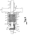
- the electric generator 10 comprises a first shaft 11 and a second shaft 12.
- the two shafts 11, 12 are supported in bearings 9.
- a first rotor 13 is mounted on the first shaft 11 and a second rotor 15 is mounted on the second shaft 12.
- the two shafts 11, 12 are connected to a drive means 14 which operates to drive the shafts in opposite directions and thereby cause the first and second rotors 13, 15 to rotate one relative to the other in opposite directions.
- the two rotors 13, 15 are positioned one within the other, with an air gap 17 defined therebetween. Accordingly, the first rotor 13 constitutes an outer rotor and the second rotor 15 constitutes an inner rotor.
- the first (outer) rotor 13 is rotatably supported on the second (inner) rotor 15 by bearings 18.
- the two rotors 13, 15 are adapted to co-operate to generate an electrical current.
- the inner rotor 15 incorporates a conductor defined by a series of windings 19 which are connected to a slip ring system 21.
- the construction of the outer rotor 13 is similar to that of a stator in a conventional electric generator
- the construction of the inner rotor 15 is similar to a rotor in a conventional electric generator.
- relative rotation between the rotor and the stator generates an electrical current.
- a similar result is achieved in the present embodiment whereby relative rotation between the two rotors 13, 15 generates an electrical current which is extracted by way of the slip ring system 21 in known manner.
- the two shafts 11, 12 are connected together in a manner which provides mutual lateral support while allowing relative rotation therebetween.
- the shaft 11 incorporates a socket 25 which receives a spigot 27 provided on the second shaft 12.
- the second shaft is actually formed In two sections 12a and 12b, with the inner rotor 15 being positioned between the two sections.
- the second section 12b provides the spigot 27, as best seen in Figure 3 of the drawings.
- the outer rotor 13 is of hollow construction comprising a cylindrical side wall 30 and two end walls 31, 32.
- the end wall 32 is detachably mounted on the cylindrical side wall 30 to facilitate removal for access to the interior region defined within the hollow outer rotor 13 to facilitate installation and removal of the inner rotor 15.
- the drive means 14 in this embodiment comprises an input drive shaft 33 which is drivingly connected to a motor (not shown).
- a drive pinion 34 is mounted on the input drive shaft 33 for rotation therewith.
- the drive pinion 34 is in meshing engagement with a first driven pinion 35 and a second driven pinion 36.
- the second driven pinion 36 is mounted on the second drive shaft 12 for transmission of rotational torque from the input drive shaft 33 to the second drive shaft 12.
- the first driven pinion 35 is drivingly connected to the outer rotor 13. More particularly, the first driven pinion 35 is mounted on the end wall 32 of the outer rotor 13 and is rigidly secured thereto by suitable fixings or by welding.
- the first driven pinion 35 is not connected to the second shaft 12 but merely surrounds the second shaft without being drivingly connected thereto. This is accomplished by the second shaft 12 passing freely through a central passage within the first driven pinion 35.
- the input driving shaft 33 is drivingly connected to the first and second rotors 13, 15 so as to cause relative rotation therebetween In opposite directions.
- the input drive shaft 33 is drivingly connected to the first rotor 13 through the drive pinion 34 and the first driven pinion 35 which is in meshing engagement with the drive pinion 34 and which is drivingly connected to the first rotor 13.
- the driving input shaft 33 is drivingly connected to the second rotor 15 through the drive pinion 34 which is drivingly connected to the second driven pinion 36 which is in turn drivingly connected to the second drive shaft 12 which is in turn drivingly connected to the inner rotor 15.
- a fly wheel 37 is mounted on the first shaft 11 provided for the purpose of maintaining reasonably constant rotational speeds for the rotors 13, 15 in spite of any minor variations in the input power delivered by the motor (not shown) driving the shaft 33.
- the slip ring system 21 is conveniently located on the first shaft 11 adjacent the fly wheel 37.
- the drive means 14 has several advantages, one of which is that it ensures that the rotors 13, 15 rotate at the same angular velocity (although in opposite directions) by virtue of the drive pinion 34 being in meshing engagement with both of the driven pinions 35, 36.
- the drive means 14 provide the additional benefit that the two shafts 11, 12 undergo rotation and can be used to deliver rotational torque for other purposes.
- the engine (not shown) for driving the electric generator can be connected to the second shaft12, with the shaft 33 as well as the shaft 11 both functioning as output shafts for delivering rotational torque for other purposes.
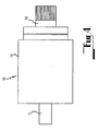
- the electric generator 10 according to the second embodiment comprises a first shaft 11 and a second shaft 12.
- a first rotor 13 is mounted on the first shaft 11 and the second rotor 15 is mounted on the second shaft 12.
- each shaft 11, 12 is adapted to be connected to a respective drive means (not shown) such as an engine.
- the electric generator 10 according to this embodiment operates in a similar fashion to the electric generator of the first embodiment in the sense that rotational torque is applied to the first shaft 11 and the second shaft 12 in opposite directions so as to cause the first and second rotors 13, 15 to also rotate one relative to the other in opposite directions.
- a speed regulations means may be used in association with the electric generator.
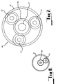
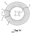
- This electric generator 10 incorporates a speed regulation means 40 comprising a gear mechanism 41 in the form of an epicyclic gear train 45 having an internal gear 47 mounted on or formed integrally with the outer rotor 13 and a sun gear 49 mounted on the second shaft 12, with a series of planetary gears 51 in meshing engagement between the Internal gear 47 and the sun gear 49.
- the epicyclic gear train 45 provides a geared connection between the first shaft 11 and the second shaft 12, thereby ensuring that the two drive shafts rotate at a common angular velocity (although of course in opposite directions).
- FIG. 8 of the drawings illustrates a further speed control means 40 which is similar to the speed control means illustrated in Figures 6 and 7 with the exception that only one planetary gear is utilised.
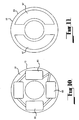
- the electric generator 10 comprises a first shaft 11 on which a first rotor 13 is mounted, and a second shaft 12 on which a second rotor 15 is mounted.
- the two rotors 13, 15 are not mounted one within the other as was the case with the first embodiment but rather positioned axially in a side-by-side relationship with an air gap 17 defined therebetween.
- the two shafts 11, 12 are connected one to another in a manner which provides mutual lateral support while allowing relative rotation therebetween. This is achieved by the provision of a socket 25 in one of the shafts receiving a spigot 27 on the other of the shafts.
- the first rotor 13 has an end face 61 which confronts the air gap 17 and the second rotor 15 has an end face 63 which also confronts the air gap 17.
- the end face 61 incorporates winding coils 65 and the face 63 incorporates magnetic iron 67, the arrangement being such that relative rotation between the two rotors causes interaction between the winding coils and magnetic iron so as to generate an electrical current.
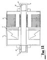
- FIG. 12 and 13 of the accompanying drawings there is shown an electric generator not according to the present invention.
- the electric generator is somewhat similar to the electric generator of Figures 9 , 10 and 11 inasmuch as the two rotors 13, 15 are mounted axially with respect to each other with an air gap 17 defined therebetween.
- the two rotors 13, 15 are mounted on a common axle shaft 81.
- the ends of the axle shaft 81 are received in sockets 82 provided in the corresponding ends of the first drive shaft 11 and the second drive shafts 12.
- This arrangement provides mutual support for the two shafts 11, 12 through the axle shaft 81 while allowing relative rotation between those two shafts and, of course the two rotors 13, 15.
- the first shaft 11 is of course drivingly connected to the first rotor 13 and the second shaft 12 is drivingly connected to the second rotor 15.
- a slip ring system 21 is provided for extracting current generated by relative rotation between the two rotors 13, 15.
- an electric generator 10 adapted to be drawn by two engines (not shown), one engine having output shaft 97 and the other engine having output shaft 99.
- the two output shafts 97, 99 are drivingly connected to the two shafts 11, 12 of the electric generator 10 through a gear mechanism 90.
- the gear mechanism 90 comprises a first bevel pinion 93 mounted on output shaft 97 and a second bevel pinion 95 mounted on the output shaft 99.
- the two bevel pinions 93, 95 are in meshing engagement with a first bevel gear 91 and a second bevel gear 92.
- the two bevel gears 91, 92 are in spaced apart relationship and rotate about a common axis.
- the first bevel gear 91 is mounted on the outer rotor 13 and so is drivingly connected to the first shaft 11.
- the second bevel gear 92 is drivingly connected to the second shaft 12 by being mounted thereon.
- the meshing engagement between the pinions 93, 95 and gears 91, 92 ensures that the two roors 13, 15 rotate at the same angular velocity but in opposite directions.
- the gear mechanism 101 comprises a bevel pinion 105 mounted on the output shaft 103.
- the bevel pinion 105 is in meshing engagement with a first bevel gear 107 and a second bevel gear 109.
- the two bevel gears 107, 109 are in spaced relationship and rotate about a common axis.
- the first bevel gear 107 is mounted on the outer rotor 13 of the electric generator 10 and so is drivingly connected to the first shaft 11.
- the second bevel gear 109 is drivingly connected to the second shaft 12 by being mounted thereon.
- the meshing engagement between the pinion 105 and the two bevel gears 107, 109 ensures that the two rotors 13, 15 rotate at the same angular velocity but in opposite directions.
- the present invention provides a simple yet highly effective electrodynamic machine which incorporates two rotors rotating one relative to the other.
- the electrodynamic machine may function as an electric motor whereby electrical energy delivered to the electrodynamic machine Is converted into mechanical energy in the form of rotational torque delivered to the drive shafts of the two rotors.
Landscapes
- Engineering & Computer Science (AREA)
- Power Engineering (AREA)
- Connection Of Motors, Electrical Generators, Mechanical Devices, And The Like (AREA)
- Iron Core Of Rotating Electric Machines (AREA)
- Reciprocating, Oscillating Or Vibrating Motors (AREA)
Applications Claiming Priority (3)
| Application Number | Priority Date | Filing Date | Title |
|---|---|---|---|
| AUPQ611700 | 2000-03-09 | ||
| AUPQ6117A AUPQ611700A0 (en) | 2000-03-09 | 2000-03-09 | Electrodynamic machine |
| PCT/AU2000/000778 WO2001067584A1 (en) | 2000-03-09 | 2000-06-29 | Electrodynamic machine |
Publications (3)
| Publication Number | Publication Date |
|---|---|
| EP1279217A1 EP1279217A1 (en) | 2003-01-29 |
| EP1279217A4 EP1279217A4 (en) | 2003-09-03 |
| EP1279217B1 true EP1279217B1 (en) | 2011-03-16 |
Family
ID=3820220
Family Applications (1)
| Application Number | Title | Priority Date | Filing Date |
|---|---|---|---|
| EP00940039A Expired - Lifetime EP1279217B1 (en) | 2000-03-09 | 2000-06-29 | Electrodynamic machine |
Country Status (13)
| Country | Link |
|---|---|
| US (2) | US20050104466A1 (enExample) |
| EP (1) | EP1279217B1 (enExample) |
| JP (1) | JP2003527053A (enExample) |
| CN (1) | CN1242533C (enExample) |
| AT (1) | ATE502430T1 (enExample) |
| AU (3) | AUPQ611700A0 (enExample) |
| DE (1) | DE60045743D1 (enExample) |
| DK (1) | DK1279217T3 (enExample) |
| ES (1) | ES2464871T3 (enExample) |
| NZ (1) | NZ521648A (enExample) |
| PT (1) | PT1279217E (enExample) |
| WO (1) | WO2001067584A1 (enExample) |
| ZA (1) | ZA200208058B (enExample) |
Families Citing this family (17)
| Publication number | Priority date | Publication date | Assignee | Title |
|---|---|---|---|---|
| CN102047532A (zh) * | 2008-04-07 | 2011-05-04 | 埃内吉斯特罗公司 | 含有飞轮的能量存储装置 |
| US8063528B2 (en) * | 2009-12-18 | 2011-11-22 | General Electric Company | Counter-rotatable generator |
| DE102010035088A1 (de) * | 2010-08-21 | 2012-03-08 | Audi Ag | Radaufhängung für ein Kraftfahrzeug |
| ITRM20100522A1 (it) * | 2010-10-06 | 2012-04-07 | Giacomo Carlucci | "generatore elettrico con statore rotante" |
| US8531072B2 (en) * | 2011-02-16 | 2013-09-10 | E-Wish Technology, Llc | Dual-mode counter-rotating-to-traditional electric motor and system |
| EP2629407B1 (en) * | 2012-02-17 | 2014-12-24 | Bell Helicopter Textron Inc. | Electrical generator for rotating structure |
| TWI461618B (zh) * | 2012-03-06 | 2014-11-21 | Yu Chi Wang | 同軸風力發電機、電動機及通風系統 |
| US9331535B1 (en) | 2012-03-08 | 2016-05-03 | Leidos, Inc. | Radial flux alternator |
| EP2869441A4 (en) * | 2012-06-28 | 2016-06-29 | Yuchi Wang | COAXIAL WIND TURBINE, ENGINE AND VENTILATION SYSTEM |
| CN104785849A (zh) * | 2015-04-20 | 2015-07-22 | 禹伟 | 一种卧式双刃剪切机传送带驱动组件 |
| CN108233605A (zh) * | 2016-12-15 | 2018-06-29 | 佛山市净瓶泉卫浴有限公司 | 一种无反作用力电机及发电装置 |
| CN108233604A (zh) * | 2016-12-15 | 2018-06-29 | 佛山市净瓶泉卫浴有限公司 | 一种驱动设备 |
| CN107370336B (zh) * | 2017-06-19 | 2019-08-02 | 江苏大学 | 一种基于锥齿轮传动的盘式调速磁力耦合器 |
| KR101894672B1 (ko) * | 2017-08-01 | 2018-09-04 | 류욱현 | 정, 역방향 상대속도를 이용한 발전시스템 |
| CN110768494A (zh) * | 2019-04-23 | 2020-02-07 | 贯月航空技术(杭州)有限公司 | 一种双转子电机 |
| CN111740558A (zh) * | 2020-01-02 | 2020-10-02 | 王良军 | 一种无定子双驱动节能电动机 |
| CN112532000A (zh) * | 2020-11-27 | 2021-03-19 | 李亚兵 | 新型直流无楞次特效发电机 |
Family Cites Families (48)
| Publication number | Priority date | Publication date | Assignee | Title |
|---|---|---|---|---|
| US1620747A (en) * | 1927-03-15 | best available cop | ||
| US634979A (en) * | 1898-01-18 | 1899-10-17 | Henry William Headland | Electric motor for driving motor-carriages, winches, or stationary machinery. |
| US1118616A (en) * | 1912-11-09 | 1914-11-24 | Apple Electric Company | Power-transmission device. |
| US1143537A (en) * | 1913-09-23 | 1915-06-15 | Gen Electric | Differential driving mechanism. |
| FR571937A (fr) | 1923-10-15 | 1924-05-26 | Dispositif d'aubages réglables applicable à la transmission de force ou à la propulsion verticale et horizontale de toutes machines | |
| US1629206A (en) * | 1924-10-13 | 1927-05-17 | Dollmann Hans | Driving means for electrolocomotives |
| US2084612A (en) * | 1936-08-04 | 1937-06-22 | Alexis C Engelheart | Portable electric generator |
| US2696585A (en) * | 1951-10-24 | 1954-12-07 | Vermillion Lewis Safford | Dynamoelectric machine |
| US2762939A (en) * | 1952-05-06 | 1956-09-11 | Frank E Hodgson | Electric drive transmission |
| GB991897A (en) * | 1961-08-31 | 1965-05-12 | John Edward Adey | Variable speed electric power units |
| US3221172A (en) * | 1962-08-29 | 1965-11-30 | John G Stevens | No-break power supply |
| US3683249A (en) * | 1969-09-27 | 1972-08-08 | Fukuo Shibata | Electric machine arrangement combining electromagnetic coupling with electric rotating machine |
| US3716732A (en) * | 1970-09-21 | 1973-02-13 | Gen Electric | Vertical induction motor |
| US4021690A (en) * | 1975-05-30 | 1977-05-03 | Frank Burton | Wheel borne counter rotating disc alternator |
| FR2465352A1 (fr) * | 1979-09-10 | 1981-03-20 | Breton Rene | Machine generatrice d'energie electrique de grande puissance unitaire a puissances massique et volumique accrues |
| US4291233A (en) * | 1980-01-29 | 1981-09-22 | Westinghouse Electric Corp. | Wind turbine-generator |
| US4329593A (en) | 1980-09-10 | 1982-05-11 | Willmouth Robert W | Wind energy machine utilizing cup impellers |
| US4441043A (en) * | 1980-11-24 | 1984-04-03 | Decesare Dominic | Compound interaction/induction electric rotating machine |
| CN1006265B (zh) * | 1985-04-01 | 1989-12-27 | 陶凤白 | 一种用于无级变速的交流电动机 |
| NL8702588A (nl) * | 1987-10-30 | 1989-05-16 | S B Systems B V | Dubbel-roterende electriese motor/generator. |
| FR2642495B1 (fr) * | 1989-01-31 | 1991-05-24 | Europ Propulsion | Systeme de stabilisation mecanique a contre-rotation a moteur unique |
| JPH0375348U (enExample) * | 1989-11-27 | 1991-07-29 | ||
| JP2844791B2 (ja) * | 1990-01-26 | 1999-01-06 | トヨタ自動車株式会社 | 等速ジョイント |
| DE4024269A1 (de) | 1990-07-31 | 1992-02-13 | Born Sen Rainer | Elektrischer generator mit drehmomentwandlerfunktion |
| US5262693A (en) * | 1992-06-10 | 1993-11-16 | Ford Motor Company | Electrical generator having counter rotational fields |
| GB9309689D0 (en) * | 1993-05-11 | 1993-06-23 | Flack Roy E | Electromagnetic transimssion systems,motors and generators |
| DE4408719C1 (de) * | 1994-03-15 | 1995-07-06 | Volkswagen Ag | Generator-Motor-Kombination |
| RU2104606C1 (ru) * | 1994-06-24 | 1998-02-10 | Иван Дмитриевич Сизов | Электропривод |
| JP3283710B2 (ja) * | 1994-09-22 | 2002-05-20 | 株式会社荏原製作所 | 多軸同期反転駆動モータ |
| JP3063592B2 (ja) * | 1995-05-19 | 2000-07-12 | トヨタ自動車株式会社 | 動力伝達装置およびその制御方法 |
| JP3052844B2 (ja) * | 1995-11-14 | 2000-06-19 | トヨタ自動車株式会社 | 動力出力装置及びその制御方法並びに駆動装置 |
| EP0798844A1 (en) * | 1996-03-28 | 1997-10-01 | Tai-Her Yang | The combined power driven device having a three-layered electromechanical structure with common structures |
| US5793136A (en) * | 1996-06-05 | 1998-08-11 | Redzic; Sabid | Differential motor/generator apparatus |
| JPH1023721A (ja) * | 1996-07-02 | 1998-01-23 | Toyota Motor Corp | 動力出力装置 |
| JPH1084665A (ja) * | 1996-09-06 | 1998-03-31 | Toyota Motor Corp | 動力出力装置 |
| JPH1146471A (ja) * | 1997-07-25 | 1999-02-16 | Hitachi Metals Ltd | 磁石式ブラシレス電動機 |
| JPH10313563A (ja) * | 1997-05-08 | 1998-11-24 | Masahiko Morishita | ツインローター効果による発電機 |
| FR2766989A1 (fr) * | 1997-08-01 | 1999-02-05 | Francois Carre | Generateur de courant electrique a vitesse de rotation variable et tension et (ou) frequence constantes |
| JP3292688B2 (ja) * | 1997-11-25 | 2002-06-17 | 株式会社東芝 | 回転電機、これを含むハイブリッド駆動装置及びその運転方法 |
| JP3307311B2 (ja) * | 1997-12-26 | 2002-07-24 | トヨタ自動車株式会社 | 電動機および動力伝達装置並びにその製造方法 |
| JP3653991B2 (ja) * | 1998-06-22 | 2005-06-02 | 日産自動車株式会社 | ハイブリッド駆動装置 |
| US6515391B2 (en) * | 1999-05-20 | 2003-02-04 | The United States Of America As Represented By The Secretary Of The Navy | Electricity generator with counter-rotating collectors in a radial magnetic field |
| JP2000350309A (ja) * | 1999-06-04 | 2000-12-15 | Denso Corp | 動力変換装置ならびに車両用駆動装置 |
| US6304017B1 (en) * | 2000-02-18 | 2001-10-16 | The United States Of America As Represented By The Secretary Of The Army | Counter rotating nested cylinders in electrical machinery |
| US6559569B2 (en) * | 2000-04-18 | 2003-05-06 | Canon Kabushiki Kaisha | Motor device |
| US6724113B2 (en) * | 2002-06-28 | 2004-04-20 | Logitech Europe S.A. | Reduced backlash zero cogging reversing transmission |
| US6943478B2 (en) * | 2003-11-14 | 2005-09-13 | Dura-Trac Motors, Inc. | Brushless permanent magnet wheel motor with variable axial rotor/stator alignment |
| US7075192B2 (en) * | 2004-04-19 | 2006-07-11 | Northern Power Systems, Inc. | Direct drive wind turbine |
-
2000
- 2000-03-09 AU AUPQ6117A patent/AUPQ611700A0/en not_active Abandoned
- 2000-06-29 DE DE60045743T patent/DE60045743D1/de not_active Expired - Lifetime
- 2000-06-29 WO PCT/AU2000/000778 patent/WO2001067584A1/en not_active Ceased
- 2000-06-29 AU AU2000255121A patent/AU2000255121B2/en not_active Ceased
- 2000-06-29 JP JP2001566247A patent/JP2003527053A/ja not_active Ceased
- 2000-06-29 AU AU5512100A patent/AU5512100A/xx active Pending
- 2000-06-29 NZ NZ521648A patent/NZ521648A/en not_active IP Right Cessation
- 2000-06-29 PT PT00940039T patent/PT1279217E/pt unknown
- 2000-06-29 EP EP00940039A patent/EP1279217B1/en not_active Expired - Lifetime
- 2000-06-29 CN CNB008194343A patent/CN1242533C/zh not_active Expired - Fee Related
- 2000-06-29 AT AT00940039T patent/ATE502430T1/de not_active IP Right Cessation
- 2000-06-29 DK DK00940039.1T patent/DK1279217T3/da active
- 2000-06-29 ES ES00940039.1T patent/ES2464871T3/es not_active Expired - Lifetime
-
2002
- 2002-10-08 ZA ZA200208058A patent/ZA200208058B/xx unknown
-
2004
- 2004-12-23 US US11/021,427 patent/US20050104466A1/en not_active Abandoned
-
2006
- 2006-08-23 US US11/508,421 patent/US7728478B2/en not_active Expired - Fee Related
Non-Patent Citations (1)
| Title |
|---|
| None * |
Also Published As
| Publication number | Publication date |
|---|---|
| AU2000255121B2 (en) | 2006-04-27 |
| ES2464871T3 (es) | 2014-06-04 |
| ATE502430T1 (de) | 2011-04-15 |
| NZ521648A (en) | 2004-06-25 |
| CN1452804A (zh) | 2003-10-29 |
| DK1279217T3 (da) | 2011-07-04 |
| AUPQ611700A0 (en) | 2000-03-30 |
| EP1279217A1 (en) | 2003-01-29 |
| JP2003527053A (ja) | 2003-09-09 |
| DE60045743D1 (de) | 2011-04-28 |
| CN1242533C (zh) | 2006-02-15 |
| US20050104466A1 (en) | 2005-05-19 |
| WO2001067584A1 (en) | 2001-09-13 |
| US7728478B2 (en) | 2010-06-01 |
| ZA200208058B (en) | 2003-05-13 |
| US20060279153A1 (en) | 2006-12-14 |
| PT1279217E (pt) | 2011-07-01 |
| EP1279217A4 (en) | 2003-09-03 |
| AU5512100A (en) | 2001-09-17 |
Similar Documents
| Publication | Publication Date | Title |
|---|---|---|
| EP1279217B1 (en) | Electrodynamic machine | |
| US6380653B1 (en) | Rotational power converter for hybrid electric vehicle | |
| JP2908027B2 (ja) | 駆動装置 | |
| US4044274A (en) | Transmission system | |
| US5479058A (en) | Geared motor | |
| PL203234B1 (pl) | Przekształtnik elektromechaniczny | |
| US6762523B1 (en) | Continuously variable electromagnetic transmission | |
| JP3292688B2 (ja) | 回転電機、これを含むハイブリッド駆動装置及びその運転方法 | |
| CN101330234A (zh) | 直接驱动复合型永磁电机 | |
| EP1237256A3 (en) | Drive force transmission for vehicle ac generator | |
| KR910002995B1 (ko) | 시동기용 전동기 | |
| CN100566088C (zh) | 一种混合动力汽车用集成交流电机 | |
| US4990807A (en) | Integrated drive generator having magnet generator on second shaft | |
| JPH05177485A (ja) | 速度増減装置 | |
| US7029412B2 (en) | Stepless electro-mechanical transmission equipment | |
| JP3710010B2 (ja) | 車両用始動兼補機装置及び車両用始動装置 | |
| KR20050119987A (ko) | 발전 장치 | |
| EP3741030B1 (en) | Electric machine | |
| KR200384526Y1 (ko) | 회전 가속장치 | |
| SU1410222A1 (ru) | Электромеханическа передача | |
| WO2016072834A2 (en) | Energy convertor | |
| KR101246653B1 (ko) | 전기 구동장치 | |
| SU1138892A1 (ru) | Синхронный редукторный электродвигатель | |
| ES2074004A2 (es) | Sistema de obtencion de energia electrica. | |
| JP2008125195A (ja) | 電動モータおよびハイブリット車両 |
Legal Events
| Date | Code | Title | Description |
|---|---|---|---|
| PUAI | Public reference made under article 153(3) epc to a published international application that has entered the european phase |
Free format text: ORIGINAL CODE: 0009012 |
|
| 17P | Request for examination filed |
Effective date: 20021003 |
|
| AK | Designated contracting states |
Designated state(s): AT BE CH CY DE DK ES FI FR GB GR IE IT LI LU MC NL PT SE |
|
| AX | Request for extension of the european patent |
Extension state: AL LT LV MK RO SI |
|
| A4 | Supplementary search report drawn up and despatched |
Effective date: 20030718 |
|
| 17Q | First examination report despatched |
Effective date: 20040105 |
|
| 17Q | First examination report despatched |
Effective date: 20040105 |
|
| GRAP | Despatch of communication of intention to grant a patent |
Free format text: ORIGINAL CODE: EPIDOSNIGR1 |
|
| GRAS | Grant fee paid |
Free format text: ORIGINAL CODE: EPIDOSNIGR3 |
|
| GRAA | (expected) grant |
Free format text: ORIGINAL CODE: 0009210 |
|
| RAP1 | Party data changed (applicant data changed or rights of an application transferred) |
Owner name: BARREIRO TECHNOLOGIES PTY LTD |
|
| AK | Designated contracting states |
Kind code of ref document: B1 Designated state(s): AT BE CH CY DE DK ES FI FR GB GR IE IT LI LU MC NL PT SE |
|
| REG | Reference to a national code |
Ref country code: GB Ref legal event code: FG4D |
|
| REG | Reference to a national code |
Ref country code: CH Ref legal event code: EP |
|
| REG | Reference to a national code |
Ref country code: IE Ref legal event code: FG4D |
|
| REF | Corresponds to: |
Ref document number: 60045743 Country of ref document: DE Date of ref document: 20110428 Kind code of ref document: P |
|
| REG | Reference to a national code |
Ref country code: DE Ref legal event code: R096 Ref document number: 60045743 Country of ref document: DE Effective date: 20110428 |
|
| REG | Reference to a national code |
Ref country code: NL Ref legal event code: T3 |
|
| REG | Reference to a national code |
Ref country code: SE Ref legal event code: TRGR |
|
| REG | Reference to a national code |
Ref country code: PT Ref legal event code: SC4A Free format text: AVAILABILITY OF NATIONAL TRANSLATION Effective date: 20110616 |
|
| REG | Reference to a national code |
Ref country code: DK Ref legal event code: T3 |
|
| PG25 | Lapsed in a contracting state [announced via postgrant information from national office to epo] |
Ref country code: GR Free format text: LAPSE BECAUSE OF FAILURE TO SUBMIT A TRANSLATION OF THE DESCRIPTION OR TO PAY THE FEE WITHIN THE PRESCRIBED TIME-LIMIT Effective date: 20110617 |
|
| PG25 | Lapsed in a contracting state [announced via postgrant information from national office to epo] |
Ref country code: AT Free format text: LAPSE BECAUSE OF FAILURE TO SUBMIT A TRANSLATION OF THE DESCRIPTION OR TO PAY THE FEE WITHIN THE PRESCRIBED TIME-LIMIT Effective date: 20110316 Ref country code: CY Free format text: LAPSE BECAUSE OF FAILURE TO SUBMIT A TRANSLATION OF THE DESCRIPTION OR TO PAY THE FEE WITHIN THE PRESCRIBED TIME-LIMIT Effective date: 20110316 Ref country code: FI Free format text: LAPSE BECAUSE OF FAILURE TO SUBMIT A TRANSLATION OF THE DESCRIPTION OR TO PAY THE FEE WITHIN THE PRESCRIBED TIME-LIMIT Effective date: 20110316 |
|
| BERE | Be: lapsed |
Owner name: BARREIRO TECHNOLOGIES PTY LTD Effective date: 20110630 |
|
| REG | Reference to a national code |
Ref country code: NL Ref legal event code: V1 Effective date: 20120101 |
|
| PLBE | No opposition filed within time limit |
Free format text: ORIGINAL CODE: 0009261 |
|
| STAA | Information on the status of an ep patent application or granted ep patent |
Free format text: STATUS: NO OPPOSITION FILED WITHIN TIME LIMIT |
|
| REG | Reference to a national code |
Ref country code: CH Ref legal event code: PL |
|
| REG | Reference to a national code |
Ref country code: DK Ref legal event code: EBP |
|
| REG | Reference to a national code |
Ref country code: SE Ref legal event code: EUG |
|
| 26N | No opposition filed |
Effective date: 20111219 |
|
| GBPC | Gb: european patent ceased through non-payment of renewal fee |
Effective date: 20110629 |
|
| PG25 | Lapsed in a contracting state [announced via postgrant information from national office to epo] |
Ref country code: IT Free format text: LAPSE BECAUSE OF NON-PAYMENT OF DUE FEES Effective date: 20110629 |
|
| REG | Reference to a national code |
Ref country code: FR Ref legal event code: ST Effective date: 20120229 |
|
| REG | Reference to a national code |
Ref country code: IE Ref legal event code: MM4A |
|
| PG25 | Lapsed in a contracting state [announced via postgrant information from national office to epo] |
Ref country code: BE Free format text: LAPSE BECAUSE OF NON-PAYMENT OF DUE FEES Effective date: 20110630 |
|
| REG | Reference to a national code |
Ref country code: PT Ref legal event code: MM4A Free format text: LAPSE DUE TO NON-PAYMENT OF FEES Effective date: 20120329 |
|
| REG | Reference to a national code |
Ref country code: DE Ref legal event code: R097 Ref document number: 60045743 Country of ref document: DE Effective date: 20111219 |
|
| PG25 | Lapsed in a contracting state [announced via postgrant information from national office to epo] |
Ref country code: CH Free format text: LAPSE BECAUSE OF NON-PAYMENT OF DUE FEES Effective date: 20110630 Ref country code: IE Free format text: LAPSE BECAUSE OF NON-PAYMENT OF DUE FEES Effective date: 20110629 Ref country code: FR Free format text: LAPSE BECAUSE OF NON-PAYMENT OF DUE FEES Effective date: 20110630 Ref country code: LI Free format text: LAPSE BECAUSE OF NON-PAYMENT OF DUE FEES Effective date: 20110630 Ref country code: DE Free format text: LAPSE BECAUSE OF NON-PAYMENT OF DUE FEES Effective date: 20120103 |
|
| REG | Reference to a national code |
Ref country code: DE Ref legal event code: R119 Ref document number: 60045743 Country of ref document: DE Effective date: 20120103 |
|
| PG25 | Lapsed in a contracting state [announced via postgrant information from national office to epo] |
Ref country code: PT Free format text: LAPSE BECAUSE OF NON-PAYMENT OF DUE FEES Effective date: 20120329 Ref country code: NL Free format text: LAPSE BECAUSE OF NON-PAYMENT OF DUE FEES Effective date: 20120101 |
|
| PG25 | Lapsed in a contracting state [announced via postgrant information from national office to epo] |
Ref country code: GB Free format text: LAPSE BECAUSE OF NON-PAYMENT OF DUE FEES Effective date: 20110629 |
|
| PG25 | Lapsed in a contracting state [announced via postgrant information from national office to epo] |
Ref country code: DK Free format text: LAPSE BECAUSE OF NON-PAYMENT OF DUE FEES Effective date: 20110630 |
|
| PG25 | Lapsed in a contracting state [announced via postgrant information from national office to epo] |
Ref country code: MC Free format text: LAPSE BECAUSE OF NON-PAYMENT OF DUE FEES Effective date: 20110630 Ref country code: SE Free format text: LAPSE BECAUSE OF NON-PAYMENT OF DUE FEES Effective date: 20110630 |
|
| PG25 | Lapsed in a contracting state [announced via postgrant information from national office to epo] |
Ref country code: LU Free format text: LAPSE BECAUSE OF NON-PAYMENT OF DUE FEES Effective date: 20110629 |
|
| REG | Reference to a national code |
Ref country code: ES Ref legal event code: FG2A Ref document number: 2464871 Country of ref document: ES Kind code of ref document: T3 Effective date: 20140604 |
|
| REG | Reference to a national code |
Ref country code: ES Ref legal event code: FD2A Effective date: 20140926 |
|
| PG25 | Lapsed in a contracting state [announced via postgrant information from national office to epo] |
Ref country code: ES Free format text: LAPSE BECAUSE OF NON-PAYMENT OF DUE FEES Effective date: 20110630 |