EP1278621B1 - Carousel-type apparatus for manufacturing caps made of plastics by compression molding - Google Patents
Carousel-type apparatus for manufacturing caps made of plastics by compression molding Download PDFInfo
- Publication number
- EP1278621B1 EP1278621B1 EP00958508A EP00958508A EP1278621B1 EP 1278621 B1 EP1278621 B1 EP 1278621B1 EP 00958508 A EP00958508 A EP 00958508A EP 00958508 A EP00958508 A EP 00958508A EP 1278621 B1 EP1278621 B1 EP 1278621B1
- Authority
- EP
- European Patent Office
- Prior art keywords
- gear
- punch
- cap
- mold half
- carousel
- Prior art date
- Legal status (The legal status is an assumption and is not a legal conclusion. Google has not performed a legal analysis and makes no representation as to the accuracy of the status listed.)
- Expired - Lifetime
Links
Images


Classifications
-
- B—PERFORMING OPERATIONS; TRANSPORTING
- B29—WORKING OF PLASTICS; WORKING OF SUBSTANCES IN A PLASTIC STATE IN GENERAL
- B29C—SHAPING OR JOINING OF PLASTICS; SHAPING OF MATERIAL IN A PLASTIC STATE, NOT OTHERWISE PROVIDED FOR; AFTER-TREATMENT OF THE SHAPED PRODUCTS, e.g. REPAIRING
- B29C37/00—Component parts, details, accessories or auxiliary operations, not covered by group B29C33/00 or B29C35/00
- B29C37/0003—Discharging moulded articles from the mould
- B29C37/0017—Discharging moulded articles from the mould by stripping articles from mould cores
- B29C37/0021—Discharging moulded articles from the mould by stripping articles from mould cores and using a rotating movement to unscrew articles
-
- B—PERFORMING OPERATIONS; TRANSPORTING
- B29—WORKING OF PLASTICS; WORKING OF SUBSTANCES IN A PLASTIC STATE IN GENERAL
- B29C—SHAPING OR JOINING OF PLASTICS; SHAPING OF MATERIAL IN A PLASTIC STATE, NOT OTHERWISE PROVIDED FOR; AFTER-TREATMENT OF THE SHAPED PRODUCTS, e.g. REPAIRING
- B29C43/00—Compression moulding, i.e. applying external pressure to flow the moulding material; Apparatus therefor
- B29C43/02—Compression moulding, i.e. applying external pressure to flow the moulding material; Apparatus therefor of articles of definite length, i.e. discrete articles
- B29C43/04—Compression moulding, i.e. applying external pressure to flow the moulding material; Apparatus therefor of articles of definite length, i.e. discrete articles using movable moulds
- B29C43/06—Compression moulding, i.e. applying external pressure to flow the moulding material; Apparatus therefor of articles of definite length, i.e. discrete articles using movable moulds continuously movable in one direction, e.g. mounted on chains, belts
- B29C43/08—Compression moulding, i.e. applying external pressure to flow the moulding material; Apparatus therefor of articles of definite length, i.e. discrete articles using movable moulds continuously movable in one direction, e.g. mounted on chains, belts with circular movement, e.g. mounted on rolls, turntables
-
- B—PERFORMING OPERATIONS; TRANSPORTING
- B29—WORKING OF PLASTICS; WORKING OF SUBSTANCES IN A PLASTIC STATE IN GENERAL
- B29C—SHAPING OR JOINING OF PLASTICS; SHAPING OF MATERIAL IN A PLASTIC STATE, NOT OTHERWISE PROVIDED FOR; AFTER-TREATMENT OF THE SHAPED PRODUCTS, e.g. REPAIRING
- B29C43/00—Compression moulding, i.e. applying external pressure to flow the moulding material; Apparatus therefor
- B29C43/32—Component parts, details or accessories; Auxiliary operations
- B29C43/50—Removing moulded articles
-
- B—PERFORMING OPERATIONS; TRANSPORTING
- B29—WORKING OF PLASTICS; WORKING OF SUBSTANCES IN A PLASTIC STATE IN GENERAL
- B29L—INDEXING SCHEME ASSOCIATED WITH SUBCLASS B29C, RELATING TO PARTICULAR ARTICLES
- B29L2031/00—Other particular articles
- B29L2031/56—Stoppers or lids for bottles, jars, or the like, e.g. closures
-
- Y—GENERAL TAGGING OF NEW TECHNOLOGICAL DEVELOPMENTS; GENERAL TAGGING OF CROSS-SECTIONAL TECHNOLOGIES SPANNING OVER SEVERAL SECTIONS OF THE IPC; TECHNICAL SUBJECTS COVERED BY FORMER USPC CROSS-REFERENCE ART COLLECTIONS [XRACs] AND DIGESTS
- Y10—TECHNICAL SUBJECTS COVERED BY FORMER USPC
- Y10S—TECHNICAL SUBJECTS COVERED BY FORMER USPC CROSS-REFERENCE ART COLLECTIONS [XRACs] AND DIGESTS
- Y10S425/00—Plastic article or earthenware shaping or treating: apparatus
- Y10S425/058—Undercut
-
- Y—GENERAL TAGGING OF NEW TECHNOLOGICAL DEVELOPMENTS; GENERAL TAGGING OF CROSS-SECTIONAL TECHNOLOGIES SPANNING OVER SEVERAL SECTIONS OF THE IPC; TECHNICAL SUBJECTS COVERED BY FORMER USPC CROSS-REFERENCE ART COLLECTIONS [XRACs] AND DIGESTS
- Y10—TECHNICAL SUBJECTS COVERED BY FORMER USPC
- Y10S—TECHNICAL SUBJECTS COVERED BY FORMER USPC CROSS-REFERENCE ART COLLECTIONS [XRACs] AND DIGESTS
- Y10S425/00—Plastic article or earthenware shaping or treating: apparatus
- Y10S425/809—Seal, bottle caps only
Definitions
- the present invention relates to a carousel-type apparatus for manufacturing threaded plastics caps by compression molding.
- Compression molding apparatuses generally comprise a carousel which can rotate about a vertical axis and on which a plurality of molding assemblies are installed so as to be spaced one another by an equal angle.
- Each assembly comprises an upper male mold half (punch) which is aligned with a lower female mold half.
- a dose of semifluid plastic material is introduced in the female mold half and compressed by means of a relative motion of the two mold halves in order to obtain the item.
- the molded cap which remains attached to the punch after the opening of the mold halves, is removed by means of an ejector.
- the aim of the present invention is therefore to devise a carousel-type apparatus in which said caps are rotated with respect to the male mold half in order to remove them.
- An object of the present invention is to provide a carousel-type apparatus in which the molds are structurally simple, reliable in operation and easily adaptable to the characteristics of the caps to be manufactured.
- an apparatus for manufacturing threaded caps (A) by means of compression molding assemblies which are arranged on a structure (38) of a carousel which rotates about a vertical central axis (Z) and comprise an upper male mold half (1) and a lower female mold half (2) aligned along a vertical axis (X) which is parallel to the rotation central axis (Z) of said carousel, said male mold half (1) comprising a tubular element (34, 34*) fixed to said structure (38, 38*) and coaxial to said parallel axis (X), a sleeve (57, 57*) which is guided coaxially to said tubular element (34, 34*) and has a lower portion (57a), a punch (13, 13*) which is guided in said tubular element (34, 34*) and is actuated by elastic means (48, 48*) in a raised stroke limit position, said punch (13, 13*) having a helical slot for forming the thread of said cap
- the apparatus is constituted by a carousel which can rotate about a vertical central axis Z and supports, on its peripheral region, a plurality of assemblies for molding frustum-shaped plastic caps (closures) (see Figures 5-7).
- caps A are composed of a frustum-shaped cup B which is provided with an internal thread C.
- Each assembly is composed of an upper male mold half, generally designated by the reference numeral 1, and by a lower female mold half, generally designated by the reference numeral 2, which are mutually coaxial along an axis X which is parallel to the axis Z.
- the female mold half 3 can be actuated against the male mold half 1 by means of a hydraulic jack, not shown.
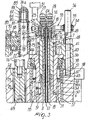
- the male mold half 1 comprises a plate 3 which is screwed into a sleeve 5 by means of a tubular shank 4; said sleeve 5 is in turn screwed into the lower end of a hollow tube 5a so as to form a single tubular stem 6 ( Figure 1).
- a pipe is inserted hermetically in the tubular shank 4 and defines a tubular interspace 8 together with the tubular stem 6 (i.e., with the sleeve 5 and the tube 5a).
- the sleeve 5 has, at its lower end, a portion 9 which tapers downward and is externally threaded; the plate 3 is centered hermetically in said portion and forms, together with the tubular shank 4, a chamber 10 which is connected to the interspace 8 through openings 11 of the tubular portion 4.
- the chamber 10, through openings 12 provided in the region of the shank 4 directly above the plate 3, is connected to the inside of the pipe 7.
- the portion 9 of the sleeve 5 and the plate 3 form the molding punch 13, which produces the worm of the thread C inside the cap A.
- the upper end of the pipe 7 is connected hermetically in a seat 16 of a cylindrical body which is in turn screwed hermetically, by means of a threaded portion thereof, in a seat 15 formed at the upper end of the hollow tube 5a.
- a narrow tube 17 lies coaxially inside the pipe 7, protrudes out of the top of the pipe 7 and is inserted hermetically in a hole 18 of the body 14.
- the lower end of the narrow tube 17 is inserted hermetically in a bush 20 ( Figure 3) which is in turn hermetically inserted in the bottom of the shank 4.
- the narrow tube 17, through the axial hole 21 of the bush 20, is connected to a plurality of holes 22 which are formed radially on the outside of the punch 13 through ports 23 constituted by openings provided in the centering region of the bell-shaped portion 9 between the edge of said portion and the plate 3.
- the upper end of the narrow tube 17 is connected, through a hole 24 arranged diametrically to the hole 18, to a supply of compressed air, which accordingly, after flowing through the narrow tube 17, can exit through the radial holes 22 and the openings 23.
- Two axial holes 25, 26 are formed in the body 14, eccentrically with respect to the hole 18, and are connected by means of couplings 27, 28 to the delivery and the return of a coolant fluid.
- the hole 26 is connected to the interspace 8, while the hole 25 is connected to the tubular channel 19 through a radial opening 29. This provides a connection between the couplings 27 and 28 which allows recirculation of the coolant fluid.
- the upper portion 30 of the sleeve 5, screwed onto the hollow tube 5a, has a smaller diameter than the remaining portion, so as to form an external annular shoulder 31.
- An axial slot 32 is formed in the portion 30 and is slidingly engaged by a key 33 which is rigidly coupled inside a tubular element 34 in which the stem 6 is slidingly guided with the portion 30 and the hollow tube 5a.
- the tubular element 34 is provided with a flange 35 which is centered in a cylindrical case 37 by means of a lower annular lip 36.
- the cylindrical case 37 is inserted in a cylindrical seat 38a of a rotating body which belongs to the structure of the carousel.
- Said body is constituted by a sort of rotating drum 38 which is mounted on a vertical shaft (not shown) whose axis is the rotation axis Z of the carousel.
- the case 37 rests on the drum 38 with a shoulder 39, so as to allow the mutual coaxial locking of the tubular element 34 and of the cylindrical case 37 by means of blocks 40 which are fastened onto the drum 38 by screws 41.
- a compartment 42 is formed between the case 37 and the tubular element 34 and accommodates a bush 43 which has an internal lip 44 at its lower end.
- a center bearing 45 is arranged at the top of the bush 43 and is guided between the wider portion of the case 37 and the tubular element 34.
- a ring 46 of elastic material is placed between the flange 35 and the center bearing 45, and a cylindrical spring 47 is interposed between the center bearing 45 and the lip 44 of the bush 43.
- the stem 6 can move between a raised position and a lowered position.
- the raised position is determined by the abutment of the shoulder 31 against the lower end of the tubular element 34 by means of the lifting action applied to the stem 6 by an additional cylindrical spring 48 which rests on the flange 35 in a downward region and on a ring 49 in an upward region, said ring abutting against circular segments 50 which are recessed in a perimetric slot of the body 14.
- the lowered position of the stem 6 is determined by a stationary cam 51 which, as will become apparent hereinafter from the description of the operation of the apparatus, acts on a free roller 52 which protrudes from a plate 53 which is applied to the body 14 which rests on the segments 50.
- the plate 53 is provided with an arm 54 which, by means of a bearing 55, can slide on a post 56 which rises vertically from the screw 41 on which it is screwed with the lower nut-shaped end 56a.
- a sleeve 57 is accommodated in the portion of the seat 38 arranged below the case 43, and its upper end is in contact with the lip 44 of the bush 43.
- the sleeve 57 is supported so that it can rotate and slide axially in the seat 38a by means of a bearing 58 and rotationally and axially supports the sleeve 5 by means of an additional bearing 59.
- the sleeve 57 comprises a portion 57a which protrudes below the drum 38a and ends with a collar 60 which is in sliding contact on the sleeve 5 and has, along its lower edge, teeth 61 for engagement on the edge of the cap A which is to be removed once molding has been completed.
- a bearing 63 is fixed above the collar 60 by means of a ring 62, and a ring gear 64 is formed above said bearing.
- the ring gear 64 meshes with a gear 65 which can rotate, by means of a bearing 66, on a pipe 67 which is inserted in a recess 68 of a rod 69 which passes through the drum 38.
- a bolt 69a is inserted in the pipe 67 and is screwed into the bottom of the recess 68, on which the pipe 67 is fixed by a nut 70.
- the rod 69 is mechanically connected to the sleeve 57 by a plate 71 which is fixed by the nut 70 against a collar 67a of the pipe 67 and has a seat in which the outer ring of the bearing 63 is fixed by means of a ring 72. Accordingly, the axial movement of the rod 69 actuates the simultaneous axial movement of the sleeve 57, while the ring gear 64 and the gear 65 remain mutually in mesh.
- the rod 69 can slide vertically, by means of a bearing 73, in a jacket 74 which is inserted in a seat 75 of the drum 38.
- the rod 69 protrudes upward with a shank 76, screwed into a threaded hole of the rod 69, and supports a cuff 78 arranged so as to be slideable on interposed bearings 77.
- the cuff 78 has a shoulder 79 and is surmounted by a plate 80 which is centered on the edge of the cuff 78 with a peripheral lip 81.
- a precompressed spring 82 rests on the plate 80, and its top rests on a collar 83 of a bush 84 which is guided on a threaded end portion 76a of the shank 76.
- the collar 83 is pushed by the precompressed spring 82 against a bolt 85 which is screwed into the threaded end portion 76a of the shank 76 so as to be able to adjust the precompression of the spring 82.
- a ring 86 is screwed onto the cuff 78 until it abuts against the shoulder 79, and a stem 87 protrudes from said ring and supports two rollers 88 and 89.
- the roller 89 is engaged in a cam 90 which is rigidly coupled to the fixed structure of the apparatus and is therefore stationary with respect to the drum 38.
- the roller 88 is guided in a vertical slot of a bracket (not shown in the drawing) which is fixed to the drum 38 and is designed to prevent the rotation of the shank 76 and of the rod 69.
- the cam 90 has a circular path which is concentric to the rotation axis Z of the carousel, so as to apply axial movements to the rod 69 and, by means of the connection provided by the plate 71, to the sleeve 57.
- the gear 65 meshes constantly with an idler gear 91 which is rotatably supported on a pivot 92 which protrudes downward from the drum 38a and is parallel to the rod 69.
- the gear 91 which as shown by the drawing is arranged on a rearward plane with respect to the plane of the gear 65, has longer teeth than the gear 65, so as to always remain in mesh with it even when the gear 65 moves away from the drum 38 in order to follow the movements of the rod 69.
- a third gear 93 meshes with the gear 91 and is keyed, together with two friction wheels 94, on a shaft 95 which is supported so that it can rotate below the drum 38.
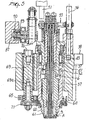
- Figure 3 illustrates only the upper part of the shaft 95 with the corresponding supporting bearing 96, which is accommodated in a seat of the drum 38.
- the friction wheels 94 are made of rubber-like material and are adapted to make contact with a track 97 which covers a certain angular portion outside the drum 38 and concentrically to the axis Z.
- the track 97 is fixed, by means of bolts 98 and nuts 99a, to fixed parts 100 of the apparatus, so as to produce a radial thrust on the friction wheels 94 which is sufficient to turn them and, with them, the sleeve 57 by means of the gear train 93, 91 and 65.
- a dose P (see Figure 1) of plastic material having a pasty consistency is deposited in the cavity of the female mold half 2.
- the female mold half 2 is lowered with respect to the punch 13, which by means of the spring 48 is actuated in the upward stop position determined by the abutment of the shoulder 31 of the stem 6 against the lower end of the tubular element 34.
- the stationary cam 90 which actuates the stroke of the rod 69 and therefore of the sleeve 57, is shaped so that in this step the threaded portion 9 of the punch 13 lies below the collar 60.
- the pressure applied to the female mold half 2 produces the gradual distribution of the plastic material in the molding chamber and the forming of the cap A (see Figure 2).
- the cam 90 actuates the descent of the rod 69, which by means of the plate 71 draws downward with it the sleeve 57.
- the collar 60 acts on the edge of the cap A which, by means of the thread, draws downward with it, with a stroke which is equal to the stroke of the rod 69, the stem 6 (see Figure 5), causing the compression of the spring 48.
- the friction wheels 94 engage the track 97 so as to start, by means of the gear train 93, 91, 65 and 64, the rotation of the sleeve 57 in the direction for unscrewing the cap A from the portion 9.
- the unscrewing of the cap is provided by the traction applied by the teeth 61 to the edge of the cap and by the simultaneous rise of the stem 6 caused by the return force applied by the spring 48 (see Figure 7).
- the cam 51 intervenes: by making contact with the roller 52, said cam prevents a sudden upward movement of the stem 6, allowing only its gradual rise as unscrewing of the cap advances (see Figure 6).
- valve means which intervene when the female mold half 2 has separated from the punch 13.
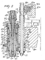
- Figure 8 shows the tubular stem 6*, which supports, at its lower end, the shaped punch 13* for forming cylindrical caps A*.
- the tubular stem 6* can slide in a tubular element 34* on which the sleeve 57* is guided.
- a bearing 58* By means of a bearing 58*, the sleeve 57* is guided in the provided seat of the drum 38*.
- a ring gear 64* can rotate by means of a bearing 101 on the lower portion of the sleeve 57*, and a collar 60* protrudes downward from said ring gear in sliding contact on the outer surface of the punch 13*.
- the collar 60* has, at the top, a circular plane 102 for contact with the lower edge of the sleeve 57* and, in a downward region, a plurality of teeth 61* for engagement on the edge of the cap A*.
- the ring gear 64* meshes with a gear 65* which is keyed on a tubular column 103 which is supported so that it can rotate and slide axially, by means of bearings 104 and 105, in a guiding seat 106 of the drum 38* which is parallel to the stem 6* and is radially internal thereto with respect to the rotation axis Z of the carousel.
- the tubular column 103 is driven through a plate 71* which connects it to the sleeve 57*.
- the plate 71* has an opening for the passage of the sleeve 57*; said opening is shaped so that its edge engages between two flanges 107, 108 of the sleeve 57* and produces a side-fit (axial and rotary) coupling with the sleeve 57*.
- the angular arrangement of the sleeve 57* with respect to the plate 71* is provided by means of a pin 109 which is guided in a radial hole 110 of the plate 71* and can move by acting on an external knob 111 in contrast with the action of a return spring 112.
- the plate 71* is rigidly coupled to the tubular column 103, at the portion that lies between the gear 65* and the lower face of the drum 38*, by means of two thrust bearings 113 and 114 which allow the rotation of the tubular column 103 and the transfer of thrusts onto the plate 71* and therefore onto the sleeve 57*.
- the upper end of the tubular column 103 lies above the drum 38*, and a pinion 115 is formed thereon; said pinion is connected, by means of a gear train generally designated by the reference numeral 116, to a source of motion.
- the pinion 115 has an axially extended set of teeth, so as to remain in mesh with the gears 116 during the axial movements of the tubular column 103.
- a cylindrical rod 120 (which corresponds to the parts 69, 76 of the version of Figures 1 to 4) is rotatably supported, by means of a lower bearing 117 and an upper bearing 118, in the tubular column 103, and rests on the column by means of a flange 119.
- the top of the rod 120 protrudes from the tubular column 103, and a stem 87* is radially fixed thereon and supports a follower roller 89* of an axial cam 90*.
- the cam 90* is rigidly coupled to the fixed structure of the apparatus and is therefore stationary with respect to the drum 38*, and its shape is circular and concentric with respect to the rotation axis Z of the carousel.
- a roller 88* is arranged on the stem 87*, on the outside of the cam 90*, and is guided in a vertical slot of a bracket (not shown in the drawing) which is rigidly coupled to the drum 38* and is meant to prevent the rotation of the rod 120.
- the cam 90* positively actuates the downward movements of the sleeve 57* only over an angle which is sufficient to remove the cap A* formed by the punch 13*; over the remaining rotation angle, the sleeve 57* can move upward in contrast with elastic abutment means.
- Said means are constituted by a ring of elastic rubber-like material 46* which is interposed between the flange 35* of the tubular element 34* and a center bearing 45* which rests on a bush 43* which is accommodated in the case 37*.
- the bush 43* has an internal lip 44* on which a cylindrical spring 47* rests, said spring being suitable to act against the center bearing 45*.
- the cam 90* actuates the descent of the rod 120 and starts the rotation of the tubular column 103 by means of the gear train 116, so that the collar 60* performs a descent and rotation which cause the unscrewing of the cap A* from the punch 13*.
- the axial thrust on the rod 120 actuated by the cam 90* and transmitted to the collar 60* by means of the plate 71* and the sleeve 57*, acts on the cap A*, which is actuated downward, drawing with it the punch 13* and the stem 6* and compressing the return spring 48*.
- a further embodiment of the present invention shown in Figures 9 and 10, has, instead of the track 97, a toothed sector 121 which lies concentrically to the axis Z and is such as to mesh directly with the gear 93 only at the rotation angle of the carousel in which unscrewing of the cap is provided.
- the gear 93 supports a free roller 122 which is eccentric with respect to the rotation axis of the gear 93 and which, at the beginning of the toothed sector 121, moves along an entry cam 123 which is shaped so as to turn the gear 93 so that its teeth can mesh with those of the toothed sector.
- a further cam 124 orientates the gear 93 in the angular position that allows the roller 122 to mate with the cam 123.
- the kinematic connection of the toothed sector 121 with the gear 93 can be achieved, instead of directly as above-described, by means of an auxiliary gear which is keyed on the shaft 95 above the gear 93.
Applications Claiming Priority (3)
| Application Number | Priority Date | Filing Date | Title |
|---|---|---|---|
| ITBO000256 | 2000-05-05 | ||
| IT2000BO000256A IT1321322B1 (it) | 2000-05-05 | 2000-05-05 | Apparecchiatura a giostra per la fabbricazione, mediante stampaggio apressione, di capsule in materiale plastico |
| PCT/EP2000/008389 WO2001085419A1 (en) | 2000-05-05 | 2000-08-28 | Carousel-type apparatus for manufacturing caps made of plastics by compression molding |
Publications (2)
| Publication Number | Publication Date |
|---|---|
| EP1278621A1 EP1278621A1 (en) | 2003-01-29 |
| EP1278621B1 true EP1278621B1 (en) | 2005-11-02 |
Family
ID=11438450
Family Applications (1)
| Application Number | Title | Priority Date | Filing Date |
|---|---|---|---|
| EP00958508A Expired - Lifetime EP1278621B1 (en) | 2000-05-05 | 2000-08-28 | Carousel-type apparatus for manufacturing caps made of plastics by compression molding |
Country Status (19)
| Country | Link |
|---|---|
| US (1) | US6585508B1 (it) |
| EP (1) | EP1278621B1 (it) |
| JP (1) | JP4762475B2 (it) |
| KR (1) | KR100602618B1 (it) |
| CN (1) | CN1219634C (it) |
| AT (1) | ATE308412T1 (it) |
| AU (1) | AU781431C (it) |
| BR (1) | BR0012160B1 (it) |
| CA (1) | CA2377882C (it) |
| DE (1) | DE60023755T2 (it) |
| ES (1) | ES2249294T3 (it) |
| HU (1) | HU225199B1 (it) |
| IT (1) | IT1321322B1 (it) |
| MX (1) | MXPA02000113A (it) |
| PL (1) | PL195356B1 (it) |
| RU (1) | RU2244625C2 (it) |
| TR (1) | TR200200144T1 (it) |
| TW (1) | TW568823B (it) |
| WO (1) | WO2001085419A1 (it) |
Families Citing this family (21)
| Publication number | Priority date | Publication date | Assignee | Title |
|---|---|---|---|---|
| US6602065B1 (en) | 2000-08-22 | 2003-08-05 | Owens-Illinois Closure Inc. | Apparatus for compression molding plastic closures |
| ITBO20000704A1 (it) * | 2000-12-04 | 2002-06-04 | Sacmi | Apparecchiatura a giostra per la fabbricazione mediante stampaggio a compressione, di articoli in materiale plastico |
| EP1243393A1 (de) * | 2001-03-19 | 2002-09-25 | Oberburg Engineering Ag | Verfahren zum Pressformen von thermoplastischem Kunststoff |
| ITRE20030005A1 (it) * | 2003-01-20 | 2004-07-21 | Sacmi | Metodo per la formatura di oggetti mediante stampaggio |
| US20040180107A1 (en) * | 2003-03-14 | 2004-09-16 | Zeno Zuffa | Mould for plastics items |
| ITMO20040144A1 (it) * | 2004-06-07 | 2004-09-07 | Sacmi | Apparati e metodo per formare oggetti |
| US7157037B2 (en) * | 2004-12-20 | 2007-01-02 | Creating Mold Solutions, Inc. | Apparatus for making threaded articles in a plastic injection molding process |
| ITMO20050224A1 (it) * | 2005-09-07 | 2007-03-08 | Sacmi | Stampi per lo stampaggio di oggetti in materia plastica e metodo per produrre un elemento di stampo |
| US7241129B2 (en) | 2005-10-31 | 2007-07-10 | Owens-Illinois Closure Inc. | Machine for compression molding closure shells |
| US7353725B2 (en) * | 2005-11-09 | 2008-04-08 | Caterpillar Inc. | Method of shifting gears in a work machine |
| JP4506734B2 (ja) * | 2006-03-31 | 2010-07-21 | Tdk株式会社 | 成形装置 |
| US7628601B2 (en) * | 2007-07-30 | 2009-12-08 | Rexam Closure Systems Inc. | Machine for compression molding plastic articles |
| CN101767407B (zh) * | 2008-12-27 | 2013-11-06 | 鸿富锦精密工业(深圳)有限公司 | 螺纹模具及其退牙结构 |
| IT1392824B1 (it) * | 2009-02-13 | 2012-03-23 | Sacmi | Apparato per formare oggetti |
| KR102381689B1 (ko) | 2015-01-30 | 2022-04-01 | 사크미 코오퍼레이티바 메카니치 이몰라 쏘시에타 코오퍼레이티바 | 압축 몰드 |
| ITUA20161670A1 (it) * | 2016-03-15 | 2017-09-15 | Sacmi | Stampo femmina. |
| IT201600076240A1 (it) * | 2016-07-20 | 2018-01-20 | Sacmi | Punzone per stampi a compressione |
| CN106393537B (zh) * | 2016-11-22 | 2019-01-15 | 华南理工大学 | 一种多模腔并行的橡塑制品批次压塑成型方法及装置 |
| CN112659398B (zh) * | 2021-01-12 | 2022-06-07 | 温州市隆昌塑料有限公司 | 全自动混合装置、塑料生产系统和生产方法 |
| CN112754045B (zh) * | 2021-02-02 | 2023-06-09 | 常宁市永青林业发展有限公司 | 一种基于压制成型的茶花籽饲料加工装置 |
| CN113458988B (zh) * | 2021-07-20 | 2023-06-23 | 安徽佑开科技有限公司 | 一种用于制作砂轮的模具填充装置 |
Family Cites Families (14)
| Publication number | Priority date | Publication date | Assignee | Title |
|---|---|---|---|---|
| US2155316A (en) * | 1936-08-18 | 1939-04-18 | Lauterbach Corp | Machine for molding plastic materials |
| US2218456A (en) | 1938-02-12 | 1940-10-15 | Owens Illinois Glass Co | Apparatus for molding plastic materials |
| JPS58173612A (ja) * | 1982-04-06 | 1983-10-12 | Japan Crown Cork Co Ltd | 回転式合成樹脂製容器蓋加圧成形装置 |
| FI64910C (fi) * | 1982-04-21 | 1984-02-10 | Lupoplast Oy | Anordning foer avlaegsning av kaernor ur presstycken med innergaenga |
| JPS60245517A (ja) * | 1984-05-22 | 1985-12-05 | Toyo Seikan Kaisha Ltd | 圧縮成形装置 |
| ES8603597A1 (es) | 1984-12-14 | 1985-11-16 | Platt Saco Lowell Sa | Perfeccionamientos en el control de las fibras en los sistemas de estirajede bolsas en las maquinas en el proceso de hilatura |
| JPS62264923A (ja) | 1986-05-14 | 1987-11-17 | Sumitomo Heavy Ind Ltd | 内ねじ付射出成形品の離型方法 |
| JPH0624746B2 (ja) * | 1990-09-04 | 1994-04-06 | 株式会社型システム | ねじ付製品用金型 |
| US5421717A (en) * | 1994-05-31 | 1995-06-06 | Husky Injection Molding Systems Ltd. | Apparatus for forming threaded molded articles |
| US5383780A (en) * | 1993-09-27 | 1995-01-24 | Husky Injection Molding Systems Ltd. | Apparatus for forming threaded molded article |
| US5554327A (en) | 1993-10-14 | 1996-09-10 | Owens-Illinois Closure Inc. | Method and apparatus for compression molding plastic articles |
| US5451360A (en) | 1993-10-14 | 1995-09-19 | Owens-Illinois Closure Inc. | Method and apparatus for compression molding closure liners |
| IT1274905B (it) * | 1994-09-19 | 1997-07-25 | Sacmi | Apparecchiatura per la fabbricazione di articoli di materiale plasticoin particolare tappi a vite, mediante stampaggio a pressione. |
| US6238202B1 (en) * | 1999-02-26 | 2001-05-29 | Unique Mould Makers Limited | Apparatus for ejecting threaded injection molded parts |
-
2000
- 2000-05-05 IT IT2000BO000256A patent/IT1321322B1/it active
- 2000-08-28 WO PCT/EP2000/008389 patent/WO2001085419A1/en active IP Right Grant
- 2000-08-28 CA CA002377882A patent/CA2377882C/en not_active Expired - Fee Related
- 2000-08-28 RU RU2002102875/12A patent/RU2244625C2/ru not_active IP Right Cessation
- 2000-08-28 HU HU0203037A patent/HU225199B1/hu not_active IP Right Cessation
- 2000-08-28 DE DE60023755T patent/DE60023755T2/de not_active Expired - Lifetime
- 2000-08-28 US US09/649,024 patent/US6585508B1/en not_active Expired - Lifetime
- 2000-08-28 CN CNB008099073A patent/CN1219634C/zh not_active Expired - Lifetime
- 2000-08-28 TR TR2002/00144T patent/TR200200144T1/xx unknown
- 2000-08-28 BR BRPI0012160-6A patent/BR0012160B1/pt not_active IP Right Cessation
- 2000-08-28 AT AT00958508T patent/ATE308412T1/de active
- 2000-08-28 EP EP00958508A patent/EP1278621B1/en not_active Expired - Lifetime
- 2000-08-28 JP JP2001582054A patent/JP4762475B2/ja not_active Expired - Lifetime
- 2000-08-28 ES ES00958508T patent/ES2249294T3/es not_active Expired - Lifetime
- 2000-08-28 KR KR1020027000083A patent/KR100602618B1/ko not_active IP Right Cessation
- 2000-08-28 MX MXPA02000113A patent/MXPA02000113A/es active IP Right Grant
- 2000-08-28 AU AU70003/00A patent/AU781431C/en not_active Ceased
- 2000-08-28 PL PL00351718A patent/PL195356B1/pl unknown
-
2001
- 2001-06-28 TW TW090115682A patent/TW568823B/zh not_active IP Right Cessation
Also Published As
| Publication number | Publication date |
|---|---|
| AU7000300A (en) | 2001-11-20 |
| HU225199B1 (en) | 2006-08-28 |
| PL351718A1 (en) | 2003-06-02 |
| US6585508B1 (en) | 2003-07-01 |
| BR0012160A (pt) | 2002-03-19 |
| PL195356B1 (pl) | 2007-09-28 |
| BR0012160B1 (pt) | 2010-08-24 |
| CN1359324A (zh) | 2002-07-17 |
| CA2377882A1 (en) | 2001-11-15 |
| AU781431B2 (en) | 2005-05-26 |
| ITBO20000256A1 (it) | 2001-11-05 |
| DE60023755D1 (de) | 2005-12-08 |
| KR20020024299A (ko) | 2002-03-29 |
| JP2003532557A (ja) | 2003-11-05 |
| JP4762475B2 (ja) | 2011-08-31 |
| WO2001085419A1 (en) | 2001-11-15 |
| EP1278621A1 (en) | 2003-01-29 |
| AU781431C (en) | 2006-08-17 |
| TR200200144T1 (tr) | 2002-11-21 |
| DE60023755T2 (de) | 2006-06-01 |
| KR100602618B1 (ko) | 2006-07-20 |
| ATE308412T1 (de) | 2005-11-15 |
| MXPA02000113A (es) | 2002-07-02 |
| IT1321322B1 (it) | 2004-01-08 |
| CA2377882C (en) | 2008-10-07 |
| ES2249294T3 (es) | 2006-04-01 |
| CN1219634C (zh) | 2005-09-21 |
| TW568823B (en) | 2004-01-01 |
| HUP0203037A2 (en) | 2003-04-28 |
| RU2244625C2 (ru) | 2005-01-20 |
Similar Documents
| Publication | Publication Date | Title |
|---|---|---|
| EP1278621B1 (en) | Carousel-type apparatus for manufacturing caps made of plastics by compression molding | |
| EP1140454B1 (en) | Device for manufacturing plastic items, particularly caps for closing containers | |
| KR100364522B1 (ko) | 압력몰딩에의해플라스틱제품,특히스크루밀폐기를제작하기위한장치 | |
| US7331777B2 (en) | Compression molding machine | |
| CN101579905B (zh) | 一种旋转脱模塑料瓶盖模压机 | |
| RU2002102875A (ru) | Устройство карусельного типа для изготовления крышек из пластмассы прямым формованием | |
| CA2444848C (en) | Carousel apparatus for manufacturing articles made of plastics by compression molding | |
| US6767201B2 (en) | Carrousel apparatus for manufacturing, by compression molding, plastics items | |
| CN1195615C (zh) | 制造塑料件用的模子 | |
| AU2006309262C1 (en) | Method and machine for compression molding closure shells | |
| CN116210929A (zh) | 一种海参肽成品提取物压片装置及其压片方法 | |
| AU2002251071A1 (en) | Ejecting compression molded caps | |
| MX2008005559A (en) | Method and machine for compression molding closure shells |
Legal Events
| Date | Code | Title | Description |
|---|---|---|---|
| PUAI | Public reference made under article 153(3) epc to a published international application that has entered the european phase |
Free format text: ORIGINAL CODE: 0009012 |
|
| 17P | Request for examination filed |
Effective date: 20020118 |
|
| AK | Designated contracting states |
Designated state(s): AT BE CH CY DE DK ES FI FR GB GR IE IT LI LU MC NL PT SE |
|
| AX | Request for extension of the european patent |
Extension state: AL LT LV MK RO SI |
|
| GRAP | Despatch of communication of intention to grant a patent |
Free format text: ORIGINAL CODE: EPIDOSNIGR1 |
|
| GRAS | Grant fee paid |
Free format text: ORIGINAL CODE: EPIDOSNIGR3 |
|
| 17Q | First examination report despatched |
Effective date: 20041223 |
|
| GRAA | (expected) grant |
Free format text: ORIGINAL CODE: 0009210 |
|
| RAP1 | Party data changed (applicant data changed or rights of an application transferred) |
Owner name: SACMI COOPERATIVA MECCANICI IMOLA SOCIETA'COOPERAT |
|
| AK | Designated contracting states |
Kind code of ref document: B1 Designated state(s): AT BE CH CY DE DK ES FI FR GB GR IE IT LI LU MC NL PT SE |
|
| PG25 | Lapsed in a contracting state [announced via postgrant information from national office to epo] |
Ref country code: FI Free format text: LAPSE BECAUSE OF FAILURE TO SUBMIT A TRANSLATION OF THE DESCRIPTION OR TO PAY THE FEE WITHIN THE PRESCRIBED TIME-LIMIT Effective date: 20051102 |
|
| REG | Reference to a national code |
Ref country code: GB Ref legal event code: FG4D |
|
| REG | Reference to a national code |
Ref country code: CH Ref legal event code: NV Representative=s name: ROTTMANN, ZIMMERMANN + PARTNER AG Ref country code: CH Ref legal event code: EP |
|
| REF | Corresponds to: |
Ref document number: 60023755 Country of ref document: DE Date of ref document: 20051208 Kind code of ref document: P |
|
| PG25 | Lapsed in a contracting state [announced via postgrant information from national office to epo] |
Ref country code: GR Free format text: LAPSE BECAUSE OF FAILURE TO SUBMIT A TRANSLATION OF THE DESCRIPTION OR TO PAY THE FEE WITHIN THE PRESCRIBED TIME-LIMIT Effective date: 20060202 Ref country code: SE Free format text: LAPSE BECAUSE OF FAILURE TO SUBMIT A TRANSLATION OF THE DESCRIPTION OR TO PAY THE FEE WITHIN THE PRESCRIBED TIME-LIMIT Effective date: 20060202 Ref country code: DK Free format text: LAPSE BECAUSE OF FAILURE TO SUBMIT A TRANSLATION OF THE DESCRIPTION OR TO PAY THE FEE WITHIN THE PRESCRIBED TIME-LIMIT Effective date: 20060202 |
|
| REG | Reference to a national code |
Ref country code: ES Ref legal event code: FG2A Ref document number: 2249294 Country of ref document: ES Kind code of ref document: T3 |
|
| PG25 | Lapsed in a contracting state [announced via postgrant information from national office to epo] |
Ref country code: PT Free format text: LAPSE BECAUSE OF FAILURE TO SUBMIT A TRANSLATION OF THE DESCRIPTION OR TO PAY THE FEE WITHIN THE PRESCRIBED TIME-LIMIT Effective date: 20060403 |
|
| ET | Fr: translation filed | ||
| PG25 | Lapsed in a contracting state [announced via postgrant information from national office to epo] |
Ref country code: IE Free format text: LAPSE BECAUSE OF NON-PAYMENT OF DUE FEES Effective date: 20060828 |
|
| PG25 | Lapsed in a contracting state [announced via postgrant information from national office to epo] |
Ref country code: MC Free format text: LAPSE BECAUSE OF NON-PAYMENT OF DUE FEES Effective date: 20060831 |
|
| PLBE | No opposition filed within time limit |
Free format text: ORIGINAL CODE: 0009261 |
|
| STAA | Information on the status of an ep patent application or granted ep patent |
Free format text: STATUS: NO OPPOSITION FILED WITHIN TIME LIMIT |
|
| 26N | No opposition filed |
Effective date: 20060803 |
|
| REG | Reference to a national code |
Ref country code: IE Ref legal event code: MM4A |
|
| PG25 | Lapsed in a contracting state [announced via postgrant information from national office to epo] |
Ref country code: CY Free format text: LAPSE BECAUSE OF FAILURE TO SUBMIT A TRANSLATION OF THE DESCRIPTION OR TO PAY THE FEE WITHIN THE PRESCRIBED TIME-LIMIT Effective date: 20051102 |
|
| PGFP | Annual fee paid to national office [announced via postgrant information from national office to epo] |
Ref country code: NL Payment date: 20100723 Year of fee payment: 11 |
|
| PGFP | Annual fee paid to national office [announced via postgrant information from national office to epo] |
Ref country code: LU Payment date: 20100727 Year of fee payment: 11 Ref country code: FR Payment date: 20100910 Year of fee payment: 11 Ref country code: AT Payment date: 20100722 Year of fee payment: 11 |
|
| PGFP | Annual fee paid to national office [announced via postgrant information from national office to epo] |
Ref country code: GB Payment date: 20100727 Year of fee payment: 11 |
|
| PGFP | Annual fee paid to national office [announced via postgrant information from national office to epo] |
Ref country code: BE Payment date: 20100729 Year of fee payment: 11 |
|
| REG | Reference to a national code |
Ref country code: CH Ref legal event code: PFA Owner name: SACMI COOPERATIVA MECCANICI IMOLA SOCIETA' COOPER Free format text: SACMI COOPERATIVA MECCANICI IMOLA SOCIETA' COOPERATIVA IN BREVE SACMI IMOLA S.C.#VIA PROVINCIALE SELICE 17/A#40026 IMOLA (IT) -TRANSFER TO- SACMI COOPERATIVA MECCANICI IMOLA SOCIETA' COOPERATIVA IN BREVE SACMI IMOLA S.C.#VIA PROVINCIALE SELICE 17/A#40026 IMOLA (IT) |
|
| BERE | Be: lapsed |
Owner name: *SACMI COOPERATIVA MECCANICI IMOLA SOCIETA' COOPER Effective date: 20110831 |
|
| REG | Reference to a national code |
Ref country code: NL Ref legal event code: V1 Effective date: 20120301 |
|
| GBPC | Gb: european patent ceased through non-payment of renewal fee |
Effective date: 20110828 |
|
| REG | Reference to a national code |
Ref country code: FR Ref legal event code: ST Effective date: 20120430 |
|
| PG25 | Lapsed in a contracting state [announced via postgrant information from national office to epo] |
Ref country code: NL Free format text: LAPSE BECAUSE OF NON-PAYMENT OF DUE FEES Effective date: 20120301 Ref country code: BE Free format text: LAPSE BECAUSE OF NON-PAYMENT OF DUE FEES Effective date: 20110831 |
|
| PG25 | Lapsed in a contracting state [announced via postgrant information from national office to epo] |
Ref country code: FR Free format text: LAPSE BECAUSE OF NON-PAYMENT OF DUE FEES Effective date: 20110831 Ref country code: GB Free format text: LAPSE BECAUSE OF NON-PAYMENT OF DUE FEES Effective date: 20110828 |
|
| REG | Reference to a national code |
Ref country code: AT Ref legal event code: MM01 Ref document number: 308412 Country of ref document: AT Kind code of ref document: T Effective date: 20110828 |
|
| PG25 | Lapsed in a contracting state [announced via postgrant information from national office to epo] |
Ref country code: AT Free format text: LAPSE BECAUSE OF NON-PAYMENT OF DUE FEES Effective date: 20110828 |
|
| PG25 | Lapsed in a contracting state [announced via postgrant information from national office to epo] |
Ref country code: LU Free format text: LAPSE BECAUSE OF NON-PAYMENT OF DUE FEES Effective date: 20110828 |
|
| PGFP | Annual fee paid to national office [announced via postgrant information from national office to epo] |
Ref country code: ES Payment date: 20150812 Year of fee payment: 16 |
|
| REG | Reference to a national code |
Ref country code: CH Ref legal event code: PCAR Free format text: NEW ADDRESS: GARTENSTRASSE 28 A, 5400 BADEN (CH) |
|
| PG25 | Lapsed in a contracting state [announced via postgrant information from national office to epo] |
Ref country code: ES Free format text: LAPSE BECAUSE OF NON-PAYMENT OF DUE FEES Effective date: 20160829 |
|
| REG | Reference to a national code |
Ref country code: ES Ref legal event code: FD2A Effective date: 20181122 |
|
| PGFP | Annual fee paid to national office [announced via postgrant information from national office to epo] |
Ref country code: DE Payment date: 20190722 Year of fee payment: 20 Ref country code: IT Payment date: 20190722 Year of fee payment: 20 |
|
| PGFP | Annual fee paid to national office [announced via postgrant information from national office to epo] |
Ref country code: CH Payment date: 20190722 Year of fee payment: 20 |
|
| REG | Reference to a national code |
Ref country code: DE Ref legal event code: R071 Ref document number: 60023755 Country of ref document: DE |
|
| REG | Reference to a national code |
Ref country code: CH Ref legal event code: PL |