EP1277493A2 - Medizinisches Einweggerät - Google Patents
Medizinisches Einweggerät Download PDFInfo
- Publication number
- EP1277493A2 EP1277493A2 EP02090258A EP02090258A EP1277493A2 EP 1277493 A2 EP1277493 A2 EP 1277493A2 EP 02090258 A EP02090258 A EP 02090258A EP 02090258 A EP02090258 A EP 02090258A EP 1277493 A2 EP1277493 A2 EP 1277493A2
- Authority
- EP
- European Patent Office
- Prior art keywords
- unit
- therapy device
- lock
- electrical therapy
- reuse
- Prior art date
- Legal status (The legal status is an assumption and is not a legal conclusion. Google has not performed a legal analysis and makes no representation as to the accuracy of the status listed.)
- Granted
Links
Images


Classifications
-
- A—HUMAN NECESSITIES
- A61—MEDICAL OR VETERINARY SCIENCE; HYGIENE
- A61N—ELECTROTHERAPY; MAGNETOTHERAPY; RADIATION THERAPY; ULTRASOUND THERAPY
- A61N1/00—Electrotherapy; Circuits therefor
- A61N1/18—Applying electric currents by contact electrodes
- A61N1/32—Applying electric currents by contact electrodes alternating or intermittent currents
- A61N1/36—Applying electric currents by contact electrodes alternating or intermittent currents for stimulation
- A61N1/372—Arrangements in connection with the implantation of stimulators
Definitions
- the invention is based on the idea of an electrical therapy device to provide which a lock-release unit and Has reuse lock unit, wherein the reuse lock unit the functions of the electrical therapy device during an implantation depending on the state of the lock release unit in derogation.
- the lock release unit is either at an implantation or an explantation of the electrical therapy device triggered.
- the reuse lockout unit when implanted into one Body queries the state of the lock release unit and based on this Condition can determine whether the electrical therapy device already has been implanted before. If the state of the lock release unit indicates that the electrical therapy device the reuse lockout unit interrupts the functions of the electrical therapy device. With others Words, the electrical therapy device cannot be a second Implant times and thus reuse. The state of the lock trip unit becomes like this during an implantation or an explantation changed to allow the reuse lockout unit to recognize that the electrical therapy device has already been used in advance has been.
- a heart pacemaker for example, also falls under the mentioned embodiment variant, in which a component is connected to an electrode line is destroyed or changed, the pacemaker then only remains functional with the electrode lead connected.
- the reuse lock is in this case with connection of the electrode cable Initialized. With subsequent disconnection of the electrode lead from Pacemaker then triggers the reuse lock and the function of the pacemaker or defibrillator is permanently prevented. This can happen because of the change or destruction of the corresponding component with connection of the electrode line subsequent disconnection of the electrode line the further change the destruction of a component of the implant.
- making the electrical unusable Therapy device thus initially initializing the Reuse lock ahead and later trigger the reuse lock.
- the reuse block must therefore first be armed before it can be triggered. It will be both the initialization of the electrical therapy device during implantation as well as triggering the reuse lock or the triggered reuse lock captured so the functions of the electrical therapy device can be prevented. In other words the functions of the electrical therapy device are prevented during or during the implantation of the electrical therapy device.
- the state of the lock release unit explanting the electrical therapy device is set so that the reuse lock unit is detected can that the electrical therapy device is explanted is.
- the reuse lock unit can perform the functions of the electrical Stop the therapy device immediately as soon as it is due to the State of the blocking trigger unit has detected that the therapy device is no longer in the body, d. H. an explantation takes place is.
- the functions of the electrical Therapy devices interrupted immediately after detection of the explant be while interrupting the functions of the electrical Therapy device in the variant set out in claim 1 with a new implantation of the electrical therapy device in a body takes place.
- the above-mentioned embodiment variant for example also a pacemaker with commissioning, after connecting a Electrode lead, irrevocably put in a state that the The pacemaker is unusable after first disconnecting the Leads directly from the pacemaker.
- the electrical therapy device also a power supply unit, which the therapy device supplied with the necessary energy.
- the reuse lockout unit has a trigger that is suitable for this is the power supply unit, depending on the state of the Lock-release unit, from the remaining units of the electrical therapy device to disconnect in order to supply the energy to the therapy device to interrupt.
- the electrical therapy device a control means on which the general functions controls the therapy device.
- the reuse lockout unit is suitable for the electrical control of the therapy device by instructions to the control means during an implantation of the electrical therapy device depending on the state of the To block or prevent the blocking trigger unit at least partially. The status of the lock release unit is therefore queried. Shows this a restart, the function of the control means of the implant is prevented. This makes an electrical or electronic Locking the electrical therapy device allows so that This cannot be used anymore, because it has already been used in one Body has been implanted.
- the lock release unit can be designed so that its state with one query is changed so that a second query is in a second state, which indicates that the lock release unit was previously queried and therefore an undesirable Reuse is attempted.
- the states of the lock release unit can be represented, for example, by a single bit in a memory be that in the sense of a flag when the memory is first addressed is set and then either not at all or only under special conditions can be reset.
- a suitable one Memory would be an EPROM, for example.
- the reuse lockout unit a first receiving unit.
- This first receiving unit provides either a telemetric receiving unit or a magnetically activatable receiving unit.
- a telemetric The receiving unit is suitable for receiving a telemetric Lock signal to activate or trigger the lock release unit.
- a magnetically activatable receiver unit is suitable for to activate the blocking release unit when it is magnetically activated or trigger.
- the lock release unit can be located from outside the body non-contact - telemetric or magnetic - to be activated to avoid returning the therapy device after an explant is implanted in a body.
- the blocking trigger unit can, for example, in the course of a first implantation be performed.
- control means has one Memory for a patient-specific factory exit program for Operating the electrical therapy devices.
- the reuse lockout unit also has an initialization detection unit which is designed to lock the trigger unit when the Factory output program stored in the memory of the control means to activate or trigger.
- the reuse lock unit has an impedance measuring unit, which measures the impedance an electrode line connected to the electrical therapy devices determined and the lock release unit triggers or activated when the measured impedance of the electrode line from a given one Value or range of values deviates.
- the reuse lock unit can determine when the electrode lead from the electrical therapy device Will get removed. Based on this finding, the lock release unit activated and the electrical therapy device is immediately or at the latest locked on a subsequent implantation so they don't more can be used.
- the electrical therapy device a locking deactivating means, which is designed for this purpose is the state of the lock release unit upon receipt of a lock disable signal to overwrite.
- the state of the lock release unit can be changed so that a authorized reuse or reprocessing is possible.
- the blocking deactivating means a telemetric receiving unit, which is designed for this purpose the lock deactivation signal is to be received telemetrically. Consequently enables the reuse lock of the electrical therapy device is deactivated without contact.
- the blocking deactivating means a decoding means which is suitable for encoding a Decode password from a received signal.
- the Locking-deactivating means furthermore has a verifying means, which it does is configured to verify the receiving decoded password and reset the state of the lock trigger unit when the receiving Password is correct.
- the reuse lock unit has a detection unit which is suitable for Monitor the heart's ECG signals and lock the triggering unit too activate as soon as there are no more ECG signals in a specified time interval be received. It can thus be detected that the electrical Therapy device is no longer in a body and thus must be blocked.
- the electrical therapy device a temperature sensor that measures the temperature in the electrical therapy device detected and to the reuse lock unit passes.
- the reuse lockout unit also has a temperature evaluation unit, which is suitable for the lock release unit to activate when the output from the temperature sensor Temperature in the electrical therapy device below one predetermined threshold falls. Thus it can be determined based on the temperature whether the electrical therapy device is still in the body. If not, the temperature in the electrical Therapy device fall below a predetermined value, so that the lock release unit is activated.
- the invention is based on the idea of an electrical therapy device to be provided along with the associated packaging.
- the packaging has a magnet, which is arranged in this way in the packaging is that a magnetically activated receiving unit in the reuse lock unit when removing the electrical therapy device magnetically activated from the packaging and thus the Lock release unit is triggered. When removing the electrical therapy device the packaging becomes the reuse lock activated.
- the invention is also based on a medical implant with a Housing and the features of claim 17 solved.
- the invention is based on the idea of housing a medical device Implant at least in sections with a bio-compatible Provide layer, which chemically in contact with human tissue responding. The result of this chemical reaction is visible. The visible result can be used to determine whether this medical implant has already been implanted in a body is so that it cannot be used again.
- the ingredient can also be a chemical that results from contact irreversible with a patient's body chemistry after implantation recognizable from the outside, for example changed in color.
- a part of a purely mechanical implant such as a catheter may be provided. He can only partially be provided, in particular such that discoloration of the component a lettering like "This catheter has already been used and is not suitable for reuse ".
- Disposable locking connections can be used for connecting an electrode line to a pacemaker either on the pacemaker side or barbs on the electrode side that provide the connection preferably irretrievably destroyed on the part of the pacemaker, by mechanically destroying the pacemaker connection or non-removable remains of a required connector between Electrode lead and pacemaker in the pacemaker-side connector remain so that there is no more electrode lead to the pacemaker can be connected.
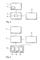
- FIG. 1 is a block diagram of an electrical therapy device shown according to a first embodiment.
- the electrical therapy device has a control means 1, a lock release unit 9, a Reuse lock unit 2 and a power supply unit 20 on.
- the reuse lock unit 2 is each with the control means 1, the lock release unit 9 and the power supply unit 20 connected.
- the reuse lock unit 2 has a trigger 3 and a first receiving unit 5.
- the trigger 3 is with the control means 1, the power supply unit 20 and the lock release unit 9 connected.
- the first receiving unit 5 is with the lock release unit 9 connected.
- the first receiving unit 5 is a wirelessly activatable receiving unit, such as a telemetric receiving unit or a magnetic one activatable receiver unit.
- the first receiving unit 5 can be for example by a telemetric signal (in the case of a telemetric Receiving unit) or by a magnet (for a magnetically activated Activate receiver unit). If the first receiving unit 5 receives a corresponding telemetric or magnetic signal, it activates the lock release unit 9.
- the trigger 3 is located between the control means 1 and the power supply unit 20 and can used to power supply unit 20 from the rest separate the electrical therapy device.
- the reuse lock unit 2 checks the condition the lock release unit 9. When the lock release unit 9 to this When activated, this is passed on to trigger 3, which then activated, and the connection between the power supply unit 20 and the control means 1 is interrupted. The control unit 1 is therefore no longer supplied with energy and is therefore switched off. The electrical therapy device can therefore no longer be used.
- FIG. 2 is a block diagram of an electrical therapy device shown according to the second embodiment.
- the therapy device has a control means 1, a reuse lock unit 2 and a lock release unit 9.
- the electrical therapy device has furthermore a connection 16 for an electrode line.
- the reuse lockout unit 2 is in each case with the control means 1, the lock release unit 9 and the connection 16 and has an impedance measuring unit 14 on.
- the impedance measuring unit 14 is with the Connection 16 for the electrode line and with the blocking release unit 9 connected.
- the impedance measuring unit 14 detects the impedance at the connection 16 and thus the impedance of a connected electrode line. This Acquisition can take place continuously or in discrete time intervals. In of the impedance measuring unit 14 include the measured impedance values a previously entered threshold value or threshold value range. If the measured impedance values go from this threshold range deviate, the impedance measuring unit 14 activates the blocking tripping unit 9.
- the previously entered threshold values or threshold value ranges are chosen such that a deviation from these Values can only be made when the electrode lead is out of the connector 16 is removed, i. H. when the electrode lead is disconnected.
- the reuse lock unit 2 checks the condition the lock release unit 9. When the lock release unit 9 to this When the time is activated, the reuse lock unit 2 issues an instruction to the control means 1 to control the functions of the electrical Block therapy device. Alternatively, the energy supply of the control means 1 as in the first embodiment Fig. 1 described, locked. In both cases, that the electrical therapy device can no longer be used can.
- FIG. 3 is a block diagram of an electrical therapy device shown according to a third embodiment.
- the electrical therapy device has a control means 1, a reuse lock unit 2 and a lock release unit 9.
- the reuse lockout unit 2 is in each case with the control means 1 and Lock-release unit 9 connected.
- the control means 1 has a memory 7 to save a factory exit program.
- the reuse lockout unit 2 has an initialization detection unit 6, which is connected to that of the lock release unit 9 and the memory 7 is.
- the initialization detection unit 6 detects an initialization of the Factory output program in the memory 7 for controlling the electrical Therapy device according to the patient-specific parameters during an implantation of the electrical therapy device in a Body. If such initialization of the factory exit program has been detected, the initialization detection unit 6 activates the lock release unit 9th
- FIG. 4 shows a block diagram of an electrical therapy device according to the fourth embodiment of the invention.
- the electrical Therapy device has a control means 1, a reuse lock unit 2, a lock release unit 9 and a lock deactivation means 10 on.
- the reuse lock unit 2 is each with the control means 1, the lock release unit 9 and the lock deactivation means 10 connected.
- the lock deactivation means 10 has one second receiving unit 11, a decoding unit 12 and a verification unit 13, which are arranged one after the other in this order.
- the second receiving unit 11 is, for example, a telemetric receiving unit as already described in the first embodiment has been.
- the second receiving unit 11 receives a telemetric signal through that data and instructions are transmitted.
- the receiving telemetric Signal is decoded in the decoding unit 12, so that the in data, instructions and information contained in the telemetric signal be extracted.
- the verification unit 13 checks these decoded Information with a given password. If the decoded Information or data corresponds to this specified password, the verification unit 13 deactivates the lock release unit 9, i. H. the state the lock release unit 9 is reset. By using it of a password and the verification of this password in the Verification unit 13 ensures that the reuse lock reset in the lock release unit 9 only by authorized persons can be. By removing the reuse block can be achieved in the blocking trigger unit 9 that the electrical Therapy device is not deactivated during an implantation, though this implantation may already be the second implantation represents.
- FIG. 5 is a block diagram of an electrical therapy device shown according to the fifth embodiment of the invention.
- the electrical Therapy device has a control means 1, a reuse lock unit 2 and a lock release unit 9 and a connection 16 for connecting an electrode line.
- the reuse lockout unit 2 is in each case with the control means 1, the connection 16 and the lock-release unit 9 connected and has a detection unit 21 on.
- the detection unit 21 is connected to the connection 16 and Lock-release unit 9 connected.
- the ECG signals of a patient's heart Via an electrode line connected to the connection 16 the ECG signals of a patient's heart to the detection unit 21 forwarded. There the EKG signals are continuous or at predetermined ones Points in time. As soon as no ECG signals in a given Time interval are received, the detection unit 21 is activated the lock release unit 9, d. H. the reuse lock is set. The absence of ECG signals is used as an indicator that the electrode lead from the electrical therapy device has been disconnected, therefore the electrical therapy device is not more in the patient's body, and an explantation of the therapy device is done.
- the reuse lock unit 2 can, on the one hand, immediately after the Activation of the lock release unit 9 or only after a subsequent one
- the implantation block the functions of the electrical therapy device or interrupt. More details are already there described above in relation to the first and second exemplary embodiments.
- FIG. 6 shows a block diagram of an electrical therapy device according to a sixth embodiment.
- the electrical therapy device has a control means 1, a reuse lock unit 2, a lock release unit 9 and a temperature sensor 23 on.
- the reuse lock unit 2 is each with the control means 1, the lock trigger unit 9 and the temperature sensor 23 connected and has a temperature evaluation unit 25.
- the temperature evaluation unit 25 is with the temperature sensor 23 and the lock-release unit 9 connected.
- the temperature sensor 23 detects the temperature in the electrical therapy device. This can be done continuously or at fixed intervals respectively.
- the temperature sensor 23 transmits the detected temperature to the temperature evaluation unit 25, where the detected temperature is compared with a predetermined threshold. If the captured If the temperature falls below the specified threshold, the temperature evaluation unit is activated 25 the lock release unit 9, d. H. the reuse lock is activated.
- the temperature in the electrical therapy device is used as an indicator of whether the electrical Therapy device is still in a body or whether one Explantation of the electrical therapy device has taken place.
- the reuse lock unit 2 can, on the one hand, immediately after the Activation of the lock release unit 9 or only after a subsequent one
- the implantation block the functions of the electrical therapy device or interrupt. Further details are already given above described in relation to the first and second embodiments.
- the memory 7 in the control means 1 can be a memory, for example have, in which patient-specific parameters are stored.
- This Memory could represent an EPROM, for example. H. the in this Stored parameters can no longer be added later to be changed. This would mean that the electrical therapy device only for a single medical indication for a special one Patient can be used.
- the lock-release unit 9 could, for example, by an electronic Switches, such as a transistor, a fuse, or a relay will be realized.
- Both for the lock release unit 9 and for the trigger 3 is preferred uses a fuse that burns out for activation is, so that the lock release unit and the trigger 3 after their activation can no longer be activated. This would ensure that the electrical therapy device is not reused without authorization or processed.
- pacemakers Defibrillators or the like understood.
- connection is 16 designed for an electrode line such that a section of the connection 16 broken when inserting the plug of the electrode line becomes.
- the plug of the electrode line provides a bridging of the broken section of the Connection 16 represents, so that an electrical connection still exists is.
- the plug of the electrode line is pulled, then the bridging of the breached section is removed and it is thus there is no longer an electrical connection.
- the lack of one electrical contact or the connection in the connection 16 after the plug of the electrode cable can be pulled used to power the electrical therapy device is interrupted and the electrical therapy device is not is more functional.
- a medical implant provided with a housing. It will Housing of the medical implant at least in sections with a coated bio-compatible layer. This bio-compatible layer is included designed to be in contact with human tissue chemically reacted. The result of this chemical reaction is there visible to the human eye.
- Another alternative embodiment of the invention shows a packaging for an electrical therapy device, for example according to the first embodiment.
- a magnet is so in or on the Packaging attached that the first magnetic activatable receiving unit 5 is activated when the electrical therapy device is off is removed from the packaging.
- an activation of the first receiving unit 5 causes the lock release unit 9 and thus the reuse lock activated becomes.
Landscapes
- Health & Medical Sciences (AREA)
- Animal Behavior & Ethology (AREA)
- Biomedical Technology (AREA)
- Nuclear Medicine, Radiotherapy & Molecular Imaging (AREA)
- Radiology & Medical Imaging (AREA)
- Life Sciences & Earth Sciences (AREA)
- Engineering & Computer Science (AREA)
- General Health & Medical Sciences (AREA)
- Public Health (AREA)
- Veterinary Medicine (AREA)
- Electrotherapy Devices (AREA)
- Magnetic Treatment Devices (AREA)
- External Artificial Organs (AREA)
Abstract
Description
- Figur 1
- ein Blockschaltbild einer elektrischen Therapievorrichtung gemäß einem ersten Ausführungsbeispiel der Erfindung,
- Figur 2
- ein Blockschaltbild einer elektrischen Therapievorrichtung gemäß einem zweiten Ausführungsbeispiel der Erfindung,
- Figur 3
- ein Blockschaltbild einer elektrischen Therapievorrichtung gemäß einem dritten Ausführungsbeispiel der Erfindung,
- Figur 4
- ein Blockschaltbild einer elektrischen Therapievorrichtung gemäß einem vierten Ausführungsbeispiel der Erfindung,
- Figur 5
- ein Blockschaltbild einer elektrischen Therapievorrichtung gemäß einem fünften Ausführungsbeispiel der Erfindung, und
- Figur 6
- ein Blockschaltbild einer elektrischen Therapievorrichtung gemäß einem sechsten Ausführungsbeispiel der Erfindung,
Claims (17)
- Elektrische Therapievorrichtung zur Implantation in einen Körper, mit einer Sperr-Auslöseeinheit (9), die dazu ausgestaltet ist, bei einer Implantation oder einer Explantation der elektrischen Therapievorrichtung ausgelöst zu werden, und einer Wiederverwendungs-Sperreinheit (2), die dazu ausgestaltet ist, während einer Implantation der Therapievorrichtung die Funktionen der Therapievorrichtung in Abhängigkeit von dem Zustand der Sperr-Auslöseeinheit (9) zu unterbinden.
- Elektrische Therapievorrichtung zur Implantation in einen Körper, mit einer Sperr-Auslöseeinheit (9), die dazu ausgestaltet ist, bei einer Explantation der elektrischen Therapievorrichtung ausgelöst zu werden, und einer Wiederverwendungs-Sperreinheit (2), die dazu ausgestaltet ist, die Funktionen der Therapievorrichtung in Abhängigkeit von dem Zustand der Sperr-Auslöseeinheit (9) zu unterbinden.
- Elektrische Therapievorrichtung nach Anspruch 1 oder 2, mit einer Energieversorgungseinheit (20), welche dazu ausgestaltet ist, die Therapievorrichtung mit der notwendigen Energie zu versorgen, und wobei die Wiederverwendungs-Sperreinheit (2) einen Auslöser (3) aufweist, welcher dazu ausgestaltet ist, die Energieversorgungseinheit (20) in Abhängigkeit von dem Zustand der Sperr-Auslöseeinheit (9) abzukoppeln, um die Energieversorgung der Therapievorrichtung zu unterbrechen.
- Elektrische Therapievorrichtung nach Anspruch 3, wobei die Wiederverwendungs-Sperreinheit (2) dazu ausgestaltet ist, die Sperr-Auslöseeinheit (9) beim Trennen einer Elektrodenleitung von der elektrischen Therapievorrichtung auszulösen.
- Elektrische Therapievorrichtung nach Anspruch 1, ferner mit einem Steuermittel (1), welches dazu ausgestaltet ist, die allgemeinen Funktionen der Therapievorrichtung zu steuern, wobei die Wiederverwendungs-Sperreinheit (2) dazu ausgestaltet ist, das Steuermittel (1) während einer Implantation in Abhängigkeit von dem Zustand der Sperr-Auslöseeinheit (9) anzuweisen, die elektrische Steuerung der Therapievorrichtung zumindest teilweise zu sperren.
- Elektrische Therapievorrichtung nach Anspruch 1 oder 5, wobei die Wiederverwendungs-Sperreinheit (2) eine erste telemetrische Empfangseinheit (5) aufweist, welche dazu ausgestaltet ist, bei Empfangen eines telemetrischen Sperrsignals die Sperr-Auslöseeinheit (9) zu aktivieren.
- Elektrische Therapievorrichtung nach Anspruch 1 oder 5, wobei die Wiederverwendungs-Sperreinheit (2) eine erste magnetisch aktivierbare Empfangseinheit (5) aufweist, die dazu ausgestaltet ist, die Sperr-Auslöseeinheit (9) bei ihrer magnetischen Aktivierung zu aktivieren.
- Elektrische Therapievorrichtung nach Anspruch 5, wobei das Steuermittel (1) einen Speicher (7) für ein Werksausgangsprogramm aufweist, welcher dazu ausgestaltet ist, ein patient-spezifisches Werksausgangsprogramm zum Betreiben der elektrischen Therapievorrichtung zu speichern, und wobei die Wiederverwendungs-Sperreinheit (2) eine Initialisier-Erfassungseinheit (6) aufweist, dazu ausgestaltet ist, die Sperr-Auslöseeinheit (9) bei einer Initialisierung des gespeicherten Werksausgangsprogramm zu aktivieren.
- Elektrische Therapievorrichtung nach Anspruch 1, 2, 4 oder 5, wobei die Wiederverwendungs-Sperreinheit (2) eine Impedanz-Messeinheit (14) aufweist, die dazu ausgestaltet ist, die Impedanz einer Elektrodenleitung zu bestimmen und die Sperr-Auslöseeinheit (9) auszulösen, wenn die gemessene Impedanz von einem vorgegebenen Wert abweicht.
- Elektrische Therapievorrichtung nach einem der Ansprüche 1, 5 bis 8, mit einem Sperr-Deaktiviermittel (10), welches dazu ausgestaltet ist, den Zustand der Sperr-Auslöseeinheit (9) bei Empfang eines Sperr-Deaktiviersignals zu überschreiben.
- Elektrische Therapievorrichtung nach Anspruch 10, wobei das Sperr-Deaktiviermittel (10) eine dritte telemetrische Empfangseinheit (11) aufweist, welche dazu ausgestaltet ist, das Sperr-Deaktiviersignal telemetrisch zu empfangen.
- Elektrische Therapievorrichtung nach Anspruch 11, wobei das Sperr-Deaktiviermittel (10) ein Decodiermittel (12) aufweist, das dazu ausgestaltet ist, ein kodiertes Passwort aus einem empfangenen Signal zu decodieren, wobei das Sperr-Deaktiviermittel ferner ein Verifiziermittel (13) aufweist, welches dazu ausgestaltet ist, das empfangende decodierte Passwort zu verifizieren und die Sperr-Auslöseeinheit (9) zurückzusetzen, wenn das empfangende Passwort korrekt ist.
- Elektrische Therapievorrichtung nach Anspruch 1, 2 oder 5, wobei die Wiederverwendungs-Sperreinheit (2) eine Detektionseinheit (21) aufweist, welche dazu ausgestaltet ist, EKG-Signale des Herzens zu überwachen und die Sperr-Auslöseeinheit (9) zu aktivieren, sobald in einem vorgegebenen Zeitintervall keine EKG-Signale mehr empfangen werden.
- Elektrische Therapievorrichtung nach Anspruch 1, 2 oder 5, ferner mit einem Temperatursensor (23), welcher mit dem Wiederverwendungs-Sperreinheit (2) verbunden und dazu ausgestaltet ist, die Temperatur in der elektrischen Therapievorrichtung zu erfassen und an die Wiederverwendungs-Sperreinheit (2) auszugeben, wobei die Wiederverwendungs-Sperreinheit (2) ein Temperatur-Auswertemittel (25) aufweist, welches dazu ausgestaltet ist, die Sperr-Auslöseeinheit (9) zu aktivieren, wenn die von dem Temperatursensor (23) ausgegebene Temperatur in der elektrischen Therapievorrichtung unter einen vorgegebenen Schwellwert fällt.
- Elektrische Therapievorrichtung nach Anspruch 7 und Verpackung, wobei die Verpackung einen Magneten enthält, der derart angeordnet ist, die zweite magnetisch aktivierbare Empfangseinheit (5) bei Entnahme der elektrischen Therapievorrichtung aus der Verpackung magnetisch zu aktivieren und somit die Sperr-Auslöseeinheit (9) auszulösen.
- Verpackung für eine elektrische Therapievorrichtung nach Anspruch 7, wobei die Verpackung einen Magneten enthält, der angeordnet ist, die magnetisch aktivierbare Empfangseinheit (5) bei Entnahme der elektrischen Therapievorrichtung aus der Verpackung magnetisch zu aktivieren und somit die Sperr-Auslöseeinheit (9) auszulösen.
- Medizinisches Implantat mit einem Gehäuse, wobei das Gehäuse zumindest abschnittsweise eine biokompatible Schicht aufweist, welche bei Kontakt mit menschlichem Gewebe chemisch reagiert, wobei das Ergebnis dieser chemischen Reaktion sichtbar ist.
Applications Claiming Priority (2)
| Application Number | Priority Date | Filing Date | Title |
|---|---|---|---|
| DE10136642A DE10136642A1 (de) | 2001-07-20 | 2001-07-20 | Medizinisches Einweggerät |
| DE10136642 | 2001-07-20 |
Publications (3)
| Publication Number | Publication Date |
|---|---|
| EP1277493A2 true EP1277493A2 (de) | 2003-01-22 |
| EP1277493A3 EP1277493A3 (de) | 2003-04-23 |
| EP1277493B1 EP1277493B1 (de) | 2006-06-21 |
Family
ID=7693313
Family Applications (1)
| Application Number | Title | Priority Date | Filing Date |
|---|---|---|---|
| EP02090258A Expired - Lifetime EP1277493B1 (de) | 2001-07-20 | 2002-07-16 | Medizinisches Einweggerät |
Country Status (4)
| Country | Link |
|---|---|
| US (1) | US7236827B2 (de) |
| EP (1) | EP1277493B1 (de) |
| AT (1) | ATE330668T1 (de) |
| DE (2) | DE10136642A1 (de) |
Cited By (3)
| Publication number | Priority date | Publication date | Assignee | Title |
|---|---|---|---|---|
| EP1510169A1 (de) * | 2003-08-29 | 2005-03-02 | Olympus Corporation | Kapselartige medizinische Vorrichtung |
| WO2008000634A1 (en) * | 2006-06-30 | 2008-01-03 | Novo Nordisk A/S | Perfusion device with compensation of medical infusion during wear-time |
| EP1598000A4 (de) * | 2003-02-25 | 2009-03-18 | Olympus Corp | Kapselartiges medizinprodukt |
Families Citing this family (5)
| Publication number | Priority date | Publication date | Assignee | Title |
|---|---|---|---|---|
| WO2007136694A2 (en) * | 2006-05-18 | 2007-11-29 | Uroplasty, Inc. | Method and apparatus for stimulating a nerve of a patient |
| JP5188880B2 (ja) * | 2008-05-26 | 2013-04-24 | オリンパスメディカルシステムズ株式会社 | カプセル型医療装置およびカプセル型医療装置の充電方法 |
| US8652134B2 (en) | 2011-02-08 | 2014-02-18 | Gyrus Medical, Inc. | Single-use electronic apparatus having a thermal switch |
| US9118057B2 (en) * | 2012-08-29 | 2015-08-25 | Gyrus Acmi, Inc. | Battery pack attached to a cable |
| US8983616B2 (en) * | 2012-09-05 | 2015-03-17 | Greatbatch Ltd. | Method and system for associating patient records with pulse generators |
Family Cites Families (23)
| Publication number | Priority date | Publication date | Assignee | Title |
|---|---|---|---|---|
| US4026305A (en) * | 1975-06-26 | 1977-05-31 | Research Corporation | Low current telemetry system for cardiac pacers |
| US4164946A (en) * | 1977-05-27 | 1979-08-21 | Mieczyslaw Mirowski | Fault detection circuit for permanently implanted cardioverter |
| US5050600A (en) * | 1989-10-02 | 1991-09-24 | Parks Lance K | Cardiac pacemaker |
| SE9201745D0 (sv) * | 1992-06-05 | 1992-06-05 | Siemens Elema Ab | Pacemaker |
| US5350407A (en) * | 1992-12-30 | 1994-09-27 | Telectronics Pacing Systems, Inc. | Implantable stimulator having quiescent and active modes of operation |
| US5476485A (en) * | 1993-09-21 | 1995-12-19 | Pacesetter, Inc. | Automatic implantable pulse generator |
| US5472415A (en) * | 1994-04-26 | 1995-12-05 | Zimmer, Inc. | Disposable provisional instrument component for evaluating the fit of an orthopaedic implant |
| US5486200A (en) * | 1994-04-28 | 1996-01-23 | Medtronic, Inc. | Automatic postmortem deactivation of implantable device |
| US5522856A (en) * | 1994-09-20 | 1996-06-04 | Vitatron Medical, B.V. | Pacemaker with improved shelf storage capacity |
| SE9404374D0 (sv) * | 1994-12-15 | 1994-12-15 | Pacesetter Ab | Magnetfältsdetektor |
| US5591217A (en) * | 1995-01-04 | 1997-01-07 | Plexus, Inc. | Implantable stimulator with replenishable, high value capacitive power source and method therefor |
| US5944745A (en) * | 1996-09-25 | 1999-08-31 | Medtronic, Inc. | Implantable medical device capable of prioritizing diagnostic data and allocating memory for same |
| US6132086A (en) * | 1997-05-20 | 2000-10-17 | Henwood; Peter S. W. | Single use indicator for medical thermometers |
| US5925069A (en) * | 1997-11-07 | 1999-07-20 | Sulzer Intermedics Inc. | Method for preparing a high definition window in a conformally coated medical device |
| DE19750634C1 (de) * | 1997-11-14 | 1999-07-29 | Marquette Hellige Gmbh | Defibrillator mit verbesserter Ausnutzung der Akkumulatorenergie |
| GB2336214A (en) * | 1998-01-16 | 1999-10-13 | David William Taylor | Preventionof multiple use of limited use devices |
| US6009878A (en) * | 1998-02-02 | 2000-01-04 | Medtronic, Inc. | System for locating implantable medical device |
| FR2784765B1 (fr) * | 1998-10-19 | 2001-07-27 | Ela Medical Sa | Dispositif medical actif, comprenant des registres proteges pour l'ajustement numerique de parametres de fonctionnement |
| US6158314A (en) * | 1998-10-29 | 2000-12-12 | Post Medical | Method and apparatus for disabling and disposing of a single-use hypodermic syringe |
| DE19903385A1 (de) * | 1999-01-29 | 2000-08-03 | Max Delbrueck Centrum | Mittel zur Prävention von In-Stent Restenosen und postoperativen Entzündungen |
| IL132944A (en) * | 1999-11-15 | 2009-05-04 | Arkady Glukhovsky | Method for running a photo collection process |
| DE10049727A1 (de) | 2000-09-28 | 2002-04-11 | Biotronik Mess & Therapieg | Elektrisch aktives Implantat |
| US6880085B1 (en) * | 2000-11-01 | 2005-04-12 | Cardiac Pacemakers, Inc. | Security system for implantable medical devices |
-
2001
- 2001-07-20 DE DE10136642A patent/DE10136642A1/de not_active Withdrawn
-
2002
- 2002-07-16 EP EP02090258A patent/EP1277493B1/de not_active Expired - Lifetime
- 2002-07-16 AT AT02090258T patent/ATE330668T1/de not_active IP Right Cessation
- 2002-07-16 DE DE50207254T patent/DE50207254D1/de not_active Expired - Lifetime
- 2002-07-19 US US10/200,567 patent/US7236827B2/en not_active Expired - Fee Related
Cited By (5)
| Publication number | Priority date | Publication date | Assignee | Title |
|---|---|---|---|---|
| EP1598000A4 (de) * | 2003-02-25 | 2009-03-18 | Olympus Corp | Kapselartiges medizinprodukt |
| US8454495B2 (en) | 2003-02-25 | 2013-06-04 | Olympus Corporation | Capsule medical apparatus |
| EP1510169A1 (de) * | 2003-08-29 | 2005-03-02 | Olympus Corporation | Kapselartige medizinische Vorrichtung |
| US7922653B2 (en) | 2003-08-29 | 2011-04-12 | Olympus Corporation | Medical system |
| WO2008000634A1 (en) * | 2006-06-30 | 2008-01-03 | Novo Nordisk A/S | Perfusion device with compensation of medical infusion during wear-time |
Also Published As
| Publication number | Publication date |
|---|---|
| EP1277493A3 (de) | 2003-04-23 |
| US7236827B2 (en) | 2007-06-26 |
| EP1277493B1 (de) | 2006-06-21 |
| US20030045903A1 (en) | 2003-03-06 |
| DE50207254D1 (de) | 2006-08-03 |
| DE10136642A1 (de) | 2003-02-06 |
| ATE330668T1 (de) | 2006-07-15 |
Similar Documents
| Publication | Publication Date | Title |
|---|---|---|
| EP2067451B1 (de) | Medizinisches oder dentalmedizinisches Instrument und/oder Versorgungsgerät und/oder Pflegegerät und/oder System für das medizinische oder dentalmedizinische Instrument | |
| EP2015804B1 (de) | Infusionsset mit einer datenspeichervorrichtung | |
| DE69224367T2 (de) | Ferngesteuerter zeitweiliger Herzschrittmacher | |
| DE69916428T2 (de) | Patientenbettüberwachung mit mikroprozessor | |
| DE69227598T2 (de) | Herzschrittmachersonde mit einem auswechselbaren sensor | |
| DE102005013612A1 (de) | Kontrollierte Ablösung einer intra-luminalen medizinischen Vorrichtung (Controlled detachment of intra-luminal medical device) | |
| DE102012203118B4 (de) | Verbindungselement zum einmaligen Verbinden und einmaligen Lösen eines faseroptischen Lichtleiters mit bzw. von einer Lichtquelle | |
| EP1079776B1 (de) | Operationssystem | |
| EP2164567B1 (de) | Tragbare bestrahlungsanordnung | |
| DE602004012099T2 (de) | Implantatvorrichtung | |
| DE10021110B4 (de) | Vorrichtung zum Behindern oder Minimieren des Verkalkens von Aortenklappen | |
| EP1192972B1 (de) | Elektrisch aktives Implantat | |
| CH692240A5 (de) | Kathetersystem für Hautdurchlassvorrichtungen. | |
| EP1004326A2 (de) | Katheter zur Applikation von Medikamenten in Flüssigkeitsräumen des menschlichen Innenohrs | |
| DE20321158U1 (de) | Lasersystem | |
| DE10136642A1 (de) | Medizinisches Einweggerät | |
| EP3062834B1 (de) | Blutbehandlungsvorrichtung mit erhöhter patientensicherheit und verfahren | |
| WO2010091811A1 (de) | Anschlussvorrichtung zum anschluss eines elektrochirurgischen instruments, elektrochirurgisches gerät, filteradapter zur lösbaren verbindung mit einem elektrochirurgischen instrument, verfahren zur steuerung eines elektrochirurgischen geräts | |
| WO2002098311A1 (de) | Sicherstellung der gebrauchshäufigkeit von elektromedizinprodukten | |
| DE102004017185A1 (de) | Gesamtsystem, insbesondere medizinische Anlage | |
| EP3720387B1 (de) | Implantat mit reservoir | |
| EP3897774B1 (de) | Vaskuläres zugangsimplantat und zugangsimplantatsystem | |
| DE102006016043A1 (de) | Sicherheitssystem sowie Verfahren zur Feststellung einer möglichen Gefährdung einer Person durch ein Gerät | |
| DE102006019606A1 (de) | Implantierbares batteriebetriebenes Elektrostimulationsgerät | |
| EP4171728A1 (de) | Medizinisches handhabungsset |
Legal Events
| Date | Code | Title | Description |
|---|---|---|---|
| PUAI | Public reference made under article 153(3) epc to a published international application that has entered the european phase |
Free format text: ORIGINAL CODE: 0009012 |
|
| AK | Designated contracting states |
Kind code of ref document: A2 Designated state(s): AT BE BG CH CY CZ DE DK EE ES FI FR GB GR IE IT LI LU MC NL PT SE SK TR |
|
| AX | Request for extension of the european patent |
Free format text: AL;LT;LV;MK;RO;SI |
|
| RIN1 | Information on inventor provided before grant (corrected) |
Inventor name: NIEWALDA, GREGOR Inventor name: SCHALDACH, MAX Inventor name: VITT, ELMAR |
|
| PUAL | Search report despatched |
Free format text: ORIGINAL CODE: 0009013 |
|
| AK | Designated contracting states |
Designated state(s): AT BE BG CH CY CZ DE DK EE ES FI FR GB GR IE IT LI LU MC NL PT SE SK TR |
|
| AX | Request for extension of the european patent |
Extension state: AL LT LV MK RO SI |
|
| 17P | Request for examination filed |
Effective date: 20030605 |
|
| AKX | Designation fees paid |
Designated state(s): AT BE BG CH CY CZ DE DK EE ES FI FR GB GR IE IT LI LU MC NL PT SE SK TR |
|
| 17Q | First examination report despatched |
Effective date: 20040521 |
|
| GRAP | Despatch of communication of intention to grant a patent |
Free format text: ORIGINAL CODE: EPIDOSNIGR1 |
|
| GRAS | Grant fee paid |
Free format text: ORIGINAL CODE: EPIDOSNIGR3 |
|
| GRAA | (expected) grant |
Free format text: ORIGINAL CODE: 0009210 |
|
| RAP1 | Party data changed (applicant data changed or rights of an application transferred) |
Owner name: BIOTRONIK GMBH & CO. KG |
|
| AK | Designated contracting states |
Kind code of ref document: B1 Designated state(s): AT BE BG CH CY CZ DE DK EE ES FI FR GB GR IE IT LI LU MC NL PT SE SK TR |
|
| PG25 | Lapsed in a contracting state [announced via postgrant information from national office to epo] |
Ref country code: FI Free format text: LAPSE BECAUSE OF FAILURE TO SUBMIT A TRANSLATION OF THE DESCRIPTION OR TO PAY THE FEE WITHIN THE PRESCRIBED TIME-LIMIT Effective date: 20060621 Ref country code: CZ Free format text: LAPSE BECAUSE OF FAILURE TO SUBMIT A TRANSLATION OF THE DESCRIPTION OR TO PAY THE FEE WITHIN THE PRESCRIBED TIME-LIMIT Effective date: 20060621 Ref country code: SK Free format text: LAPSE BECAUSE OF FAILURE TO SUBMIT A TRANSLATION OF THE DESCRIPTION OR TO PAY THE FEE WITHIN THE PRESCRIBED TIME-LIMIT Effective date: 20060621 Ref country code: IE Free format text: LAPSE BECAUSE OF FAILURE TO SUBMIT A TRANSLATION OF THE DESCRIPTION OR TO PAY THE FEE WITHIN THE PRESCRIBED TIME-LIMIT Effective date: 20060621 |
|
| REG | Reference to a national code |
Ref country code: GB Ref legal event code: FG4D Free format text: NOT ENGLISH |
|
| REG | Reference to a national code |
Ref country code: CH Ref legal event code: EP |
|
| REG | Reference to a national code |
Ref country code: SE Ref legal event code: TRGR |
|
| REG | Reference to a national code |
Ref country code: IE Ref legal event code: FG4D Free format text: LANGUAGE OF EP DOCUMENT: GERMAN |
|
| PG25 | Lapsed in a contracting state [announced via postgrant information from national office to epo] |
Ref country code: BE Free format text: LAPSE BECAUSE OF NON-PAYMENT OF DUE FEES Effective date: 20060731 Ref country code: MC Free format text: LAPSE BECAUSE OF NON-PAYMENT OF DUE FEES Effective date: 20060731 |
|
| REF | Corresponds to: |
Ref document number: 50207254 Country of ref document: DE Date of ref document: 20060803 Kind code of ref document: P |
|
| GBT | Gb: translation of ep patent filed (gb section 77(6)(a)/1977) |
Effective date: 20060808 |
|
| PG25 | Lapsed in a contracting state [announced via postgrant information from national office to epo] |
Ref country code: DK Free format text: LAPSE BECAUSE OF FAILURE TO SUBMIT A TRANSLATION OF THE DESCRIPTION OR TO PAY THE FEE WITHIN THE PRESCRIBED TIME-LIMIT Effective date: 20060921 |
|
| PG25 | Lapsed in a contracting state [announced via postgrant information from national office to epo] |
Ref country code: ES Free format text: LAPSE BECAUSE OF FAILURE TO SUBMIT A TRANSLATION OF THE DESCRIPTION OR TO PAY THE FEE WITHIN THE PRESCRIBED TIME-LIMIT Effective date: 20061002 |
|
| PG25 | Lapsed in a contracting state [announced via postgrant information from national office to epo] |
Ref country code: PT Free format text: LAPSE BECAUSE OF FAILURE TO SUBMIT A TRANSLATION OF THE DESCRIPTION OR TO PAY THE FEE WITHIN THE PRESCRIBED TIME-LIMIT Effective date: 20061121 |
|
| ET | Fr: translation filed | ||
| REG | Reference to a national code |
Ref country code: IE Ref legal event code: FD4D |
|
| PLBE | No opposition filed within time limit |
Free format text: ORIGINAL CODE: 0009261 |
|
| STAA | Information on the status of an ep patent application or granted ep patent |
Free format text: STATUS: NO OPPOSITION FILED WITHIN TIME LIMIT |
|
| 26N | No opposition filed |
Effective date: 20070322 |
|
| PG25 | Lapsed in a contracting state [announced via postgrant information from national office to epo] |
Ref country code: AT Free format text: LAPSE BECAUSE OF NON-PAYMENT OF DUE FEES Effective date: 20060716 |
|
| BERE | Be: lapsed |
Owner name: BIOTRONIK G.M.B.H. & CO. KG Effective date: 20060731 |
|
| PG25 | Lapsed in a contracting state [announced via postgrant information from national office to epo] |
Ref country code: GR Free format text: LAPSE BECAUSE OF FAILURE TO SUBMIT A TRANSLATION OF THE DESCRIPTION OR TO PAY THE FEE WITHIN THE PRESCRIBED TIME-LIMIT Effective date: 20060922 |
|
| PG25 | Lapsed in a contracting state [announced via postgrant information from national office to epo] |
Ref country code: EE Free format text: LAPSE BECAUSE OF FAILURE TO SUBMIT A TRANSLATION OF THE DESCRIPTION OR TO PAY THE FEE WITHIN THE PRESCRIBED TIME-LIMIT Effective date: 20060621 Ref country code: BG Free format text: LAPSE BECAUSE OF FAILURE TO SUBMIT A TRANSLATION OF THE DESCRIPTION OR TO PAY THE FEE WITHIN THE PRESCRIBED TIME-LIMIT Effective date: 20060921 |
|
| PG25 | Lapsed in a contracting state [announced via postgrant information from national office to epo] |
Ref country code: TR Free format text: LAPSE BECAUSE OF FAILURE TO SUBMIT A TRANSLATION OF THE DESCRIPTION OR TO PAY THE FEE WITHIN THE PRESCRIBED TIME-LIMIT Effective date: 20060621 Ref country code: LU Free format text: LAPSE BECAUSE OF NON-PAYMENT OF DUE FEES Effective date: 20060716 |
|
| PG25 | Lapsed in a contracting state [announced via postgrant information from national office to epo] |
Ref country code: CY Free format text: LAPSE BECAUSE OF FAILURE TO SUBMIT A TRANSLATION OF THE DESCRIPTION OR TO PAY THE FEE WITHIN THE PRESCRIBED TIME-LIMIT Effective date: 20060621 |
|
| PGFP | Annual fee paid to national office [announced via postgrant information from national office to epo] |
Ref country code: IT Payment date: 20080726 Year of fee payment: 7 Ref country code: NL Payment date: 20080722 Year of fee payment: 7 |
|
| NLV4 | Nl: lapsed or anulled due to non-payment of the annual fee |
Effective date: 20100201 |
|
| PG25 | Lapsed in a contracting state [announced via postgrant information from national office to epo] |
Ref country code: IT Free format text: LAPSE BECAUSE OF NON-PAYMENT OF DUE FEES Effective date: 20090716 |
|
| PGFP | Annual fee paid to national office [announced via postgrant information from national office to epo] |
Ref country code: SE Payment date: 20110721 Year of fee payment: 10 |
|
| REG | Reference to a national code |
Representative=s name: RANDOLL, SOEREN, DIPL.-CHEM. UNIV. DR. RER. NA, DE Ref country code: DE Ref legal event code: R082 Ref document number: 50207254 Country of ref document: DE |
|
| REG | Reference to a national code |
Ref country code: DE Ref legal event code: R081 Ref document number: 50207254 Country of ref document: DE Owner name: BIOTRONIK SE & CO. KG, DE Free format text: FORMER OWNER: BIOTRONIK GMBH & CO. KG, 12359 BERLIN, DE Effective date: 20111219 |
|
| PG25 | Lapsed in a contracting state [announced via postgrant information from national office to epo] |
Ref country code: NL Free format text: LAPSE BECAUSE OF NON-PAYMENT OF DUE FEES Effective date: 20100201 |
|
| PGFP | Annual fee paid to national office [announced via postgrant information from national office to epo] |
Ref country code: GB Payment date: 20120723 Year of fee payment: 11 |
|
| PGFP | Annual fee paid to national office [announced via postgrant information from national office to epo] |
Ref country code: FR Payment date: 20120803 Year of fee payment: 11 |
|
| REG | Reference to a national code |
Ref country code: SE Ref legal event code: EUG |
|
| GBPC | Gb: european patent ceased through non-payment of renewal fee |
Effective date: 20130716 |
|
| REG | Reference to a national code |
Ref country code: FR Ref legal event code: ST Effective date: 20140331 |
|
| PG25 | Lapsed in a contracting state [announced via postgrant information from national office to epo] |
Ref country code: SE Free format text: LAPSE BECAUSE OF NON-PAYMENT OF DUE FEES Effective date: 20130717 Ref country code: GB Free format text: LAPSE BECAUSE OF NON-PAYMENT OF DUE FEES Effective date: 20130716 |
|
| PG25 | Lapsed in a contracting state [announced via postgrant information from national office to epo] |
Ref country code: FR Free format text: LAPSE BECAUSE OF NON-PAYMENT OF DUE FEES Effective date: 20130731 |
|
| PGFP | Annual fee paid to national office [announced via postgrant information from national office to epo] |
Ref country code: CH Payment date: 20160726 Year of fee payment: 15 Ref country code: DE Payment date: 20160719 Year of fee payment: 15 |
|
| REG | Reference to a national code |
Ref country code: DE Ref legal event code: R119 Ref document number: 50207254 Country of ref document: DE |
|
| REG | Reference to a national code |
Ref country code: CH Ref legal event code: PL |
|
| PG25 | Lapsed in a contracting state [announced via postgrant information from national office to epo] |
Ref country code: DE Free format text: LAPSE BECAUSE OF NON-PAYMENT OF DUE FEES Effective date: 20180201 Ref country code: LI Free format text: LAPSE BECAUSE OF NON-PAYMENT OF DUE FEES Effective date: 20170731 Ref country code: CH Free format text: LAPSE BECAUSE OF NON-PAYMENT OF DUE FEES Effective date: 20170731 |